US1851252A - Device for forming yarn stores - Google Patents
Device for forming yarn stores Download PDFInfo
- Publication number
- US1851252A US1851252A US393737A US39373729A US1851252A US 1851252 A US1851252 A US 1851252A US 393737 A US393737 A US 393737A US 39373729 A US39373729 A US 39373729A US 1851252 A US1851252 A US 1851252A
- Authority
- US
- United States
- Prior art keywords
- yarn
- core
- store
- spool
- axially
- Prior art date
- Legal status (The legal status is an assumption and is not a legal conclusion. Google has not performed a legal analysis and makes no representation as to the accuracy of the status listed.)
- Expired - Lifetime
Links
- 238000004804 winding Methods 0.000 description 5
- 230000007547 defect Effects 0.000 description 3
- 230000003190 augmentative effect Effects 0.000 description 1
- 230000015572 biosynthetic process Effects 0.000 description 1
- 230000003292 diminished effect Effects 0.000 description 1
- 230000003467 diminishing effect Effects 0.000 description 1
- 238000004519 manufacturing process Methods 0.000 description 1
- 238000007493 shaping process Methods 0.000 description 1
Images

Classifications
-
- B—PERFORMING OPERATIONS; TRANSPORTING
- B65—CONVEYING; PACKING; STORING; HANDLING THIN OR FILAMENTARY MATERIAL
- B65H—HANDLING THIN OR FILAMENTARY MATERIAL, e.g. SHEETS, WEBS, CABLES
- B65H51/00—Forwarding filamentary material
- B65H51/20—Devices for temporarily storing filamentary material during forwarding, e.g. for buffer storage
- B65H51/26—Rollers or bars mounted askew to facilitate movement of filamentary material along them, e.g. pairs of canted rollers
-
- B—PERFORMING OPERATIONS; TRANSPORTING
- B65—CONVEYING; PACKING; STORING; HANDLING THIN OR FILAMENTARY MATERIAL
- B65H—HANDLING THIN OR FILAMENTARY MATERIAL, e.g. SHEETS, WEBS, CABLES
- B65H2701/00—Handled material; Storage means
- B65H2701/30—Handled filamentary material
- B65H2701/31—Textiles threads or artificial strands of filaments
Definitions
- the invention has the object of feeding any devices for treating or consuming yarn uninterruptedly with an easily detractable yarn of any desired-length, so as to avoid any stopping, and give the possibility to remove bad yarnpieces or settle defects.
- This is accomplished by storing a considerable yarn quantity in a spool like body, in which the entering yarn is continuously wound on one or several cores, the whole body is continuously axially displaced on said core or cores, and on the free end of said core or cores the yarn is available for being drawn ofi' continuously or interruptedly at will.
- the yarn is thus able to be stored in regular windings with suflicient tension and high velocity on rigid cores, and it is also able to be delivered with high velocity to any consuming machine.
- the new device can also be inserted into a yarn running from u one treating machine to any other, for forming a yarn store enabling both machines to cooperate with each other fully automatically, even with inconstant working velocities.
- each yarn core On the placing the yarn, or two or more cores can be used in the shape of drums with axes having no common plane but crossing each other in different planes so as to automatically transport the yarn in axial direction while it runs round them. In all cases one end of each yarn core must be free for delivering the yarn over said ends.
- a valuable detail of the invention consists in providing the winding drive with at leasttwo velocities, one of which corresponds to provided with running belts for axially disthat of the machine to be fed, the other being higher for giving the possibility of augmenting the yarn quantity on the store after it has been diminished in consequence of a sto page needed for removing any irregularity in the passing yarn.
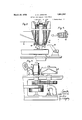
- Fig. 1 shows a store spooling device with one core inserted before a reel or swift
- FIG. 2 shows another spooling device on an enlarged scale
- Fig. 3 is a cross section of the main part
- Fig. 4 shows a. store spooling device according to Figure 1
- Fig. 5 shows a store spooling device with two cores.
- a shaft 1 drives the swift 2 and aspindle 3a of the yarn store 3, the circumferential velocity of the latter being greater than that of the first.
- a slotted drum 4 of known type serves for guiding the am in windings crossing each other in filling the store 3.
- the yarn comes from a spool or cop 5, positioned on the foot of the machine, and goes to the store3 and further through a yarn guiding device 6 to the swift 2.
- the store 3 may be fed with unrefined raw yarn or with yarn coming immediately from any other machine, as in it each bad piece or defect can immediately be removed.
- the yarn store is constructed as follows.
- a frame 7 rotatable with the spindle 3a supports four rollers 8 on its top and also on its lower end. All said rollers or at least those of the lower end are operatively connected to each other by conical gear wheels 9.
- An endless belt 10, for instance of rubber, is stretched out.
- a filling piece 11 is arranged for securing the belt against being pressed inward by the yarn to be wound on it.
- One of the axles of the lower rollers is provided with a driving cross 12 which on each revolution of the spindle 3a runs against a fixed abutment 13, so as to be somewhat rotated and drive the rollers and belts for axially displacing the stored yarn and make it easily detractable over the free head of the store.
- the abutment 13 is adjustable from hand at will or automatically by the machine, so as to come into or out of engagement on said driving cross 12.
- the yarn storing device shown in Fig. 1 has the following details.
- a spool sleeve 14 is mounted, and on the latter an annular cone 17 is slidable, for serving as a piece shaping the beginning of a spool body during winding its first layers.
- a conical and obliquely disposed guiding and pressing roller 15 serves for applying the yarn, which by a slotted drum 16 is led to thestore in a usual zig-zag or crosswise manner.
- the annular cone 17 travels to the spool top and is then removed, so that the yarn is free to be drawn off over the spool head during the further s oring work.
- a conical sleeve foot 14a imparts to the yarn spool the tendency of travelling up ward, and holds it suificiently loose for followin this tendency.
- the yarn body can ascend essentially over the sleeve top, but also if it has not reached such a position the yarn can easily be drawn off, so that a great quanof yarn is available for more or less quickly feeding the machine to be attended.
- the yarn to be stored is wound on two cores formed as drums 18, 19, the axles of which cross each other in different planes.
- One or both said axles are driven with the desired velocity both in the same direction of rotation.
- the first filling of the drums can be effected in any desired and usual manner, for instance, as described in my copending application Serial 37,817, by a belt to which the begin of the yarn is attached, and which in consequence of the crossing axles automatically travels alon the drums, for being thereafter remove
- the yarn travels in the same manner along the drums and is drawn oil over their free ends as demanded.
- the driving belt is adapted to be shifted to different diameters of a conical pulley and to an idle running pulley.
- a device for forming a yarn store comprising in combination a core held in bearings on one end, means for rotating said core, means for leading a yarn to the end of said core near said bearings, means for axially displacing said yarn wound on said core from said one end to the other end, and means for drawing off the yarn axially on said other end.
- a device for forming a yarn store comprising in combination a core held'in bearings on one end, means for rotating said core, means for leading a yarn to the end of said core near said bearings, a conical part adjacent the bearing end of said core, diminishing in diameter from the bearing end against the free end, for axially displacing said yarn wound on said core from said one end to the other end, and means for drawing off the yarn axially on said other end.
- a device for forming a yarn store comprising in combination a core held in bearings on one end. means for rotating said core, a traversing feed for leading the yarn to said core near said bearings, means for axially displacing said yarn wound on said core from said one end to the other end, and means for drawing off the yarn axially on said other end.
- a device for forming a yarn store comprising in combination a core held in bearings on one end, means comprising a speed changing gear adapted to rotate said core 1 with at least two different speeds, means for leading a yarn to the end of said core near said bearings, means for axially displacing said yarn wound on said core from said one end to the other end, and means for draw- 1 ing off the yarn axially on said other end, said drawing off speed being smaller than the greater speed generated by said speed changm gear.
Landscapes
- Winding Filamentary Materials (AREA)
Description
March 29, 1932. A, JUNKERS 1,851,252
DEVICE FOR FIORMING YARN STORES Filed Sept. 19, 1929 2 Sheets-Sheet 1 March 29, 1932. JUNKERS 1,851,252
DEVICE FOR FORMING YARN STORES Filed Sept. 19, 1929 2 Sheets-Sheet 2 Patented Mar. 29, 1932 UNITED STATES PATENT OFFICE ADOLF HEINRICH JUNKEBS, OF RHEYDT, GERMANY DEVICE FOR FORMING YARN STORES Application filed September 19, 1929, Serial No. 898,737, andin Germany February 28, 1925.
the yarn of which can be detracted over the I spool head, and by attaching again and again new spools, an uninterrupted yarn can be delivered. In the manufacture of banks it is further known to wind the yarn up on yarn cores provided with belts running over rollers for axially displacing the yarn while being wound up, and delivering completed hanks. Finally it is known for feeding slowly running, doubling and twisting machines, to fill an outer receiver casing with yarn windings on one end and feed the machine from the other end.
The invention has the object of feeding any devices for treating or consuming yarn uninterruptedly with an easily detractable yarn of any desired-length, so as to avoid any stopping, and give the possibility to remove bad yarnpieces or settle defects. This is accomplished by storing a considerable yarn quantity in a spool like body, in which the entering yarn is continuously wound on one or several cores, the whole body is continuously axially displaced on said core or cores, and on the free end of said core or cores the yarn is available for being drawn ofi' continuously or interruptedly at will. The yarn is thus able to be stored in regular windings with suflicient tension and high velocity on rigid cores, and it is also able to be delivered with high velocity to any consuming machine. At once the complete independency of the entering .and delivery movements of the yarn gives the possibility of settling any defects in the entering part, which for this purpose can be stopped. The new device can also be inserted into a yarn running from u one treating machine to any other, for forming a yarn store enabling both machines to cooperate with each other fully automatically, even with inconstant working velocities.
On the placing the yarn, or two or more cores can be used in the shape of drums with axes having no common plane but crossing each other in different planes so as to automatically transport the yarn in axial direction while it runs round them. In all cases one end of each yarn core must be free for delivering the yarn over said ends.
A valuable detail of the invention consists in providing the winding drive with at leasttwo velocities, one of which corresponds to provided with running belts for axially disthat of the machine to be fed, the other being higher for giving the possibility of augmenting the yarn quantity on the store after it has been diminished in consequence of a sto page needed for removing any irregularity in the passing yarn. Several embodiment of the invention are shown in the drawings, in which Fig. 1 shows a store spooling device with one core inserted before a reel or swift,
.Fig. 2 shows another spooling device on an enlarged scale,
Fig. 3 is a cross section of the main part,
Fig. 4 shows a. store spooling device according to Figure 1,
Fig. 5 shows a store spooling device with two cores.
In Fig. 1 a shaft 1 drives the swift 2 and aspindle 3a of the yarn store 3, the circumferential velocity of the latter being greater than that of the first. A slotted drum 4 of known type serves for guiding the am in windings crossing each other in filling the store 3. The yarn comes from a spool or cop 5, positioned on the foot of the machine, and goes to the store3 and further through a yarn guiding device 6 to the swift 2. As the swift runs with smaller circumferential velocity than the store 3, on the latter in some time a quantity of yarn is stored, which allows of tioned purposes, without stopping the swift tity 2, so that the latter is able to uninterruptedly do its Work until "the desired thickness of the hank is reached. The store 3 may be fed with unrefined raw yarn or with yarn coming immediately from any other machine, as in it each bad piece or defect can immediately be removed.
According to Figs. 2 and 3 the yarn store is constructed as follows. A frame 7 rotatable with the spindle 3a supports four rollers 8 on its top and also on its lower end. All said rollers or at least those of the lower end are operatively connected to each other by conical gear wheels 9. Over each pair of corresponding upper and lower rollers 8 an endless belt 10, for instance of rubber, is stretched out. Between each pair of rollers and the parts of the belt running over it, a filling piece 11 is arranged for securing the belt against being pressed inward by the yarn to be wound on it. One of the axles of the lower rollers is provided with a driving cross 12 which on each revolution of the spindle 3a runs against a fixed abutment 13, so as to be somewhat rotated and drive the rollers and belts for axially displacing the stored yarn and make it easily detractable over the free head of the store. The abutment 13 is adjustable from hand at will or automatically by the machine, so as to come into or out of engagement on said driving cross 12.
According to Fig. 4 the yarn storing device shown in Fig. 1 has the following details. On the driving spindle 3a a spool sleeve 14 is mounted, and on the latter an annular cone 17 is slidable, for serving as a piece shaping the beginning of a spool body during winding its first layers. A conical and obliquely disposed guiding and pressing roller 15 serves for applying the yarn, which by a slotted drum 16 is led to thestore in a usual zig-zag or crosswise manner. During and after the so performed formation of the spool, the annular cone 17 travels to the spool top and is then removed, so that the yarn is free to be drawn off over the spool head during the further s oring work.
A conical sleeve foot 14a imparts to the yarn spool the tendency of travelling up ward, and holds it suificiently loose for followin this tendency. The yarn body can ascend essentially over the sleeve top, but also if it has not reached such a position the yarn can easily be drawn off, so that a great quanof yarn is available for more or less quickly feeding the machine to be attended.
According to Fig. 5 the yarn to be stored is wound on two cores formed as drums 18, 19, the axles of which cross each other in different planes. One or both said axles are driven with the desired velocity both in the same direction of rotation. The first filling of the drums can be effected in any desired and usual manner, for instance, as described in my copending application Serial 37,817, by a belt to which the begin of the yarn is attached, and which in consequence of the crossing axles automatically travels alon the drums, for being thereafter remove The yarn travels in the same manner along the drums and is drawn oil over their free ends as demanded.
For changing the speed of the yarn store, according to Fig. 1 the driving belt is adapted to be shifted to different diameters of a conical pulley and to an idle running pulley.
I claim:
1. A device for forming a yarn store, comprising in combination a core held in bearings on one end, means for rotating said core, means for leading a yarn to the end of said core near said bearings, means for axially displacing said yarn wound on said core from said one end to the other end, and means for drawing off the yarn axially on said other end.
2. A device for forming a yarn store, comprising in combination a core held'in bearings on one end, means for rotating said core, means for leading a yarn to the end of said core near said bearings, a conical part adjacent the bearing end of said core, diminishing in diameter from the bearing end against the free end, for axially displacing said yarn wound on said core from said one end to the other end, and means for drawing off the yarn axially on said other end.
3. A device for forming a yarn store, comprising in combination a core held in bearings on one end. means for rotating said core, a traversing feed for leading the yarn to said core near said bearings, means for axially displacing said yarn wound on said core from said one end to the other end, and means for drawing off the yarn axially on said other end.
A device for forming a yarn store, comprising in combination a core held in bearings on one end, means comprising a speed changing gear adapted to rotate said core 1 with at least two different speeds, means for leading a yarn to the end of said core near said bearings, means for axially displacing said yarn wound on said core from said one end to the other end, and means for draw- 1 ing off the yarn axially on said other end, said drawing off speed being smaller than the greater speed generated by said speed changm gear.
Tn witness whereof I afl-ix my signature. ADOLF HEINRICH JUNKERS.
Priority Applications (1)
| Application Number | Priority Date | Filing Date | Title |
|---|---|---|---|
| US526484A US1849983A (en) | 1929-09-19 | 1931-03-30 | Device for forming alpha yarn store |
Applications Claiming Priority (1)
| Application Number | Priority Date | Filing Date | Title |
|---|---|---|---|
| DE1851252X | 1925-02-28 |
Publications (1)
| Publication Number | Publication Date |
|---|---|
| US1851252A true US1851252A (en) | 1932-03-29 |
Family
ID=7746024
Family Applications (1)
| Application Number | Title | Priority Date | Filing Date |
|---|---|---|---|
| US393737A Expired - Lifetime US1851252A (en) | 1925-02-28 | 1929-09-19 | Device for forming yarn stores |
Country Status (1)
| Country | Link |
|---|---|
| US (1) | US1851252A (en) |
Cited By (4)
| Publication number | Priority date | Publication date | Assignee | Title |
|---|---|---|---|---|
| US3225446A (en) * | 1961-10-31 | 1965-12-28 | Sobrevin Soc De Brevets Ind Et | Method and apparatus for handling filaments |
| US4026484A (en) * | 1971-06-19 | 1977-05-31 | Pavena Ag | Apparatus for controlling a winding device for a continuously supplied fiber sliver |
| US4042989A (en) * | 1975-04-08 | 1977-08-23 | Robreli Holding S.A. | Method for packaging and dyeing yarns and yarn packaging obtained thereby |
| US4669676A (en) * | 1985-03-29 | 1987-06-02 | Neumunstersche Maschinen-und Apparatebau GmbH (Neumag) | Device for depositing cables |
-
1929
- 1929-09-19 US US393737A patent/US1851252A/en not_active Expired - Lifetime
Cited By (4)
| Publication number | Priority date | Publication date | Assignee | Title |
|---|---|---|---|---|
| US3225446A (en) * | 1961-10-31 | 1965-12-28 | Sobrevin Soc De Brevets Ind Et | Method and apparatus for handling filaments |
| US4026484A (en) * | 1971-06-19 | 1977-05-31 | Pavena Ag | Apparatus for controlling a winding device for a continuously supplied fiber sliver |
| US4042989A (en) * | 1975-04-08 | 1977-08-23 | Robreli Holding S.A. | Method for packaging and dyeing yarns and yarn packaging obtained thereby |
| US4669676A (en) * | 1985-03-29 | 1987-06-02 | Neumunstersche Maschinen-und Apparatebau GmbH (Neumag) | Device for depositing cables |
Similar Documents
| Publication | Publication Date | Title |
|---|---|---|
| US2737773A (en) | Apparatus for making elastic yarn | |
| US723178A (en) | Cord or rope making machine. | |
| US1851252A (en) | Device for forming yarn stores | |
| US1460949A (en) | Paper-reenforcing machine and method thereof | |
| US2342343A (en) | Apparatus for making flexible shafting | |
| US2464536A (en) | Cord processing apparatus | |
| US2131893A (en) | Process and apparatus for twisting threads | |
| US2048787A (en) | Yarn packaging device | |
| US1972290A (en) | Stranding | |
| US1849983A (en) | Device for forming alpha yarn store | |
| US2143876A (en) | Drafting apparatus | |
| US2326307A (en) | Yarn winding mechanism | |
| US2454405A (en) | Yarn feed for twisting machines | |
| US1822415A (en) | Thread winding machine | |
| US2224110A (en) | Strand covering apparatus | |
| US1031367A (en) | Cord or rope making machine. | |
| US1906543A (en) | Stranding | |
| US2463689A (en) | Apparatus and method for making curled yarn | |
| US2448743A (en) | Cord processing apparatus | |
| US2255108A (en) | Machine and method for making flexible shafting | |
| US1922146A (en) | Thread feeding mechanism | |
| US2199550A (en) | Process and apparatus for handling elastic filaments | |
| US2110926A (en) | Process for making yarn packages | |
| US2181267A (en) | Reciprocating guide head for yarn packaging device | |
| GB542313A (en) | Improvements in method of making elastic yarn |