US1851231A - Handle structure - Google Patents
Handle structure Download PDFInfo
- Publication number
- US1851231A US1851231A US333657A US33365729A US1851231A US 1851231 A US1851231 A US 1851231A US 333657 A US333657 A US 333657A US 33365729 A US33365729 A US 33365729A US 1851231 A US1851231 A US 1851231A
- Authority
- US
- United States
- Prior art keywords
- cap
- grip
- rod
- handle
- handle structure
- Prior art date
- Legal status (The legal status is an assumption and is not a legal conclusion. Google has not performed a legal analysis and makes no representation as to the accuracy of the status listed.)
- Expired - Lifetime
Links
- 238000010276 construction Methods 0.000 description 3
- 235000006629 Prosopis spicigera Nutrition 0.000 description 1
- 240000000037 Prosopis spicigera Species 0.000 description 1
Images
Classifications
-
- A—HUMAN NECESSITIES
- A47—FURNITURE; DOMESTIC ARTICLES OR APPLIANCES; COFFEE MILLS; SPICE MILLS; SUCTION CLEANERS IN GENERAL
- A47J—KITCHEN EQUIPMENT; COFFEE MILLS; SPICE MILLS; APPARATUS FOR MAKING BEVERAGES
- A47J45/00—Devices for fastening or gripping kitchen utensils or crockery
- A47J45/06—Handles for hollow-ware articles
- A47J45/061—Saucepan, frying-pan handles
Definitions
- This invention aims to provide a novel handle structure for ClOIl'lGSlJlC cooklng uten sils,and this applicationis basedon matter divided 'out of my prior application No; v g
- Figure 3 is a sectional view disclosing a part of the handle
- An inverted cup shaped lid 3' is seated in i the ring 2.
- the base 1 is provided with an outstanding lug 4, which detachably receives a stud 5 carried by'the ring 2.
- Thebasel has an outstanding tapered boss 8 which is oircularin cross section.
- the numeral 9 designates a cap having an end wall '11, the cap beingprovided with a recess 17 I which is shaped to conform to the boss 8, V the cap receiving the boss.
- Thebase 1 has handle H.
- Thenumeral 10 designates a rod, forming a memb'er of the handlevH,'the member 10 beingthreaded into theendwall 17 of the cap? 9. 1 At itslouter end, the rod 1 1 l0rha s aprojection "12 in the form of an-eye. 5i0n the rod lO is mounted-a grip 1410f any Figures 4 and 5 are sectional views showing desired shape and construction. In the present embodiment of the invention the grip is of spiral form. qThe grip 14 isengaged at f oneend by the eyeror projection 12, and is.
- the lid 3 is supplied with j a handle H which is constructed and mounted like the handle Hon base 1.
- a handle H which is constructed and mounted like the handle Hon base 1.
- 'Kbail 16 is pivota-lly mounted at its ends in the lugs 15 and V 6 andconstitutes'a means whereby the-ring 2 may be handledconveniently.
- axial bore thehandle being imadeup of a rod having a threaded inner end,jand an enlargement at its outer end, a removable grip onqthe rod, the enlargement being of greater diameter than the outer end of'the grip, the grip being abutted at its outer end 1 against the enlargement, and a hollow, cupshaped cap provided with anend wall threaded on the inner endof the rod, the cap being adjustable along thelthreaded end of therod,
Landscapes
- Engineering & Computer Science (AREA)
- Food Science & Technology (AREA)
- Walking Sticks, Umbrellas, And Fans (AREA)
Description
Filed Jan. 19. 1929 Patented Mar. '29, 1932 UNITED? STATES ram) wrALLEmor KINGSTON, TENNESSEE, assreivon To J'.E.,'1ATE, OFIMIDDLETOIQ' GEORGIA {HANDLE STRUCTURE" Applicationifiled January'IS, 1929. Seria1"No.3 33,6 57.'
This invention aims to provide a novel handle structure for ClOIl'lGSlJlC cooklng uten sils,and this applicationis basedon matter divided 'out of my prior application No; v g
' engaged at its opposite end by the wall 11 252,514, filed on February 7 [1928; 1
It is within the province'of the disclosure to improve generally and to enhance the utility of devices of that typeto which the presentinvention appertains. -With the above and other objects in view, the invention consists'in thenovel construction andarrangement of parts hereinafter described and claimed, 1t be ng understood may suggest without departing that, within the scope of; what is claimed, a E-m'echanic may make such changes as his skill from the spirit of the invention. 1 p
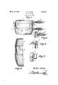
:In the accompanying drawings Figure l shows inside elevation, a device constructedin accordance with the invention; Figure 2 is a fragmental transverse sectlon of the article shown in Figure 1; Y
Figure 3 is a sectional view disclosing a part of the handle;
An inverted cup shaped lid 3' is seated in i the ring 2. The base 1 is provided with an outstanding lug 4, which detachably receives a stud 5 carried by'the ring 2.
I There is a lug 6 on the ring 2, and this lug detachablyreceives a stud? on the lid 3.
Thebasel has an outstanding tapered boss 8 which is oircularin cross section. The numeral 9 designates a cap having an end wall '11, the cap beingprovided with a recess 17 I which is shaped to conform to the boss 8, V the cap receiving the boss. Thebase 1 has handle H. Thenumeral 10 designates a rod, forming a memb'er of the handlevH,'the member 10 beingthreaded into theendwall 17 of the cap? 9. 1 At itslouter end, the rod 1 1 l0rha s aprojection "12 in the form of an-eye. 5i0n the rod lO is mounted-a grip 1410f any Figures 4 and 5 are sectional views showing desired shape and construction. In the present embodiment of the invention the grip is of spiral form. qThe grip 14 isengaged at f oneend by the eyeror projection 12, and is.
of the cap 9.. The general construction'is such that an unusually strong handle mount-v ing is provided.) The lid 3 is supplied with j a handle H which is constructed and mounted like the handle Hon base 1. There is a "lug 15 on the ringQ, the lu 15 being disposed opposite to the lug 6. 'Kbail 16 is pivota-lly mounted at its ends in the lugs 15 and V 6 andconstitutes'a means whereby the-ring 2 may be handledconveniently.
What is claimedis axial bore, thehandle being imadeup of a rod having a threaded inner end,jand an enlargement at its outer end, a removable grip onqthe rod, the enlargement being of greater diameter than the outer end of'the grip, the grip being abutted at its outer end 1 against the enlargement, and a hollow, cupshaped cap provided with anend wall threaded on the inner endof the rod, the cap being adjustable along thelthreaded end of therod,
tovcause the end wall to engage theinner end of the grip and bind the outer end'of the grip against the enlargement, the capbeing f open, after the cap hasbeen threaded against the grip, thereby to leavethe cap infcondition, 7 i
to receive the "boss, and the threaded inner end: of the rod projecting into the cap, for reception in the axial bore of the boss.
f In testimony thatl claimthe foregoing as my own,Ihave hereto afiEiXed my sig'nature.
11 0f the cap 9, and being threaded'into the boss 8 tobind theboss tightly in the recess "FREDW. A LEN.
Priority Applications (1)
| Application Number | Priority Date | Filing Date | Title |
|---|---|---|---|
| US333657A US1851231A (en) | 1929-01-19 | 1929-01-19 | Handle structure |
Applications Claiming Priority (1)
| Application Number | Priority Date | Filing Date | Title |
|---|---|---|---|
| US333657A US1851231A (en) | 1929-01-19 | 1929-01-19 | Handle structure |
Publications (1)
| Publication Number | Publication Date |
|---|---|
| US1851231A true US1851231A (en) | 1932-03-29 |
Family
ID=23303716
Family Applications (1)
| Application Number | Title | Priority Date | Filing Date |
|---|---|---|---|
| US333657A Expired - Lifetime US1851231A (en) | 1929-01-19 | 1929-01-19 | Handle structure |
Country Status (1)
| Country | Link |
|---|---|
| US (1) | US1851231A (en) |
-
1929
- 1929-01-19 US US333657A patent/US1851231A/en not_active Expired - Lifetime
Similar Documents
| Publication | Publication Date | Title |
|---|---|---|
| US1577612A (en) | Fishing-pole support | |
| US3976282A (en) | Plant root extraction tool | |
| US2474498A (en) | Fishing float | |
| US1851231A (en) | Handle structure | |
| US2370840A (en) | Blind rivet hand tool | |
| US2151182A (en) | Handle for furniture and the like | |
| US2280486A (en) | Modeling instrument | |
| US2509013A (en) | Paintbrush having detachable brush sections | |
| US2606054A (en) | Lifter for cylinder heads | |
| US3800370A (en) | Conduit grip | |
| US2518006A (en) | Divided circular handle having interlocking means | |
| US2174588A (en) | Cushioned crutch | |
| US1517540A (en) | File holder | |
| US2297577A (en) | Counterbalance attachment for fishing rods | |
| US786755A (en) | Attachment for canes or umbrellas. | |
| US1710198A (en) | Speed wrench | |
| US1753566A (en) | Box hook | |
| US1400600A (en) | Adjustable hand-grip for crutches | |
| US2206019A (en) | Handle for fish poles | |
| US2433197A (en) | Handle for fishing rods | |
| US2594392A (en) | Mop holder having a hollow handle and a retractable jaw | |
| US2076813A (en) | Jar holder | |
| US1662316A (en) | Handle | |
| US2454989A (en) | Auxiliary tool handle | |
| US2183906A (en) | Pipe cleaner |