US1851183A - Oven - Google Patents
Oven Download PDFInfo
- Publication number
- US1851183A US1851183A US175043A US17504327A US1851183A US 1851183 A US1851183 A US 1851183A US 175043 A US175043 A US 175043A US 17504327 A US17504327 A US 17504327A US 1851183 A US1851183 A US 1851183A
- Authority
- US
- United States
- Prior art keywords
- oven
- shelf
- movable
- class described
- moving
- Prior art date
- Legal status (The legal status is an assumption and is not a legal conclusion. Google has not performed a legal analysis and makes no representation as to the accuracy of the status listed.)
- Expired - Lifetime
Links
- 239000000969 carrier Substances 0.000 description 10
- 230000003028 elevating effect Effects 0.000 description 5
- 101100149158 Escherichia coli (strain K12) secM gene Proteins 0.000 description 1
- 239000010425 asbestos Substances 0.000 description 1
- 238000005266 casting Methods 0.000 description 1
- 238000010411 cooking Methods 0.000 description 1
- 230000000994 depressogenic effect Effects 0.000 description 1
- 238000009432 framing Methods 0.000 description 1
- 230000004048 modification Effects 0.000 description 1
- 238000012986 modification Methods 0.000 description 1
- 108010085990 projectin Proteins 0.000 description 1
- 230000000284 resting effect Effects 0.000 description 1
- 229910052895 riebeckite Inorganic materials 0.000 description 1
- 238000007789 sealing Methods 0.000 description 1
- 101150037744 srrA gene Proteins 0.000 description 1
Images

Classifications
-
- F—MECHANICAL ENGINEERING; LIGHTING; HEATING; WEAPONS; BLASTING
- F24—HEATING; RANGES; VENTILATING
- F24C—DOMESTIC STOVES OR RANGES ; DETAILS OF DOMESTIC STOVES OR RANGES, OF GENERAL APPLICATION
- F24C15/00—Details
- F24C15/16—Shelves, racks or trays inside ovens; Supports therefor
- F24C15/168—Shelves, racks or trays inside ovens; Supports therefor with telescopic rail systems
-
- A—HUMAN NECESSITIES
- A21—BAKING; EDIBLE DOUGHS
- A21B—BAKERS' OVENS; MACHINES OR EQUIPMENT FOR BAKING
- A21B1/00—Bakers' ovens
- A21B1/50—Bakers' ovens characterised by having removable baking surfaces
Definitions
- HILL or MANHATTAN BEACH,TNEW YORK,.ASSIGNOR 'ro GRIFFITHA 7E. HILL, on NEW YORK, lm'Y. r
- My invention relates to improvements in cooking ranges, 'or'stoves, and more particuin and out of the oven.
- larly has reference to an oven having an adjustable shelf or bottom, or both, with means for operating thesame, so as to bring thefood or raise or lower the same as may be desired.
- FIG. 1 illustrates in perspective, parts being broken away, part of a gas range oven embodying an application .of my invention.
- Fig.2 is an enlarged detail in perspective of part of the slide mechanism thereof.
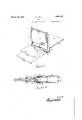
- Fig. 3 is a perspective view, parts omitted, illustrating an oven door and sliding bottom arrangement
- Fig. 4 is a longitudinal sectional view of the slide mechanism on the line 4 -4 of Fig. 1'
- Fig. 5 is a front view at one side of the oven, parts being broken away,.illustrating the slide mechanism.
- the shelf or tray 30, of the'oven is'preferably inthe form of a grid or grill, and is carried by the side slides 31, 31, which are slidably mounted within the channels 32, 32, which in turn slide within the'channels 13.
- the rear ends of eachof the slides 31, 31, are provided with rollers33,mounted upon brackets 34, shown to advantage in Fig. 2, said brackets having 1 depending lug 35, for attachment to the operating sprocket chain.
- rollers ' suchas 34, for abutting similar stops 35, in the channel32, for limiting the outward extension of'the slide 31, in the slide 32, and rollers 36 are also preferably provided within and at-the outer end of the slide 32, as shown.
- Similar rollers 3'? are also preferably provided inthe outer end of the-carrier 13, within which the channel 32 slides or rolls, and the said.
- carrier 13 is also prefer- I ably provided with stops 38, which likethe other stops maybe pressed out. of the flange y from the carrier 13.
- 40, 41 also indicate rollers, pivotally mounted in the turned out flanges 42, of the channel 32, and 43, 44, indicate turned in flanges at the inner end of the carrier 13, serving as a stop for the inward projection of the channels.
- the smaller slide member 31 is first pushed leftwardly through the channel 32, after which, and before the flanges 43, 44, are bent in, the channel 32 is slid from right to left into the carrier 13.
- the tray 30 being secured along the inner sides of the slides 31. 31', it will be observed may now be rolled entirely into or substantially entirely out of the oven, being well braced or supported in either position.
- the entire weight is carried in the carriers 13, supported by the carrier plates 9, and in turn supported by the vertical slide casting 10, 10, through the connecting pins and rollers 11, 1.2. so that when the handle 29 is rotated, the entire shelf or tray of the oven may be raised or lowered the entire vertical length of the oven.
- An endless sprocket chain is connected to the lugs 35 at each side of and beneath the tray 30, said chain extending forwardly from the lug 35 around the sprocket wheel 46, pivotally mounted on the Z-plate 47, secured to the carriers 9, beneath the slide carriers 13.
- This chain continues laterally around the outside of the sprockets 19, and inwardly again around the inner sides of the sprockets 22, continuing rearwardly around sprocket- 48, pivotally mounted on the carrier 10, and then around the sprocket 49, also mounted upon the Z-bracket 47, as shown, and forwardly again to the bracket 35, so that when the splined shafts 15 are rotated by the handle 28, the tray or shelf is projected substantially entirely out of the oven, and may be returned within the same by reversed movement of said handle.
- Similar slide projecting mechanism may be employed for the bottom of the oven, except that instead of using the splined shafts and sprocket mechanism, the same may, if desired, be withdrawn by hand, the handle of the bottom being always outside of the oven and insulated therefrom so as to remain cool.
- Fig. 3 where it will be seen that the door is provided with the usual handle 51, and hinges 52, secured to the side frames 53,'the top frame of the door opening being broken away for'convenience. 54
- the door panel 50, and lining 59 are cut away rectangularly as shown at 60, for the passage of the handle 61, which is attached to the front of the oven bottom, said lining 59 engaging the frame around the handle 61, preventing the ingress or egress of any air from into or out of the oven when the door is closed, the handle 61 being preferably curved at the top on a radius drawn from the center of the hinge 52, so as to provide a sliding fit between the top of the handle and the door.
- the bottom may be drawn outwardly as indicated in dotted outline at 54, thus presenting the contents of the oven bottom for manipulation or treatment, after which the same may be returned, and the oven door closed, thoroughly sealing the front of the oven, but leaving the handle (31 exposed in the room, where it is kept cool, and any suitable arrangement may be provided for insulating said handle from the oven bottom, such as asbestos backing, etc.
- the hood-like portion 61 of the handle being curved, presents the conventional hollow under portion for engagementwith the lingers in the usual manner- From the foregoing it will be obvious that when the door of the oven is opened, the
- the elevating tray 30 when entirely depressed may be brought down so that the apron 62 rests upon the top of the bottom 55, so that when the shelf is entirely down and the oven is opened, it presents the appearance of a slightly elevated bottom, of grill form, until the elevating handle is operated, when the shelf may be carried upwardly behind the top cross frame of the door entrance, leaving the entire interior area available for use, and thus presenting an appearance so nearly identical with the ordinary oven as to leave only the outside handles for suggesting the use of any mechanism in connection therewith.
- the channel plates or side lining 6, 7 are of course slightly spaced, say not more than a quarter of an inch from the front and back of the oven to allow for the passage of the carriers 9, and chains 45 transversely therethrough, as indicated at the cut-away portion 63. These spaces are so small, however, as not to be observed, owing to the sides of the door frame and are too small to permit of interference in any manner.
- An oven thus constructed may be said to be completely clear of all operating mechanism which is substantially entirely concealed within the linings thereof, avoiding the loss of any of the cubic capacity of the oven, providing for maximum movements of the shelf in two directions, and of the oven bottom outwardly and inwardly, and of course it will be readily understood that suitable automatic operating mechanism may be pro- 13 vided, such as an electric motor, in place of the handles, should the, same be desired.
- said grid adapted tobe moved between said grid vertically and horizontally between said linings.
- An oven of the class described having ashelf, means for moving the same vertically or horizontally, substantially. all ofsaid means outside the useful portion of said ovenand within the walls'and shelf thereof.
- an adjustable supportwerein In combination with an oven of the class described, an adjustable supportwerein, and means for adjusting said support vertically and longitudinally without obstruct ing said oven above or below the same.
- an adjustable support therein, and means for adjusting said support vertically and longitudinally without obstructing said oven above or below the same, and in combination therewith, means for automatically securing said support in its vertically adjusted position.
- an oven having a movable shelf, a plurality of maintaining same in parallel horizontal pos1t1on wlth respect to one another, said shelf shelf supports, means for simultaneously 1 'raisingand lowering said supports while upon said supports, an operating member positioned exterior and removable from the heated area, and operative connections between said member and-said shelf for movingthe same longitudinally of said supports,
- Anoven shelf projecting mechanism in-' eluding slides at opposite sides of said shelf, a sprocket chain connected thereto, and means for driving said chain, and a hand control for. said means outside. of said oven.
- An oven shelf projecting mechanism including slides at opposite sides of said shelf, a sprocket clain connected thereto, and means for driving said chain, said means between the lining and Walls of said oven.
- the cl movable shelf, and roller be: i nal extension supports therefor, an sgroclzet chain driven mechanism projecting said shelf from outside sa d even including et wheels, s rews and co o ed. but separately or -..c class a movable shelf and a movable bottom, a1 means for imparting six differentmovements thereto.
- An oven of the class ...cribed having a movable bottom and. means for moving the same in and out of said oven, said 11.921115 outside of said oven and ie door thereof.
- An oven having a snelf and bottom therein, and a handle for said bottom extending outside said oven, il l proj ting through the door of said oven on y .vhen same is closed.
- An oven of the class de cribed having a movable bottom and means for moving the same in and out of said oven, a handle attached to said bottom but free of and extending outside the same.
- a chamber havimg' a movable bottom and mov able shelf therein, means for moving said shelf vertically and means for moving said shelf or bottom laterally.
- An oven of the class i a movable shelf and means for in'iparting thereto, controlling means the-..ior on said oven.
- An oven of the class described having a movable shelf and a movable bottom, and means for imparting six different movements thereto, without occupying the useful space of said oven.
- An oven of the class described having a movable bottom and means for moving the same in and out of said oven, and an outside controlled tray adapted to rest immediately above said bottom.
- An oven of the class described having a movable shelf and a movable bottom, controlling means therefor out-side said oven, said bottom movable independently of the movement of said shelf.
- An oven of the class described having a movable shelf and a movable bottom, controlling means therefor outside said oven, said shelf movable independently of the movement of said bottom.
- An oven of the class described having a movable shelf and a movable bottom, and means for imparting six different movements thereto, without substantially detracting from the capacity of said oven.
- An oven of the class described having a projectable shelf and means for elevating the same, and in combination therewith a projectable bottom adapted to be operated independently of said shelf.
- An oven of the class described having a movable shelf therein, and means for moving the same either vertically or transversely, a movable bottom in said oven, and means for operating the same without interference with said movable shelf.
- An oven of the class described having a movable bottom and means for moving the same in and out of said oven, a him-rd door for said oven, a handle for said bottom extending through said door, said handle curved about the axis of said door hinge.
- a chan'iber having a movable bottom and movable shelf therein, and means controlled from outside said chamber for moving said shelf vertically in two directions or for moving said bottom latera ly in two directions.
- An oven of the class described having a movable shelf and bottom therein, and means outside said ovenfor automatically adjusting either said shelf or said bottom, each of said means adapted to impart either of two opposed movements.
- An oven of the class described having amovable shelf and a movable bottom,'controlling means therefor outside said oven, said controlling means adapted to operate said shelf in four directions and said bottom in two directions.
- An oven of the class described having a shelf independently movable in directions at an angle one to the other, and means ou side said oven for controlling said move-' ments, and in combination therewith means for moving the bottom of said oven;
- a chamber having a movable bottom and movable shelf therein, means for moving said shelf vertically and means for moving said shelf or bottom laterally, said means controlled from outside said chamber.
- An oven of the class described having a movable shelf and a movable bottom, controlling means therefor outside said oven, said bottom behind and secured to a part of the front frame of said oven and projectable therewith.
- An oven of the class described having a movable bottom and means for moving the same in. and'out of said oven, said means adapted to pass through but unattached to the door of said oven when closed without allowing the passage of air: through the opening therefor.
- chamber having a movable bottom and movable shelf therein, means for moving sa1d shelf vertically and means for moving said shelf or bottom laterally, all of said means being substantially concealed beyond the useful zone of said chamber.
- An oven of the classdescribed having a shelf and means for movingthe same in two directions at an angleone to the other, said .means adapted to. operate independently of any similar mechanismlin any adjoining oven, and a movable bottom in said oven.
- a chamber having a movable bottomand movable shelf therein, means'for moving said shelf vertically and means for moving said shelf or bottom laterally, said shelf adapted to be raised against the top orlowered'upon 59.
- An oven of the class described having a shelf and means for moving the same in two 4 directions at an angle one to theother, said means adapted to operate independently of any similar mechanism in any adjoining oven, a movable bottom in said oven, and means outside said oven for operating the same.
- a chamber having a movable bottom and mov ableshelf therein, means controlled from outside said chamber forv moving said shelf vertically and means for moving said bottom laterally, said lateral movingmeans being inoperative until the door of said chamber has been opened.
- An oven of the class described having a movable shelf and bottom therein, and means outside said oven for automatically adj usting either said shelf or said bottom, said means comprising three independent instrumentalities, each of which are adapted to activate either of two opposed movements.
- a chamber having a movable bottom and movable shelf therein, means for moving said shelf vertically and means for moving said/ ments, and in combination therewith means.
- a chamber having a movable bottom and movable shelf therein means controlled from outside said. chamber for moving said shelf vertically substantially the entire height of 1 said chamber or for moving said shelf or said bottom laterally substantially the. entire depthof said chamber.
- a chamber having a movable bottom and movable shelf therein, means for moving. said shelf vertically and means for moving-said shelf or bottom laterally, saidmeans controlled from outside said chamber. said signature. 1 THOMAS A. HILL.
Landscapes
- Engineering & Computer Science (AREA)
- Life Sciences & Earth Sciences (AREA)
- Food Science & Technology (AREA)
- Chemical & Material Sciences (AREA)
- Combustion & Propulsion (AREA)
- Mechanical Engineering (AREA)
- General Engineering & Computer Science (AREA)
- Electric Ovens (AREA)
Description
T. A. HlLL March 29, 1932.
OVEN
Filed March 14. 1927 2 Sheets-Sheet l avwamto'c T. A. IHILL' March 29, 1931 OVEN Filed March 14. 1927 2 Sheets-Sheet amoe mt oz srrA,
is PATENT Fries.
' THOMAS A. HILL, or MANHATTAN BEACH,TNEW YORK,.ASSIGNOR 'ro GRIFFITHA 7E. HILL, on NEW YORK, lm'Y. r
oven
Application filed March 14, 1927,. Serial no. 175,043.
My invention relates to improvements in cooking ranges, 'or'stoves, and more particuin and out of the oven.
larly has reference to an oven having an adjustable shelf or bottom, or both, with means for operating thesame, so as to bring thefood or raise or lower the same as may be desired.
Referring to the accompanying drawings, Fig. 1 illustrates in perspective, parts being broken away, part of a gas range oven embodying an application .of my invention.
Fig.2 is an enlarged detail in perspective of part of the slide mechanism thereof. Fig. 3 is a perspective view, parts omitted, illustrating an oven door and sliding bottom arrangement, Fig. 4 is a longitudinal sectional view of the slide mechanism on the line 4 -4 of Fig. 1', and Fig. 5 is a front view at one side of the oven, parts being broken away,.illustrating the slide mechanism. f
5 indicates the outer shell or casing ofthe stove, within which is suitably secured side linings 6, 7 and top lining 8, said linings being in the form of stamped plates, spaced inwardly from the outer casing aboutean inch and a half as usual. At each side of the oven, projecting and elevating mechanism is operatively mounted with reference to said'linings,
' but as the mechanis'mat'each side is substantially the same, parts have been omitted from one side or, the other side to prevent undue confusion and detail;
At opposite sides of the side liningsG, 7, are mounted vertically sliding carriers 9, 10, connected together by pins 11, having tubes or rollers 12 thereon, to ride against the front and backedges of the side linings 6, 7. The
carriers 9 serve to carry the slide bearings 13,
whilst-he carriers 10 are preferably cast with the enlarged portion 10', through which the screw 14, and shaft 15, pass, the lower ends of said screw and shaft having bearing support on the flange 16, extending outwardly from the sidelinings 6,7, andtlie upper endsof said screw and shaft being rotatably' supported in the top lining 8and having beveled pinions Resting upon thecarrier 10 is a sprocket wheel 19, slidablyengaging the splinedshaft 15, ,by tongue or pin 20, adaptedto :travel in "and similarly connected at the opposite side,-
so that by turning the handle 28 at the outside of the oven, the splined shafts 15 are rotated simultaneously and equally, and by turning the handle 29 at the outside of the oven, the screws '14 are turned equally and 1 simultaneously. The carriers 10 are of course threaded to receive the screws 14,are lifted thereby, and lift the carriers 9 and slide carriers 13, orrdepress the same according to the direction in which the handle 29 is turned. I
Referring now more particularlyto Figs. V 2 and 4, it will be observed that the shelf or tray 30, of the'oven, is'preferably inthe form of a grid or grill, and is carried by the side slides 31, 31, which are slidably mounted within the channels 32, 32, which in turn slide within the'channels 13. The rear ends of eachof the slides 31, 31, are provided with rollers33,mounted upon brackets 34, shown to advantage in Fig. 2, said brackets having 1 depending lug 35, for attachment to the operating sprocket chain. Immediately in front of the roller 33, may be provided suitable stops 'suchas 34, for abutting similar stops 35, in the channel32, for limiting the outward extension of'the slide 31, in the slide 32, and rollers 36 are also preferably provided within and at-the outer end of the slide 32, as shown. Similar rollers 3'? are also preferably provided inthe outer end of the-carrier 13, within which the channel 32 slides or rolls, and the said. carrier 13 is also prefer- I ably provided with stops 38, which likethe other stops maybe pressed out. of the flange y from the carrier 13. 40, 41, also indicate rollers, pivotally mounted in the turned out flanges 42, of the channel 32, and 43, 44, indicate turned in flanges at the inner end of the carrier 13, serving as a stop for the inward projection of the channels.
In assembling the slide or roller mechanism, the smaller slide member 31 is first pushed leftwardly through the channel 32, after which, and before the flanges 43, 44, are bent in, the channel 32 is slid from right to left into the carrier 13. The tray 30 being secured along the inner sides of the slides 31. 31', it will be observed may now be rolled entirely into or substantially entirely out of the oven, being well braced or supported in either position. The entire weight is carried in the carriers 13, supported by the carrier plates 9, and in turn supported by the vertical slide casting 10, 10, through the connecting pins and rollers 11, 1.2. so that when the handle 29 is rotated, the entire shelf or tray of the oven may be raised or lowered the entire vertical length of the oven.
An endless sprocket chain is connected to the lugs 35 at each side of and beneath the tray 30, said chain extending forwardly from the lug 35 around the sprocket wheel 46, pivotally mounted on the Z-plate 47, secured to the carriers 9, beneath the slide carriers 13. This chain continues laterally around the outside of the sprockets 19, and inwardly again around the inner sides of the sprockets 22, continuing rearwardly around sprocket- 48, pivotally mounted on the carrier 10, and then around the sprocket 49, also mounted upon the Z-bracket 47, as shown, and forwardly again to the bracket 35, so that when the splined shafts 15 are rotated by the handle 28, the tray or shelf is projected substantially entirely out of the oven, and may be returned within the same by reversed movement of said handle.
Similar slide projecting mechanism may be employed for the bottom of the oven, except that instead of using the splined shafts and sprocket mechanism, the same may, if desired, be withdrawn by hand, the handle of the bottom being always outside of the oven and insulated therefrom so as to remain cool. Such an arrangement is shown to advantage in Fig. 3, where it will be seen that the door is provided with the usual handle 51, and hinges 52, secured to the side frames 53,'the top frame of the door opening being broken away for'convenience. 54
indicates the. usual-type of oven bottom with depending flanges 55. 'The lower part of the door frame 56 has an upper portion 57, separated therefrom by the transverse cut 58. 59 indicates the usual inner lining of the door, which lays flush against the entire four sides of the door framing. The door panel 50, and lining 59, are cut away rectangularly as shown at 60, for the passage of the handle 61, which is attached to the front of the oven bottom, said lining 59 engaging the frame around the handle 61, preventing the ingress or egress of any air from into or out of the oven when the door is closed, the handle 61 being preferably curved at the top on a radius drawn from the center of the hinge 52, so as to provide a sliding fit between the top of the handle and the door. From the foregoing, it will be obvious that when the door is opened out and down, as indicated in dotted outline at 51, the bottom may be drawn outwardly as indicated in dotted outline at 54, thus presenting the contents of the oven bottom for manipulation or treatment, after which the same may be returned, and the oven door closed, thoroughly sealing the front of the oven, but leaving the handle (31 exposed in the room, where it is kept cool, and any suitable arrangement may be provided for insulating said handle from the oven bottom, such as asbestos backing, etc. The hood-like portion 61 of the handle being curved, presents the conventional hollow under portion for engagementwith the lingers in the usual manner- From the foregoing it will be obvious that when the door of the oven is opened, the
bottom of the oven will be immediately with the bottom frame of the door- The elevating tray 30 when entirely depressed may be brought down so that the apron 62 rests upon the top of the bottom 55, so that when the shelf is entirely down and the oven is opened, it presents the appearance of a slightly elevated bottom, of grill form, until the elevating handle is operated, when the shelf may be carried upwardly behind the top cross frame of the door entrance, leaving the entire interior area available for use, and thus presenting an appearance so nearly identical with the ordinary oven as to leave only the outside handles for suggesting the use of any mechanism in connection therewith. The channel plates or side lining 6, 7 are of course slightly spaced, say not more than a quarter of an inch from the front and back of the oven to allow for the passage of the carriers 9, and chains 45 transversely therethrough, as indicated at the cut-away portion 63. These spaces are so small, however, as not to be observed, owing to the sides of the door frame and are too small to permit of interference in any manner. An oven thus constructed may be said to be completely clear of all operating mechanism which is substantially entirely concealed within the linings thereof, avoiding the loss of any of the cubic capacity of the oven, providing for maximum movements of the shelf in two directions, and of the oven bottom outwardly and inwardly, and of course it will be readily understood that suitable automatic operating mechanism may be pro- 13 vided, such as an electric motor, in place of the handles, should the, same be desired.
Of course it will be understood that various modifications maybe 'madein. the constructionand arrangement of parts without departingfrom the spirit of the invention as claimed.
1. In an oven grid movement having means for-moving the grid vertically and horizontally, linings Within said movement,
said grid adapted tobe moved between said grid vertically and horizontally between said linings.
4. In combination with an oven of the. class described-, an adjustable support therein, means for adjusting said support vertically and longitudinally Without obstructing said oven above or below the same.
5. In combination with anoven grid operating device and the oven of a cook-stove, side linings'in said device spaced apart a distance substantially equal to the width of the opening to said oven.
6. In combination with an oven grid movement and a cook-stove having an oven, means for operating said grid in two directions at right angles one to the other, said means clear of the useful area of said oven.
7. In combination with an. oven having an adjustable shelf andmeans for raising same, means for projecting said shelf from said oven, none of said means occupying space within the projectedarea of the openingto said oven.
"8. In combination with an oven having an adjustable shelf and means. for raising same, means for projecting said shelf from said oven, all of said means substantially clear of the inwardly projected area ofsaid oven.
9. An oven of the class described having ashelf, means for moving the same vertically or horizontally, substantially. all ofsaid means outside the useful portion of said ovenand within the walls'and shelf thereof.
10. Incombination withra stove of the class described, anoven and remoyable linings therein, a movement for-shiftingthe grid of said oven vertically and horizontally, said movement operative irrespective of said linings.
11. In combination with an oven of the class described, an adjustable supportwerein, and means for adjusting said support vertically and longitudinally without obstruct ing said oven above or below the same.
12. In. combination with an oven ofv the class described, amovable shelf, means for moving the same vertically and horizontally,
outside control for operating said means, said first mentioned means clear of the useful area of said oven. V,
' 13. In combination with an oven having an adjustable shelf and means for raisingsame, means for projecting said shelf from said oven, all of said means substantially clear of the opening to said oven, and opera tive by a single lever.
14. A chamber having a movable shelf,
mechanism for moving said shelf in two directions at right angles to each other, said mechanism outside the useful zone of said an adjustable shelf and means, for. raising. same, means for projecting said shelf from said oven, allof said means substantially I clear of the opening to said oven, and operative by a single lever.
16. In combination with any oven of the class described, an adjustable support therein, and means for adjusting said support vertically and longitudinally without obstructing said oven above or below the same, and in combination therewith, means for automatically securing said support in its vertically adjusted position.
-17. In adeviceof the class described, an oven having a movable shelf, a plurality of maintaining same in parallel horizontal pos1t1on wlth respect to one another, said shelf shelf supports, means for simultaneously 1 'raisingand lowering said supports while upon said supports, an operating member positioned exterior and removable from the heated area, and operative connections between said member and-said shelf for movingthe same longitudinally of said supports,
whereby said member remains cool and the. '1
including slides at opposite. sides of said shelf, a sprocket chain connected thereto, and means for driving said chain, said slides hav- 12G 20.In an oven of the class described,
. movable shelf,-and roller bearing sectional ing roller bearings.
extension supports therefor, and sprocket chain driven mechanism. for pro ecting said shelf from outside said oven.
21. Anoven shelf projecting mechanism in-' eluding slides at opposite sides of said shelf, a sprocket chain connected thereto, and means for driving said chain, and a hand control for. said means outside. of said oven.
22. An oven shelf projecting mechanism including slides at opposite sides of said shelf, a sprocket clain connected thereto, and means for driving said chain, said means between the lining and Walls of said oven.
23. In an oven of the described, a movable shelf, and roller bearing sectional extension supports therefor, and sprocket chain driven mcchani n for projectii'ig said shelf from out lde said even, including splined shafts for driving sprocket Wheels.
24. In an oven shelf elevating and projecting mechanism, a driven serocket chain for projectin and a. Worm for eleva '-g said shelf, said projecting and elevatin mechanism substantially conceal-ed, and independently operative from separate controls outside said oven.
25. In an oven the cl movable shelf, and roller be: i nal extension supports therefor, an sgroclzet chain driven mechanism projecting said shelf from outside sa d even including et wheels, s rews and co o ed. but separately or -..c class a movable shelf and a movable bottom, a1 means for imparting six differentmovements thereto.
2?. An oven of t criaed naving a movable shelf and *able bottom, controlling means therefor outside said oven.
28. An oven of the class ...cribed having a movable bottom and. means for moving the same in and out of said oven, said 11.921115 outside of said oven and ie door thereof.
29. An oven having a snelf and bottom therein, and a handle for said bottom extending outside said oven, il l proj ting through the door of said oven on y .vhen same is closed.
In an even grid mov nent of the class described, means for mov the grill vertically and horizonta ly, and a movable bottom adapted to be moved horizontally independently of said grid.
31. An oven of the class de cribed having a movable bottom and means for moving the same in and out of said oven, a handle attached to said bottom but free of and extending outside the same.
32. In a device of the class described, a chamber havimg' a movable bottom and mov able shelf therein, means for moving said shelf vertically and means for moving said shelf or bottom laterally.
33. An oven of the class (i a movable shelf and means for in'iparting thereto, controlling means the-..ior on said oven.
6 An oven of th:
outside said oven for automatically adjusting either said shelf or said bottom.
35. An oven of the class described having a movable shelf and a movable bottom, and means for imparting six different movements thereto, without occupying the useful space of said oven.
36. An oven of the class described having a movable bottom and means for moving the same in and out of said oven, and an outside controlled tray adapted to rest immediately above said bottom.
An oven of the class described having a movable shelf and a movable bottom, controlling means therefor out-side said oven, said bottom movable independently of the movement of said shelf.
38. An oven of the class described having a movable shelf and a movable bottom, controlling means therefor outside said oven, said shelf movable independently of the movement of said bottom.
39. An even of the class described having a movable shelf and a movable bottom, controlling means therefor outside said oven, said shelf movable in two planes at right angles to each other.
40. An oven of the class described having a movable shelf and a movable bottom, and means for imparting six different movements thereto, without substantially detracting from the capacity of said oven.
41. An oven of the class described having a projectable shelf and means for elevating the same, and in combination therewith a projectable bottom adapted to be operated independently of said shelf.
42. An oven of the class described having a movable bottom and means for moving the same in and out of said oven, said means adapted to project through but unattached to the door of said oven when the same is closed.
43. An even of the class described having a niovablc shelf and bottom therein, and means outside said oven for automatically adjusting either said shelf or said bottom in the same or different directions.
{44. An oven of the class described having a movable shelf therein, and means for moving the same either vertically or transversely, a movable bottom in said oven, and means for operating the same without interference with said movable shelf.
45. An oven of the class described having a movable bottom and means for moving the same in and out of said oven, a him-rd door for said oven, a handle for said bottom extending through said door, said handle curved about the axis of said door hinge.
-16. In a device of the class described, a chan'iber having a movable bottom and movable shelf therein, and means controlled from outside said chamber for moving said shelf vertically in two directions or for moving said bottom latera ly in two directions.
47. An oven of the class described having a movable shelf. and bottom therein, and
means outside said oven for automatically adjusting either said shelf or said bottom, so as "shelf or bottom laterally, said shelf being to bring either substantially out of or into said oven.
48. An oven of the class described having a movable shelf and bottom therein, and means outside said ovenfor automatically adjusting either said shelf or said bottom, each of said means adapted to impart either of two opposed movements. I
49. An oven of the class described having amovable shelf and a movable bottom,'controlling means therefor outside said oven, said controlling means adapted to operate said shelf in four directions and said bottom in two directions. p
50. An oven of the class described having a shelf independently movable in directions at an angle one to the other, and means ou side said oven for controlling said move-' ments, and in combination therewith means for moving the bottom of said oven;
51. In a device of the class described, a chamber having a movable bottom and movable shelf therein, means for moving said shelf vertically and means for moving said shelf or bottom laterally, said means controlled from outside said chamber.
52. An oven of the class described having a movable shelf and a movable bottom, controlling means therefor outside said oven, said bottom behind and secured to a part of the front frame of said oven and projectable therewith.
53. An oven of the class described having a movable bottom and means for moving the same in. and'out of said oven, said means adapted to pass through but unattached to the door of said oven when closed without allowing the passage of air: through the opening therefor.
54. In a device of the class described, a*
chamber having a movable bottom and movable shelf therein, means for moving sa1d shelf vertically and means for moving said shelf or bottom laterally, all of said means being substantially concealed beyond the useful zone of said chamber.
55. In a device of the class described, a'
chamber havinga movable bottom and movable shelf therein, means for moving sa1d adapted to be moved laterally at anypoint of elevation of'the same.
56. An oven of the classdescribed having a shelf and means for movingthe same in two directions at an angleone to the other, said .means adapted to. operate independently of any similar mechanismlin any adjoining oven, and a movable bottom in said oven.
57 In a device of the class described, a chamber having a movable bottomand movable shelf therein, means'for moving said shelf vertically and means for moving said shelf or bottom laterally, said shelf adapted to be raised against the top orlowered'upon 59. An oven of the class described having a shelf and means for moving the same in two 4 directions at an angle one to theother, said means adapted to operate independently of any similar mechanism in any adjoining oven, a movable bottom in said oven, and means outside said oven for operating the same.
60. In a device of the class described, a chamber having a movable bottom and mov ableshelf therein, means controlled from outside said chamber forv moving said shelf vertically and means for moving said bottom laterally, said lateral movingmeans being inoperative until the door of said chamber has been opened.
61. An oven of the class described having a movable shelf and bottom therein, and means outside said oven for automatically adj usting either said shelf or said bottom, said means comprising three independent instrumentalities, each of which are adapted to inaugurate either of two opposed movements.
62. In a device of the class described, a chamberhaving a movable bottom and movable shelf therein, means for moving said shelf vertically and means for moving said/ ments, and in combination therewith means.
for moving the bottom of said oven, and
means outside said oven for controlling said last mentioned means.
64. Ina device of the class described, a chamber having a movable bottom and movable shelf therein, means controlled from outside said. chamber for moving said shelf vertically substantially the entire height of 1 said chamber or for moving said shelf or said bottom laterally substantially the. entire depthof said chamber.
65.'In a device of the class described, a chamber having a movable bottom and movable shelf therein, means for moving. said shelf vertically and means for moving-said shelf or bottom laterally, saidmeans controlled from outside said chamber. said signature. 1 THOMAS A. HILL.
Priority Applications (1)
| Application Number | Priority Date | Filing Date | Title |
|---|---|---|---|
| US175043A US1851183A (en) | 1927-03-14 | 1927-03-14 | Oven |
Applications Claiming Priority (1)
| Application Number | Priority Date | Filing Date | Title |
|---|---|---|---|
| US175043A US1851183A (en) | 1927-03-14 | 1927-03-14 | Oven |
Publications (1)
| Publication Number | Publication Date |
|---|---|
| US1851183A true US1851183A (en) | 1932-03-29 |
Family
ID=22638603
Family Applications (1)
| Application Number | Title | Priority Date | Filing Date |
|---|---|---|---|
| US175043A Expired - Lifetime US1851183A (en) | 1927-03-14 | 1927-03-14 | Oven |
Country Status (1)
| Country | Link |
|---|---|
| US (1) | US1851183A (en) |
Cited By (15)
| Publication number | Priority date | Publication date | Assignee | Title |
|---|---|---|---|---|
| US2919691A (en) * | 1955-08-22 | 1960-01-05 | Moffats Ltd | Mechanism for adjusting the height of racks in range ovens |
| US2979054A (en) * | 1957-05-17 | 1961-04-11 | Elmer T Jenkins | Door controlled sliding racks |
| US2987363A (en) * | 1957-12-13 | 1961-06-06 | Charles L Morse | Cooking oven |
| US3033636A (en) * | 1960-12-19 | 1962-05-08 | Gen Motors Corp | Refrigerator shelving |
| US3059634A (en) * | 1960-01-20 | 1962-10-23 | Susan B Brinkman | Power operated oven rack |
| US4476848A (en) * | 1982-10-18 | 1984-10-16 | Protas Roger I | Countertop oven |
| DE4142346A1 (en) * | 1991-12-20 | 1993-06-24 | Bosch Siemens Hausgeraete | SHIELDING SLEEVE FOR A TELESCOPIC GUIDE |
| US5492400A (en) * | 1993-06-29 | 1996-02-20 | Julius Blum Gesellschaft M.B.H. | Pull-out guide assembly for drawers and the like |
| US6044753A (en) * | 1996-09-18 | 2000-04-04 | Food Equipment Technologies Company, Inc. | Brewing system with movable dispenser urn mounting apparatus and method |
| US20080309211A1 (en) * | 2005-11-24 | 2008-12-18 | Guy Emerson Wilson | Ovens |
| ES2343229A1 (en) * | 2007-07-13 | 2010-07-26 | Teka Industrial, S.A. | OVEN WITH AUTOMATIC SYSTEM OF VERTICAL DISPLACEMENT OF TRAYS. |
| WO2010057630A3 (en) * | 2008-11-18 | 2011-10-13 | Electrolux Home Products Corporation N.V. | Oven, especially domestic oven |
| US9097429B2 (en) * | 2009-05-04 | 2015-08-04 | Lg Electronics Inc. | Cooking appliance and an operating method for the same |
| US20220186941A1 (en) * | 2020-12-10 | 2022-06-16 | Haier Us Appliance Solutions, Inc. | Oven appliance spill plug insert |
| BE1029036B1 (en) * | 2021-01-21 | 2022-08-22 | Miele & Cie | Cooking appliance with a height-adjustable food support holder |
-
1927
- 1927-03-14 US US175043A patent/US1851183A/en not_active Expired - Lifetime
Cited By (18)
| Publication number | Priority date | Publication date | Assignee | Title |
|---|---|---|---|---|
| US2919691A (en) * | 1955-08-22 | 1960-01-05 | Moffats Ltd | Mechanism for adjusting the height of racks in range ovens |
| US2979054A (en) * | 1957-05-17 | 1961-04-11 | Elmer T Jenkins | Door controlled sliding racks |
| US2987363A (en) * | 1957-12-13 | 1961-06-06 | Charles L Morse | Cooking oven |
| US3059634A (en) * | 1960-01-20 | 1962-10-23 | Susan B Brinkman | Power operated oven rack |
| US3033636A (en) * | 1960-12-19 | 1962-05-08 | Gen Motors Corp | Refrigerator shelving |
| US4476848A (en) * | 1982-10-18 | 1984-10-16 | Protas Roger I | Countertop oven |
| DE4142346A1 (en) * | 1991-12-20 | 1993-06-24 | Bosch Siemens Hausgeraete | SHIELDING SLEEVE FOR A TELESCOPIC GUIDE |
| US5492400A (en) * | 1993-06-29 | 1996-02-20 | Julius Blum Gesellschaft M.B.H. | Pull-out guide assembly for drawers and the like |
| US6044753A (en) * | 1996-09-18 | 2000-04-04 | Food Equipment Technologies Company, Inc. | Brewing system with movable dispenser urn mounting apparatus and method |
| US20080309211A1 (en) * | 2005-11-24 | 2008-12-18 | Guy Emerson Wilson | Ovens |
| ES2343229A1 (en) * | 2007-07-13 | 2010-07-26 | Teka Industrial, S.A. | OVEN WITH AUTOMATIC SYSTEM OF VERTICAL DISPLACEMENT OF TRAYS. |
| ES2343229B1 (en) * | 2007-07-13 | 2011-07-19 | Teka Industrial, S.A. | OVEN WITH AUTOMATIC SYSTEM OF VERTICAL DISPLACEMENT OF TRAYS. |
| WO2010057630A3 (en) * | 2008-11-18 | 2011-10-13 | Electrolux Home Products Corporation N.V. | Oven, especially domestic oven |
| AU2009317583B2 (en) * | 2008-11-18 | 2015-01-29 | Electrolux Home Products Corporation N.V. | Oven, especially domestic oven |
| US9097429B2 (en) * | 2009-05-04 | 2015-08-04 | Lg Electronics Inc. | Cooking appliance and an operating method for the same |
| US20220186941A1 (en) * | 2020-12-10 | 2022-06-16 | Haier Us Appliance Solutions, Inc. | Oven appliance spill plug insert |
| US11725830B2 (en) * | 2020-12-10 | 2023-08-15 | Haier Us Appliance Solutions, Inc. | Oven appliance spill plug insert |
| BE1029036B1 (en) * | 2021-01-21 | 2022-08-22 | Miele & Cie | Cooking appliance with a height-adjustable food support holder |
Similar Documents
| Publication | Publication Date | Title |
|---|---|---|
| US1851183A (en) | Oven | |
| US2889442A (en) | Domestic appliance | |
| US11369012B2 (en) | Combination lifting mechanism for microwave oven and cooking range ventilating hood | |
| EP1532403B1 (en) | Shelf arrangement for ovens | |
| CA2630883A1 (en) | Improvements relating to ovens | |
| DE10203606A1 (en) | Infrared oven has a food chamber in the form of a covered drawer to facilitate cleaning | |
| US2247859A (en) | Oil burner installation | |
| DE19651225C2 (en) | Oven for heat treatment of food | |
| US1963281A (en) | Cabinet stove | |
| CN105725547B (en) | For guiding the device of push-in type element, and the cooking apparatus with described device | |
| US2682263A (en) | Range broiler | |
| US1851854A (en) | Broiler | |
| US1533256A (en) | Adjustable shelf for ovens | |
| EA031529B1 (en) | Hot air rack oven | |
| US2218961A (en) | Gas range construction | |
| US2047979A (en) | Drawer type broiler | |
| US1969564A (en) | Cooking stove | |
| US2201801A (en) | Baking oven | |
| US2029449A (en) | Cooking range construction | |
| US1941541A (en) | Stove drawer | |
| US2787381A (en) | Adjustable broilers | |
| US1881987A (en) | Stove | |
| US1941792A (en) | Bake oven | |
| US2122489A (en) | Utility cabinet for solid fuel cook stoves | |
| DE10234546A1 (en) | Oven with closable oven cavity has receiving cavity divided into upper and lower cavities by thermal divider |