US1851029A - Gas retort - Google Patents
Gas retort Download PDFInfo
- Publication number
- US1851029A US1851029A US513280A US51328031A US1851029A US 1851029 A US1851029 A US 1851029A US 513280 A US513280 A US 513280A US 51328031 A US51328031 A US 51328031A US 1851029 A US1851029 A US 1851029A
- Authority
- US
- United States
- Prior art keywords
- retort
- cast
- body section
- gas retort
- gas
- Prior art date
- Legal status (The legal status is an assumption and is not a legal conclusion. Google has not performed a legal analysis and makes no representation as to the accuracy of the status listed.)
- Expired - Lifetime
Links
- 239000007789 gas Substances 0.000 description 9
- 238000000034 method Methods 0.000 description 8
- 238000005255 carburizing Methods 0.000 description 5
- 238000004519 manufacturing process Methods 0.000 description 4
- 238000005266 casting Methods 0.000 description 2
- 238000009750 centrifugal casting Methods 0.000 description 2
- 238000010276 construction Methods 0.000 description 2
- 241001517310 Eria Species 0.000 description 1
- 241001666145 Noia Species 0.000 description 1
- 239000000956 alloy Substances 0.000 description 1
- 229910045601 alloy Inorganic materials 0.000 description 1
- 238000002485 combustion reaction Methods 0.000 description 1
- 238000010438 heat treatment Methods 0.000 description 1
- 239000000463 material Substances 0.000 description 1
- 238000012986 modification Methods 0.000 description 1
- 230000004048 modification Effects 0.000 description 1
- 238000000465 moulding Methods 0.000 description 1
- 230000035515 penetration Effects 0.000 description 1
- 238000007528 sand casting Methods 0.000 description 1
Images
Classifications
-
- C—CHEMISTRY; METALLURGY
- C21—METALLURGY OF IRON
- C21D—MODIFYING THE PHYSICAL STRUCTURE OF FERROUS METALS; GENERAL DEVICES FOR HEAT TREATMENT OF FERROUS OR NON-FERROUS METALS OR ALLOYS; MAKING METAL MALLEABLE, e.g. BY DECARBURISATION OR TEMPERING
- C21D9/00—Heat treatment, e.g. annealing, hardening, quenching or tempering, adapted for particular articles; Furnaces therefor
- C21D9/0043—Muffle furnaces; Retort furnaces
-
- C—CHEMISTRY; METALLURGY
- C21—METALLURGY OF IRON
- C21D—MODIFYING THE PHYSICAL STRUCTURE OF FERROUS METALS; GENERAL DEVICES FOR HEAT TREATMENT OF FERROUS OR NON-FERROUS METALS OR ALLOYS; MAKING METAL MALLEABLE, e.g. BY DECARBURISATION OR TEMPERING
- C21D9/00—Heat treatment, e.g. annealing, hardening, quenching or tempering, adapted for particular articles; Furnaces therefor
- C21D9/0031—Rotary furnaces with horizontal or slightly inclined axis
Definitions
- This invention relates to improvements in rotary carburzing retorts, and more particu-v larly to retorts of the character described,
- Figure 1 is a side view of a carburizing apparatus, illustrating the manner in which the retort is employed.
- Figure 2 is an end view of the apparatus shown in Figure 1.
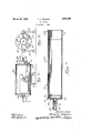
- FIG. 3 is enlargeddetail sectionof the improved formof retort embodying my invention, and with the endcover removed.
- a cover 16' is suitably engaged for detachable connection by clamps 16a, 16a to the projecting end 14 of the'retort to permit entrance andremoval of the material being carburized.
- V c Details of my improved retort areshown in Figure 3, in which it will be seen that the cylindrical body 12a is hollow throughout its length, and with its walls of substantially uniform: thickness, excepting for a. slightly reduced end portion 14 which extends beyond the furnace 10, and has afiange 18 to, which the cover is clamped.
- the cylindri'cal body is made by a centrifugal cast ing process, which process permits the for- ⁇ mation of. relatively thin walls of; uniform thickness, impervious to the escape of gases.
- the cylinder is cast with open ends, and is which has a cylindrical 'flange2lfittingclose- 1y in'the end ofthe cylinder, and a project- -,-in g shoulder 22 against which the end of the cylinder abuts.
- the parts are preferably se- ,ni'on bearing 13 integral therewith, and a reduced portion 13a which is adapted'to carry a suitable drive pinion (not shown) by which the retort is rotated during operation in the usual manner.
- a passage 25 extends axially through the trunnion bearing as shown, to conduct the carburizing gas to the interior of the retort.
- arotary retort made up of a cylindrical body section and a separately cast end section including "an axially PIOJGCtlI'lg trunnion bearing and a drive connection for rotating said retort,
- said end section having an annular flange fitting in supporting engagementwithin one end of said body section, and a contiguous upstanding shoulder against'which the end surface of said body section abuts and is Welded thereto in a continuous line around the periphery of said retort.
- a rotary retort made up of a cylindrical centrifugally cast body section having walls of'substantially uniform thicknessthrough itslength, "anda sep'arately cast end sectionincludi'ng an axially projecting trunnion bearing and a drive c'onnection for rotating said retort,
- said end section havinganannular flange fitting in'supportin'g engagement within one end of said body section, and a contiguous upstanding shoulder against which the end surface of said body section abuts and is 'welded thereto in a continuous line around the periphery of said retort.
- a rotary retort which consists informing separately a bylindrical centrifugally cast body section having walls of substantially uniform thickness throughout its length, and a cast end section having an axially projecting trunnion bearing andan annular supporting flange, and then fitting one end of said body section in supporting engagement upon said supporting flangeand Vwelding the parts together in a continuous line around the extreme end of said body section.
Landscapes
- Chemical & Material Sciences (AREA)
- Engineering & Computer Science (AREA)
- Physics & Mathematics (AREA)
- Thermal Sciences (AREA)
- Crystallography & Structural Chemistry (AREA)
- Mechanical Engineering (AREA)
- Materials Engineering (AREA)
- Metallurgy (AREA)
- Organic Chemistry (AREA)
- Muffle Furnaces And Rotary Kilns (AREA)
Description
March 29, 1932. Z|EGLER I 1,851,029
GAS RETORT Filed Feb. 4, 1,931
N Java 7110;-
F m (K Zae Z02 was; @ZZWM Patented Mar. 29, 193 2 UNITED sTA'r-ss COMPANY, OF LIMA, orrro, a'conro mrron or OHIO FRANKK. ZIEGLER, or SPRINGFIELD, 01110, hssre'noia TO THE 61:10 sinner Founnnx GAS 3mm Application filed February 4," ',19s1=. :--s'eria rim-513,280.
This invention relates to improvements in rotary carburzing retorts, and more particu-v larly to retorts of the character described,
utilized in the gas carburizing process, and
heretofore been cast of a high heat-resisting 10 alloy, and in their commercial form have pre sented considerable difiiculties in manufacture. This is due largely to the fact that the castings must be impervious to the gases used in the gas carburizing process, as well as the 15 gases of combustion used for heating the retort.
Heretofore the retorts have been cast in a single piece, including the cylindrical body portion and the end trunnion bearing extension. Such castings, however, present certain difliculties in that it is practically impossible to place and maintain the core so I that the wall sections are of uniform section.
Furthermore, there is a large loss of such wherein the cylindrical part and trunnion end piece are made separately, the first part by a centrifugal moulding process and the end piece by sandcasting, and the two parts at one end to form aretort which is much lighter in weight, making possible quicker penetration of heat which is applied to the outside of the retort, and requiring less power to drive the retort, than is possible with the older forms of integral sand-cast retorts. I
The invention may best be understood by which:
Figure 1 is a side view of a carburizing apparatus, illustrating the manner in which the retort is employed.
Figure 2 is an end view of the apparatus shown in Figure 1.
are welded together with a substantial joint Supported at one end on a trunnion piece 20 reference to the accompanying drawings, in
i Figure 3 is enlargeddetail sectionof the improved formof retort embodying my invention, and with the endcover removed.
Referring now to details of the embodiment i.
of my inventionillustrated' in the drawings, a carburizing furnace is indicated at10,;be-
, ing mounted'bodilyon trunnions,11,'11, and having a retort 12 having its cylindrical body 1221 extending longitudinally therethrough. Saidretort is provided with a reduced trun- -nion bearing 13 atone end thereof, and hav ing its opposite cylindrical end l lprojecting from the opposite-end of the furnace ,and-supp ortedeon a pair of bearing rollers 15,15.. A cover 16' is suitably engaged for detachable connection by clamps 16a, 16a to the projecting end 14 of the'retort to permit entrance andremoval of the material being carburized. A pipe 17extends through the cover 16' for exhausting the, gas ;-from,the retort. V c Details of my improved retort areshown in Figure 3, in which it will be seen that the cylindrical body 12a is hollow throughout its length, and with its walls of substantially uniform: thickness, excepting for a. slightly reduced end portion 14 which extends beyond the furnace 10, and has afiange 18 to, which the cover is clamped. The cylindri'cal body is made by a centrifugal cast ing process, which process permits the for- }mation of. relatively thin walls of; uniform thickness, impervious to the escape of gases.
The cylinder is cast with open ends, and is which has a cylindrical 'flange2lfittingclose- 1y in'the end ofthe cylinder, and a project- -,-in g shoulder 22 against which the end of the cylinder abuts. The parts are preferably se- ,ni'on bearing 13 integral therewith, and a reduced portion 13a which is adapted'to carry a suitable drive pinion (not shown) by which the retort is rotated during operation in the usual manner. A passage 25 extends axially through the trunnion bearing as shown, to conduct the carburizing gas to the interior of the retort.
It will now be understood that by the twopart construction described, it is possible to obtain the benefits of the centrifugal casting process, which process, however, could not be utilized to produce the entire retort in a single piece. By the novel method of support and j ointure with the separate endbearing piece as described, a much lighter," more impervious and generally more satisfactory retort is obtained.
Although I have shown and described one particular embodiment of my invention, it willbe'understood that I do not wish to be limited to the exact construction shown and described, but that various changes and modifications may be made without departingfrom the spirit and scope of my invention.
I claim as my invention:
1. As an article of manufacture, arotary retort made up of a cylindrical body section and a separately cast end section including "an axially PIOJGCtlI'lg trunnion bearing and a drive connection for rotating said retort,
said end section having an annular flange fitting in supporting engagementwithin one end of said body section, anda contiguous upstanding shoulder against'which the end surface of said body section abuts and is Welded thereto in a continuous line around the periphery of said retort.
'2. As an article of manufacture, a rotary retort made up of a cylindrical centrifugally cast body section having walls of'substantially uniform thicknessthrough itslength, "anda sep'arately cast end sectionincludi'ng an axially projecting trunnion bearing and a drive c'onnection for rotating said retort,
said end section havinganannular flange fitting in'supportin'g engagement within one end of said body section, and a contiguous upstanding shoulder against which the end surface of said body section abuts and is 'welded thereto in a continuous line around the periphery of said retort.
3. The method of making a rotary retort, which consists informing separately a bylindrical centrifugally cast body section having walls of substantially uniform thickness throughout its length, and a cast end section having an axially projecting trunnion bearing andan annular supporting flange, and then fitting one end of said body section in supporting engagement upon said supporting flangeand Vwelding the parts together in a continuous line around the extreme end of said body section.
Signed at Springfield, Ohio, this 31st day of January, 1931.
FRANK K. JZIEGLER.
Priority Applications (1)
| Application Number | Priority Date | Filing Date | Title |
|---|---|---|---|
| US513280A US1851029A (en) | 1931-02-04 | 1931-02-04 | Gas retort |
Applications Claiming Priority (1)
| Application Number | Priority Date | Filing Date | Title |
|---|---|---|---|
| US513280A US1851029A (en) | 1931-02-04 | 1931-02-04 | Gas retort |
Publications (1)
| Publication Number | Publication Date |
|---|---|
| US1851029A true US1851029A (en) | 1932-03-29 |
Family
ID=24042592
Family Applications (1)
| Application Number | Title | Priority Date | Filing Date |
|---|---|---|---|
| US513280A Expired - Lifetime US1851029A (en) | 1931-02-04 | 1931-02-04 | Gas retort |
Country Status (1)
| Country | Link |
|---|---|
| US (1) | US1851029A (en) |
-
1931
- 1931-02-04 US US513280A patent/US1851029A/en not_active Expired - Lifetime
Similar Documents
| Publication | Publication Date | Title |
|---|---|---|
| US1851029A (en) | Gas retort | |
| US2792214A (en) | Furnace lining | |
| US890314A (en) | Annealing-furnace. | |
| FR2370795A1 (en) | PROCESS FOR TEMPERING A TOOTHED WHEEL | |
| US2002972A (en) | Apparatus for making portland cement | |
| US2502204A (en) | Annealing furnace | |
| US2002877A (en) | Welding equipment and method of welding | |
| US2602653A (en) | Bright strip annealing apparatus | |
| CN112680555B (en) | A blast furnace residual iron discharge structure, blast furnace and blast furnace residual iron discharge method | |
| US1808145A (en) | Brass-melting apparatus | |
| US2848210A (en) | Dehydrating gypsum or the like | |
| JPS5270914A (en) | Heat treatment of pipe | |
| CA1111640A (en) | Cooled nozzle for blowing gases in a multen metal bath | |
| US1812320A (en) | Annealing | |
| GB764779A (en) | Improvements in or relating to rotary furnaces | |
| US1084991A (en) | Furnace for refining metals. | |
| US1033815A (en) | Apparatus for case-hardening and other metal treatment. | |
| US2848209A (en) | Dehydrating apparatus | |
| SU591528A1 (en) | Method of chemical/thermal treatment of tubes | |
| SU92012A1 (en) | Method for the production of steel in an open-hearth furnace | |
| US1692842A (en) | Method of manufacturing black-heart malleable cast iron from white cast iron | |
| SU595067A1 (en) | Method of making reinforced castings | |
| SU920077A2 (en) | Installation for diffusion chrome-plate | |
| SU506466A1 (en) | Refrigeration plate metallurgical unit | |
| SU102595A2 (en) | Vacuum unit for degassing and removal of harmful impurities from liquid metals and alloys |