US185016A - Improvement in compensating-pendulums - Google Patents
Improvement in compensating-pendulums Download PDFInfo
- Publication number
- US185016A US185016A US185016DA US185016A US 185016 A US185016 A US 185016A US 185016D A US185016D A US 185016DA US 185016 A US185016 A US 185016A
- Authority
- US
- United States
- Prior art keywords
- ball
- pendulums
- improvement
- compensating
- nut
- Prior art date
- Legal status (The legal status is an assumption and is not a legal conclusion. Google has not performed a legal analysis and makes no representation as to the accuracy of the status listed.)
- Expired - Lifetime
Links
Images
Classifications
-
- G—PHYSICS
- G04—HOROLOGY
- G04B—MECHANICALLY-DRIVEN CLOCKS OR WATCHES; MECHANICAL PARTS OF CLOCKS OR WATCHES IN GENERAL; TIME PIECES USING THE POSITION OF THE SUN, MOON OR STARS
- G04B17/00—Mechanisms for stabilising frequency
- G04B17/20—Compensation of mechanisms for stabilising frequency
- G04B17/22—Compensation of mechanisms for stabilising frequency for the effect of variations of temperature
- G04B17/225—Compensation of mechanisms for stabilising frequency for the effect of variations of temperature with pendulums
Definitions
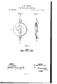
- FIG. 1 is a front view of the pendulum ball or weight.
- Fig. 2 is a vertical section on line X.
- Fig. 3 is a horizontal section on line Y.
- the variations of the length of the suspendingrod or pendulum-wire B, due to different temperatures, are compensated by placing between the ball A and its supporting and regulating nut B a piece of hard rubber, (l, which, being secured to the ball A by the screw, pin, or projection G at one end, and resting upon the regulating-nut B at the other, keeps the center of gravity of the ball A at a uniform distance from the point of suspension or commencement of motion.
- the length of the hard rubber between G and B is proportioned to the length of the metal from B to the point of suspension, exactly in the inverse ratio of the expansions of the two substances at equal temperatures.
- the ball A and rubber O are suspended by the wire B and regulatingscrew and nut B in the usual manner.
- wire B is a portion of the suspending-rod, and the loop and corresponding hook may be dispensed with,and the nut B screwed upon the rod itself, if desired.
- the nut 13 is provided with a set-screw, B to prevent accidental displacement after the clock has been regulated.
- the ball A has a metallic sheath or case, A, which protects and guides the rubber G and wire B.
- the ball A is shown annular in form, but may be made of any suitable form or ma terial.
- the hard rubber C may be flat, as shown, or square or cylindrical, solid or hollow, as may be preferred.
Landscapes
- Engineering & Computer Science (AREA)
- Metallurgy (AREA)
- Physics & Mathematics (AREA)
- General Physics & Mathematics (AREA)
- Compositions Of Macromolecular Compounds (AREA)
Description
UNITED STATES PATENT OFFICE.
EBEN M. GORWIN, OF BARRY, ILLINOIS.
IMPROVEMENT IN COMPENSATlNG-PENDULUMS.
Specification forming part of Letters Patent No. 185,016, dated December 5, 1876; application filed October 30, 1876.
To all whom it may concern:
Be it known that I, EBEN MERToN 00R- WIN, of Barry, in the county of Pike and State of Illinois, have invented a new and Improved Compensating-Bendulum, of which the following is a specification Figure 1 is a front view of the pendulum ball or weight. Fig. 2 is a vertical section on line X. Fig. 3 is a horizontal section on line Y.
Similar letters of reference indicate correspondiu g parts. t
In this invention the variations of the length of the suspendingrod or pendulum-wire B, due to different temperatures, are compensated by placing between the ball A and its supporting and regulating nut B a piece of hard rubber, (l, which, being secured to the ball A by the screw, pin, or projection G at one end, and resting upon the regulating-nut B at the other, keeps the center of gravity of the ball A at a uniform distance from the point of suspension or commencement of motion.
For this purpose the length of the hard rubber between G and B is proportioned to the length of the metal from B to the point of suspension, exactly in the inverse ratio of the expansions of the two substances at equal temperatures. The ball A and rubber O are suspended by the wire B and regulatingscrew and nut B in the usual manner. The
wire B is a portion of the suspending-rod, and the loop and corresponding hook may be dispensed with,and the nut B screwed upon the rod itself, if desired. The nut 13 is provided with a set-screw, B to prevent accidental displacement after the clock has been regulated. The ball A has a metallic sheath or case, A, which protects and guides the rubber G and wire B. The ball A is shown annular in form, but may be made of any suitable form or ma terial.
The hard rubber C may be flat, as shown, or square or cylindrical, solid or hollow, as may be preferred.
Having thus described my invention, Iclaim as new and desire to secure by Letters Patent- 1. The combination of the hard rubber O with the suspending-rod B and ball A, sub stantially as and for the purposes set forth.
2. The combination of the hard rubber G with the ball A and protecting-sheath A, substantially as herein shown and described.
3. The combination of the set-screw B with the regulating-nut B and wire B, as herein shown and described.
EBEN MERTON GORWIN.
Witnesses:
GEo. A. FERGUSON, O. R. EMERSON.
Applications Claiming Priority (1)
| Application Number | Priority Date | Filing Date | Title |
|---|---|---|---|
| US185016TA | 1876-10-30 | 1876-10-30 |
Publications (1)
| Publication Number | Publication Date |
|---|---|
| US185016A true US185016A (en) | 1876-12-05 |
Family
ID=32848720
Family Applications (1)
| Application Number | Title | Priority Date | Filing Date |
|---|---|---|---|
| US185016D Expired - Lifetime US185016A (en) | 1876-10-30 | 1876-10-30 | Improvement in compensating-pendulums |
Country Status (1)
| Country | Link |
|---|---|
| US (1) | US185016A (en) |
-
1876
- 1876-10-30 US US185016D patent/US185016A/en not_active Expired - Lifetime
Similar Documents
| Publication | Publication Date | Title |
|---|---|---|
| US185016A (en) | Improvement in compensating-pendulums | |
| US5017A (en) | Self-adjusting- pendulum | |
| US584871A (en) | Telephone-bracket | |
| US622073A (en) | Tilting-chair | |
| US283280A (en) | Cornice-hook | |
| US334958A (en) | Pendulum | |
| US215729A (en) | Improvement in adjustable ladder-hooks | |
| US173285A (en) | Improvement in pendulum-balls | |
| US196702A (en) | Improvement in clock-pendulums | |
| US184972A (en) | Improvement in clock-movements | |
| US292282A (en) | Apparatus for adjusting the beat of pendulum-clocks | |
| US396095A (en) | Compensation pendulum | |
| US200386A (en) | Improvement in weighing-scales | |
| US519236A (en) | William isaac castleman | |
| US514122A (en) | John c | |
| US465246A (en) | Spring-scale | |
| US189853A (en) | Improvement in tripods for rock-drills | |
| US120385A (en) | Improvement in compensation-pendulums | |
| US627041A (en) | Curtain-support | |
| US27684A (en) | Coktstructiolsr of clock-weights | |
| US200749A (en) | Improvement in spring draft-tugs | |
| US120608A (en) | Improvement in construction of arches | |
| US161880A (en) | Improvement in billiard-cushions | |
| US490879A (en) | Henry e | |
| US515855A (en) | Otto babtel |