US178564A - Feedeeick h - Google Patents
Feedeeick h Download PDFInfo
- Publication number
- US178564A US178564A US178564DA US178564A US 178564 A US178564 A US 178564A US 178564D A US178564D A US 178564DA US 178564 A US178564 A US 178564A
- Authority
- US
- United States
- Prior art keywords
- drum
- roller
- sides
- mill
- tread
- Prior art date
- Legal status (The legal status is an assumption and is not a legal conclusion. Google has not performed a legal analysis and makes no representation as to the accuracy of the status listed.)
- Expired - Lifetime
Links
- 239000000463 material Substances 0.000 description 12
- QSHDDOUJBYECFT-UHFFFAOYSA-N mercury Chemical compound [Hg] QSHDDOUJBYECFT-UHFFFAOYSA-N 0.000 description 7
- 229910052753 mercury Inorganic materials 0.000 description 7
- XLYOFNOQVPJJNP-UHFFFAOYSA-N water Substances O XLYOFNOQVPJJNP-UHFFFAOYSA-N 0.000 description 6
- 238000005267 amalgamation Methods 0.000 description 3
- 230000000284 resting effect Effects 0.000 description 3
- 229910052751 metal Inorganic materials 0.000 description 2
- 239000002184 metal Substances 0.000 description 2
- 239000007787 solid Substances 0.000 description 2
- 239000012141 concentrate Substances 0.000 description 1
- 238000007599 discharging Methods 0.000 description 1
- 238000001035 drying Methods 0.000 description 1
- 230000000694 effects Effects 0.000 description 1
- 150000002739 metals Chemical class 0.000 description 1
- 238000010298 pulverizing process Methods 0.000 description 1
Images
Classifications
-
- B—PERFORMING OPERATIONS; TRANSPORTING
- B02—CRUSHING, PULVERISING, OR DISINTEGRATING; PREPARATORY TREATMENT OF GRAIN FOR MILLING
- B02C—CRUSHING, PULVERISING, OR DISINTEGRATING IN GENERAL; MILLING GRAIN
- B02C17/00—Disintegrating by tumbling mills, i.e. mills having a container charged with the material to be disintegrated with or without special disintegrating members such as pebbles or balls
- B02C17/18—Details
- B02C17/24—Driving mechanisms
Definitions
- N-PEYERS PHOTO-LITHOGRAPHER, wASmNGToN, a C4 FREDERICK H. SMITH, OF BALTIMORE, MARYLAND.
- the object of my invention is to produce a crushing-mill or amalgamating-mill, ora crushing and amalgamating mill, for the pulverization of ores or other material, or for the amalgamation of mercury, 850., with metals, or for the pulvefication of ores and the amalgamation of their metallic portions with mercury, &c., by either wet or dry process.
- My invention consists of a mill composed of a free-rt nning .roller inside of a drum, the rim of the drum resting on bearing or tread wheels, the whole mill revolving by means of power applied either directly to the drum or. indirectly through the tread-wheels, thereby causing the roller to roll on the inner surface of therim of the drum and pulverize any material placed in the drum 5 and, by the introduction of mercury, the material is pressed into contact with the mercury, resulting in the thorough amalgamation of the mercury and the metallic portion of the pulverized material.
- One or more holes, closed by screw or other plugs, are made in the rim of the drum, for the charging and discharging of the mercury, water, or other material when the mill is to be operated on the system of separate charges; and if the mill is to be operated on the continuous system, central openings are also made in the sides of the drum, through which the materials and a current or supply of air, water, or steam, or water-and steam, is passed, either running in at one side of the drum and out at the other through an outletpipe, or running in at one or both sides and out again through spaces in the central openings not occupied or covered up by the inlet pipes or spouts.
- Figure l is a longitudinal section of the mill, in which A is the rim of the drum. B is the roller. 0 O are movable sides to the drum. D D are the tread-wheels. E E are the central openings in the sides of the drum, and H is the hole in the rim of the drum. Fi 2 is a transverse section through the mill, the same letters referrin g to similar parts in both figures.
- the drum has no axle, so that a crushingroller of as large a diameter as desired may be used.
- the roller is practically solid, enabling me to concentrate great weight on a very limited tread, thus obtaining the crushin g effect of a given roller-weight on the sm allest amount of ore at any one time.
- a very much smaller outlay for the outer drum or shell is required, and I make altogether a much more compact machine than has heretofore been produced.
- the sides of the drum can be straight or may be bulged outward to admit of a free circulation of the currents, or to allow the banked-up material behind the roller to work around in front of it again.
- the sides of the roller can be made concave or convex or bulging, and the roller may have radial holes running from its periphery through to the sides or to a central hole, for the same purpose of facilitating the circulation of the currents or materials. Holes may run through the roller in other suit-able directions for the same purpose.
- the roller can be circular or oblong or elliptical to increase its crushing power, and the roller tread-surface can be flat or rounded or angular or grooved or toothed, with or without similar conformation of the inner surface of the rim of the drum.
- the roller may be of polygonal shape, with-curved or flat facets, connected by-eorners or curves of less radius.
- the roller can be in one piece, or in concentric rings or segments or slices, to facilitate transportation or handling.
- the rim of the drum can be made in one piece, with movable sides to admit the roller, or it may be made in segments or slices, and built up around the roller; or it may be thus made in pieces, and also have the movable sides.
- the tread-wheels can be of any number, but preferably two. One can be used under the center of the drum, with small steady-wheels at other points. They should be, as nearly as practicable, under the working center of the pressure of the roller and belted together.
- the power can be applied by cogs or belts on the drum or on the tread-wheels, or by the shafts of the tread-wheels, which can then revolve the drum by traction or friction, or by a belt around both drum and tread-wheels.
- the feed of ore or other material can be carried onto the drum by the current of air, water, or steam, or water and steam, or can be inserted directly into the side holes or rim holes, and the mercury withdrawn through the rimholes for retortin g or for security during stoppage.
- the current can be carried in under natural flowavhen water is used, or under pressure when air or steam is used, and also when water is used.
- the inlet and outlet pipes should be nozzled with soft metal or material to take the wear off the sides of the drum, and also to obtain a reasonably tight joint; and the outlet-pipe may be carried upward,'in order that such escaping material as is not fully worked may fall back into the drum, and for this purpose the outlet-pipe may be funnelshaped, or pass into or through a funnel, or
- any other means used to produce dead-angles passes in through one side and out at the other; but when the current passes in through one or both sides and out again through the same side the diversion is not necessary.
- the inlet and outlet are both desired on the same side of the drum, the central opening in one side is to be closed, and there may be two pipes inserted in the same nozzle; or the outlet may go 011 through the space left for that purpose between the inlet pipe or spout and the sides of the hole in the drum, as in the case of feeding in through both sides of the drum.
Landscapes
- Engineering & Computer Science (AREA)
- Food Science & Technology (AREA)
- Crushing And Grinding (AREA)
Description
F. H. SMITH.
CRUSHINGMILL; No. 178.564, Patented June13,1876
mfiwmes I InVen/ZZr:
N-PEYERS, PHOTO-LITHOGRAPHER, wASmNGToN, a C4 FREDERICK H. SMITH, OF BALTIMORE, MARYLAND.
IPROVEMENT IN CRU$HING-MILLS.
Specification forming part of Letters Patent No. 17$,564, dated June 13, 1876; application filed March 9, 1876.
To all whom it may concern:-
Be it known that I, FREDERICK H. SMITH, of Baltimore, Maryland, have in vented certain new and useful Improvements in Crushing- Mills or Amalgamating-Mills, or Crushing and Amalgamating Mills, of which the following is a specification;
The object of my invention is to produce a crushing-mill or amalgamating-mill, ora crushing and amalgamating mill, for the pulverization of ores or other material, or for the amalgamation of mercury, 850., with metals, or for the pulvefication of ores and the amalgamation of their metallic portions with mercury, &c., by either wet or dry process.
My invention consists of a mill composed of a free-rt nning .roller inside of a drum, the rim of the drum resting on bearing or tread wheels, the whole mill revolving by means of power applied either directly to the drum or. indirectly through the tread-wheels, thereby causing the roller to roll on the inner surface of therim of the drum and pulverize any material placed in the drum 5 and, by the introduction of mercury, the material is pressed into contact with the mercury, resulting in the thorough amalgamation of the mercury and the metallic portion of the pulverized material.
One or more holes, closed by screw or other plugs, are made in the rim of the drum, for the charging and discharging of the mercury, water, or other material when the mill is to be operated on the system of separate charges; and if the mill is to be operated on the continuous system, central openings are also made in the sides of the drum, through which the materials and a current or supply of air, water, or steam, or water-and steam, is passed, either running in at one side of the drum and out at the other through an outletpipe, or running in at one or both sides and out again through spaces in the central openings not occupied or covered up by the inlet pipes or spouts.
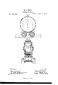
Figure l is a longitudinal section of the mill, in which A is the rim of the drum. B is the roller. 0 O are movable sides to the drum. D D are the tread-wheels. E E are the central openings in the sides of the drum, and H is the hole in the rim of the drum. Fi 2 is a transverse section through the mill, the same letters referrin g to similar parts in both figures.
The drum has no axle, so that a crushingroller of as large a diameter as desired may be used. The roller is practically solid, enabling me to concentrate great weight on a very limited tread, thus obtaining the crushin g effect of a given roller-weight on the sm allest amount of ore at any one time. At the same time a very much smaller outlay for the outer drum or shell is required, and I make altogether a much more compact machine than has heretofore been produced.
The sides of the drum can be straight or may be bulged outward to admit of a free circulation of the currents, or to allow the banked-up material behind the roller to work around in front of it again. The sides of the roller can be made concave or convex or bulging, and the roller may have radial holes running from its periphery through to the sides or to a central hole, for the same purpose of facilitating the circulation of the currents or materials. Holes may run through the roller in other suit-able directions for the same purpose. The roller can be circular or oblong or elliptical to increase its crushing power, and the roller tread-surface can be flat or rounded or angular or grooved or toothed, with or without similar conformation of the inner surface of the rim of the drum. In lieu of being circular, oblong, or elliptical, the roller may be of polygonal shape, with-curved or flat facets, connected by-eorners or curves of less radius.
The roller can be in one piece, or in concentric rings or segments or slices, to facilitate transportation or handling.
The rim of the drum can be made in one piece, with movable sides to admit the roller, or it may be made in segments or slices, and built up around the roller; or it may be thus made in pieces, and also have the movable sides.
The tread-wheels can be of any number, but preferably two. One can be used under the center of the drum, with small steady-wheels at other points. They should be, as nearly as practicable, under the working center of the pressure of the roller and belted together. The power can be applied by cogs or belts on the drum or on the tread-wheels, or by the shafts of the tread-wheels, which can then revolve the drum by traction or friction, or by a belt around both drum and tread-wheels. The feed of ore or other material can be carried onto the drum by the current of air, water, or steam, or water and steam, or can be inserted directly into the side holes or rim holes, and the mercury withdrawn through the rimholes for retortin g or for security during stoppage. The current can be carried in under natural flowavhen water is used, or under pressure when air or steam is used, and also when water is used. The inlet and outlet pipes should be nozzled with soft metal or material to take the wear off the sides of the drum, and also to obtain a reasonably tight joint; and the outlet-pipe may be carried upward,'in order that such escaping material as is not fully worked may fall back into the drum, and for this purpose the outlet-pipe may be funnelshaped, or pass into or through a funnel, or
i any other means used to produce dead-angles passes in through one side and out at the other; but when the current passes in through one or both sides and out again through the same side the diversion is not necessary.
WVhen the inlet and outlet are both desired on the same side of the drum, the central opening in one side is to be closed, and there may be two pipes inserted in the same nozzle; or the outlet may go 011 through the space left for that purpose between the inlet pipe or spout and the sides of the hole in the drum, as in the case of feeding in through both sides of the drum.
Having described my invention ,what I claim, and desire to secure by Letters Patent, is as follows: 1
A crushing-mill or amalgamating-mill, or a crushing and amalgamating mill, composed of a vertical revolving drum, without internal axle, inclosing a free circular or oblong or polygonal, and practically solid, roller, and resting and revolving on, or resting on and revolved by, one or more tread-wheels, and having suitable inlet and outlet apertures in its rim or sides for the introduction and discharge of materials and currents, substantially as set forth.
In testimony whereof I have hereunto signed my name this 8th day of March, A. D. 1876.
FRED. H. SMITH. Witnesses:
E. NUGENT, (J. W. BAYLY.
Publications (1)
| Publication Number | Publication Date |
|---|---|
| US178564A true US178564A (en) | 1876-06-13 |
Family
ID=2247971
Family Applications (1)
| Application Number | Title | Priority Date | Filing Date |
|---|---|---|---|
| US178564D Expired - Lifetime US178564A (en) | Feedeeick h |
Country Status (1)
| Country | Link |
|---|---|
| US (1) | US178564A (en) |
Cited By (5)
| Publication number | Priority date | Publication date | Assignee | Title |
|---|---|---|---|---|
| US2484873A (en) * | 1945-11-16 | 1949-10-18 | Celanese Corp | Roller support for ball mills |
| US2525663A (en) * | 1947-09-27 | 1950-10-10 | Us Stoneware Co | Material-tumbling assembly |
| US2702217A (en) * | 1950-05-29 | 1955-02-15 | Monolith Portland Cement Compa | Mounting means for rotary mill or drier construction |
| US2873072A (en) * | 1957-06-13 | 1959-02-10 | Us Stoneware Co | Jar mill |
| US3987969A (en) * | 1975-03-10 | 1976-10-26 | Kvaerner Brug A/S | Method and disc mill for grinding of material |
-
0
- US US178564D patent/US178564A/en not_active Expired - Lifetime
Cited By (5)
| Publication number | Priority date | Publication date | Assignee | Title |
|---|---|---|---|---|
| US2484873A (en) * | 1945-11-16 | 1949-10-18 | Celanese Corp | Roller support for ball mills |
| US2525663A (en) * | 1947-09-27 | 1950-10-10 | Us Stoneware Co | Material-tumbling assembly |
| US2702217A (en) * | 1950-05-29 | 1955-02-15 | Monolith Portland Cement Compa | Mounting means for rotary mill or drier construction |
| US2873072A (en) * | 1957-06-13 | 1959-02-10 | Us Stoneware Co | Jar mill |
| US3987969A (en) * | 1975-03-10 | 1976-10-26 | Kvaerner Brug A/S | Method and disc mill for grinding of material |
Similar Documents
| Publication | Publication Date | Title |
|---|---|---|
| US178564A (en) | Feedeeick h | |
| US2700511A (en) | Ore fiberizing machine | |
| US1200104A (en) | Ore crusher and concentrator. | |
| US1187932A (en) | Machine for refining paper-stock. | |
| US204945A (en) | Improvement in pulverizing apparatus | |
| US614074A (en) | Henry banfield | |
| US178266A (en) | Improvement in ore-pulverizers | |
| US379943A (en) | Vibglstia | |
| US1444485A (en) | Ore concentrator | |
| US395140A (en) | Grin ding-mill | |
| US245848A (en) | And amalgamating ores | |
| US387539A (en) | raymond | |
| US3670973A (en) | Crusher | |
| US201347A (en) | Improvement in mills for pulverizing | |
| US742982A (en) | Crushing and pulverizing mill. | |
| US832801A (en) | Ore-pulverizing machine. | |
| US1747922A (en) | Method and apparatus for pulverizing materials | |
| US403215A (en) | Attrition-mill | |
| US440072A (en) | Grinding-mill | |
| US150217A (en) | Improvement in apparatus for pulverizing plumbago | |
| US291367A (en) | luckenbach | |
| US234027A (en) | Ore-grinding mill | |
| US166743A (en) | Improvement in wet and dry ore crushers | |
| US217075A (en) | Improvement in crushing and pulverizing mills | |
| US395580A (en) | Kison |