US1782575A - Extractor cover - Google Patents
Extractor cover Download PDFInfo
- Publication number
- US1782575A US1782575A US337402A US33740229A US1782575A US 1782575 A US1782575 A US 1782575A US 337402 A US337402 A US 337402A US 33740229 A US33740229 A US 33740229A US 1782575 A US1782575 A US 1782575A
- Authority
- US
- United States
- Prior art keywords
- cover
- extractor
- bowl
- fabric
- reinforcing
- Prior art date
- Legal status (The legal status is an assumption and is not a legal conclusion. Google has not performed a legal analysis and makes no representation as to the accuracy of the status listed.)
- Expired - Lifetime
Links
- 239000004744 fabric Substances 0.000 description 14
- 230000003014 reinforcing effect Effects 0.000 description 11
- 239000010985 leather Substances 0.000 description 5
- 239000002184 metal Substances 0.000 description 4
- DOQPXTMNIUCOSY-UHFFFAOYSA-N [4-cyano-4-(3,4-dimethoxyphenyl)-5-methylhexyl]-[2-(3,4-dimethoxyphenyl)ethyl]-methylazanium;chloride Chemical compound [H+].[Cl-].C1=C(OC)C(OC)=CC=C1CCN(C)CCCC(C#N)(C(C)C)C1=CC=C(OC)C(OC)=C1 DOQPXTMNIUCOSY-UHFFFAOYSA-N 0.000 description 2
- 229940116800 covera Drugs 0.000 description 2
- 238000003780 insertion Methods 0.000 description 2
- 230000037431 insertion Effects 0.000 description 2
- 239000000463 material Substances 0.000 description 2
- 239000002131 composite material Substances 0.000 description 1
- 238000010981 drying operation Methods 0.000 description 1
- 239000007788 liquid Substances 0.000 description 1
- 230000013011 mating Effects 0.000 description 1
- 235000013372 meat Nutrition 0.000 description 1
- 230000004048 modification Effects 0.000 description 1
- 238000012986 modification Methods 0.000 description 1
- 238000000926 separation method Methods 0.000 description 1
Images
Classifications
-
- D—TEXTILES; PAPER
- D06—TREATMENT OF TEXTILES OR THE LIKE; LAUNDERING; FLEXIBLE MATERIALS NOT OTHERWISE PROVIDED FOR
- D06F—LAUNDERING, DRYING, IRONING, PRESSING OR FOLDING TEXTILE ARTICLES
- D06F37/00—Details specific to washing machines covered by groups D06F21/00 - D06F25/00
- D06F37/02—Rotary receptacles, e.g. drums
- D06F37/12—Rotary receptacles, e.g. drums adapted for rotation or oscillation about a vertical axis
- D06F37/18—Doors or covers; Securing means therefor
Definitions
- This inve-ntion relates to covers for extractors such as are used laundries, dry clean- 111g plants, and the like, wher'emthe articles to becleaned arelrotated at high speed in a drying operation.
- I i 1 A principal object is to provide a flexible t fabric cover adapted to be held in the top of anextractor bowlin such a'manner that the articleswvill be retainedin -the bowl and prevented from removal therefrom while theextractor is in operation.
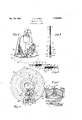
- Fig. 1 is atop plan view'of an extractor cover embodying my improvements.
- Fig. 2 is a fragmentary perspective view of a well known for-1n ofextracto-r with my cover; shown-"in operative ⁇ pos ition therein.
- the flexible ci' r cular cover A is adapted to be supported in an extractor B so that the peripherythereof will underlie the annular top Cof the extrac tor bowl B.
- Said bowl is covered by aretaining ring C- and a perforated cover composed of mating members D, 'D, as shown in Fig. 2.
- the extractor bowl B is rotated by means of a power driven vertical shaft 'E, and the cover A is rotatedjwith the bowl.
- e outer margin ofthe top sheet l is bent down over the outer edgeof and underthe marginal portionyof the sheet 2, as at 7, and is st tched at. 8.
- the lowerv sheet 2. is bent around' the inner edge of the uppersheet l and thence over said sheet at 9, and the outer edge thereof. is underturned as at 10, thus providing three lami'nations of material adjacent the central aperture 11in the cover, through which the shaft E is-adapted to ex tend when the cover is in use.
- the inner edge of the composite coverA is substantially reinforced by means of a binding stripf12 of leatheror the like, the
- coverA is splitin a raldia'l line at 18 and the portions of the coveron opposite sides of theline of separation are reinforced by fabric strips 19 and 20. which are stitched to the top. sides of thesheetjl. Also binding strips 21 and 22 are attached ⁇ to theadjacent edges and a flap 23. is attached tooneside and adapted to underlie the other side of the-(cover a the aw ing-the c verthe cover is in use, the ends are adapted to be fastened together by means of suitable snap fasteners, as at 2a, which engage rings 25, or otherwise.
- the rings are held in heavy leather straps 26, the end portions of which are folded over one upon the other, and thin metal straps 27 are inserted therebetween, as shown in Fig. fl.
- the metal straps 27 are riveted to the leather straps 26 and the leather straps are riveted to the cover by a. pair or more of rivets 29.
- the metal reinforcing straps 27 prevent the rivets from tearing out and add durability to the cover.
- the snaps 9A are similarly attached to the opposite end of the cover by means of leather straps 30, metal straps 31, and rivets 32 and 33.
- the opening 18 in the cover permits the ready insertion of the cover in the bowl of the extractor and the removal therefrom at Will.
- the snap fasteners 24 areengagcd with the rings 25 and the covers D. D are replaced in operative position.
- the cover A will serve to neatly hold the articles in the bowl during a liquid extracting operation.
- the flexibility of the cover facilitates the insertion and removal of the cover in and from position of use respectively.
- cover is reinforced at points where the greatest wear is occasioned in its use, and the cover constructed as shown and described herein is more durable than other covers heretofore known and used.
- a device of the character described coin prising a flexible fabric cover of circular form and having a radial split and a central opening therein, means for reinforcing the margin of the cover at said opening, and means for detachably connecting the edges of the cover adjacent said split.
- A. device as characterized. in claim l including a flap attached to one of the edges of the cover adjacent the split and underlying the adjacent portion when the edges are attached together.
- An extractor cover comprising a plurality of circular sheets of fabric having a central opening therein and stitched together in circular and radial lines, said sheets being split radially from the inner to the outer mar gins thereof, circular reinforcing members overlying the inner margin at said opening and attached to the opposite sides of the cover, and means on opposite sides of said split for detachably connecting the ends of the cover together, for the purpose described.
- An extractor cover formed of a pile rality of sheets of fabric stitched together and provided with a central opening, and separable edge portions radially disposed relative to said opening, means for reinforcing the inner and outer margins of the cover. means for reinforcing the adjacent ends of the cover, and means for detachably connecting the ends of the cover together for use.
- An extractor cover provided with a flexible body formed of a plurality of layers of fabric cut into circular form provided with. a central opening and having radially disposed end portions, one of which on d portions overlaps the other end portion, and means for detachably connecting said end portions to gether for use.
- An extractor cover having a circular body with a central opening therein composed of a plurality of layers of fabric with separable end portions adapted to meet on a radial line from the axis of the cover, and means for detachably connecting said end portions together when the cover is in use.
- An extractor cover of circular form having a central opening therein composed of a plurality of sheets of fabric attached to gcther and radially split to provide meeting end portions. means for detachably connccting said end portions together. a binding strip extended around the periphery of said opening and overlying the opposite sides of and attached to said cover, and circular reinforcing strips attached to the opposite sides of the cover and overlying the sides of said binding strip.
- a centrifugal extractor the combination with a rotatable bowl having an annular top, of a flexible cover arranged with its periphery underlying the inner periphery of the top and forming a closure for the bowl, said bowl provided with a central spindle extended upwardly therethru, said cover having a central opening for receiving said spinllii lit)
- a Spindle extending upwardly thru said opening, a flexible cover having a central opening for receiving said spindle and arranged With its periphery underlying the top of said bowl and forming a closure for the bowl, said cover being radially split from the central opening therein to its periphery and provided with a flap at one side of said split overlapping the other sidethereof, means for reinforcing the cover around said opening and on opposite sides of said split, and means for fastening the opposite portions of said cover together, for the purpose described.
Landscapes
- Engineering & Computer Science (AREA)
- Textile Engineering (AREA)
- Treatment Of Fiber Materials (AREA)
Description
Nov. 25, 1930. J. P. LYNCH EXTRACTOR COVER Filed Feb. 4, 1929 R m m. m
Patented Nov. 25, 1930 l JO N 1 LYNC or LOS ANGELES, CALIFORNIA" EXTRAc'roR covert Application filed February! 1929. Serial No. 337,402.
This inve-ntion relates to covers for extractors such as are used laundries, dry clean- 111g plants, and the like, wher'emthe articles to becleaned arelrotated at high speed in a drying operation. I i 1 A principal object is to provide a flexible t fabric cover adapted to be held in the top of anextractor bowlin such a'manner that the articleswvill be retainedin -the bowl and prevented from removal therefrom while theextractor is in operation. H c
"Inthe consideration of this invention it will be:understood that dueto the high speed of the extractors and the centrifugal :force generated therein it isessential that suitable means he provided for preventing the outward thrust of the articles in the bowlo-f the extractor during the rotation thereof.
Obviously, care must be takenin provision of means for this purpose notto tear or injure the clothing or articles contained in the extractor. To this end I-have provided a flexible cover of fabric; preferably of heavy canvas, formed of two or more. layers of material stitched together at a plurality of points and reinforced at the peripheryand in the center, as hereinafter more fully explained. r 1 V Inthe description of my improved cover otherobjects of invention will appear. The accompanying drawing illustrates a preferred form of extractor cover constructed in accordance with my invention; but subject to modification within thescopeof the appended 1 Fig. 3 isaradial section of the cover on,
N Fig; '4 is .atransverse "section i F'g. 5 isya vertical section claims, without departing from the spirit thereof. In said drawings, 1 I
Fig. 1 is atop plan view'of an extractor cover embodying my improvements.
Fig. 2 is a fragmentary perspective view of a well known for-1n ofextracto-r with my cover; shown-"in operative{pos ition therein.
line 3+3ofFig. 1. i' l i a p a i of the same online i s-def Fig. 1'. I c w l of an extractor showing my cover operatively held thereon.
As shownin the drawings; the flexible ci' r cular cover A is adapted to be supported in an extractor B so that the peripherythereof will underlie the annular top Cof the extrac tor bowl B. Said bowl is covered by aretaining ring C- and a perforated cover composed of mating members D, 'D, as shown in Fig. 2. The extractor bowl B is rotated by means of a power driven vertical shaft 'E, and the cover A is rotatedjwith the bowl.
In order toprovide suificient stiffness and durability and yet topermit ample flexibility I of the cover A, I prefer to forinthe cover of apair or more of: annular sheets 1 and 2 superposed one on the other and stitched to gether at a plurality of points 3, 3 and 4, 4
etc., in radial 1ines,as"shoWI1 in Fig. -1. Also in circularlinesfi and 6asshownthere1n.
e outer margin ofthe top sheet l is bent down over the outer edgeof and underthe marginal portionyof the sheet 2, as at 7, and is st tched at. 8. .The lowerv sheet 2. is bent around' the inner edge of the uppersheet l and thence over said sheet at 9, and the outer edge thereof. is underturned as at 10, thus providing three lami'nations of material adjacent the central aperture 11in the cover, through which the shaft E is-adapted to ex tend when the cover is in use.
The inner edge of the composite coverA is substantially reinforced by means of a binding stripf12 of leatheror the like, the
edges of which are bent over the opposite sides ofthe member 2 at its innermarg n [as shown in Fig. 3. Other leather reinforce ing strips 13 and 14 of annular form areattached to the topand bottom sidesof the cover adjacent and (outwardly of the opening ll and the members 12, 13-and 14 are stitched together and tothe fabric members 1 and 2 in a circular line 115, while the members 13 and 14 are additionallyjstitched tothe fabric in circular lines 16 and 17.
It will pelleted by reference to Fig.1 that the coverA is splitin a raldia'l line at 18 and the portions of the coveron opposite sides of theline of separation are reinforced by fabric strips 19 and 20. which are stitched to the top. sides of thesheetjl. Also binding strips 21 and 22 are attached {to theadjacent edges and a flap 23. is attached tooneside and adapted to underlie the other side of the-(cover a the aw ing-the c verthe cover is in use, the ends are adapted to be fastened together by means of suitable snap fasteners, as at 2a, which engage rings 25, or otherwise. The rings are held in heavy leather straps 26, the end portions of which are folded over one upon the other, and thin metal straps 27 are inserted therebetween, as shown in Fig. fl. The metal straps 27 are riveted to the leather straps 26 and the leather straps are riveted to the cover by a. pair or more of rivets 29. The metal reinforcing straps 27 prevent the rivets from tearing out and add durability to the cover. The snaps 9A: are similarly attached to the opposite end of the cover by means of leather straps 30, metal straps 31, and rivets 32 and 33.
The opening 18 in the cover permits the ready insertion of the cover in the bowl of the extractor and the removal therefrom at Will.
In operation, it will be observed that the outer perforated covers 1), D are'first removed from position while the fabric cover A is opened and centered on the shaft E of the extractor, after which the edges of the fabric cover are forced downwardly into position beneath the annular top C of the bowl.
Thereupon the snap fasteners 24: areengagcd with the rings 25 and the covers D. D are replaced in operative position. During the rotation of the bowl of the extractor with the articles of clothing or other articles therein, the tendency of the articles to displace meat from the bowl by reason of the centrifugal force generated is overcome and the cover A will serve to neatly hold the articles in the bowl during a liquid extracting operation. The flexibility of the cover facilitates the insertion and removal of the cover in and from position of use respectively.
It will be observed that the cover is reinforced at points where the greatest wear is occasioned in its use, and the cover constructed as shown and described herein is more durable than other covers heretofore known and used.
What I claim is:
1. A device of the character described coin prising a flexible fabric cover of circular form and having a radial split and a central opening therein, means for reinforcing the margin of the cover at said opening, and means for detachably connecting the edges of the cover adjacent said split. A i
2. A. device as characterized. in claim l, including a flap attached to one of the edges of the cover adjacent the split and underlying the adjacent portion when the edges are attached together.
3. An extractor cover comprising a plurality of circular sheets of fabric having a central opening therein and stitched together in circular and radial lines, said sheets being split radially from the inner to the outer mar gins thereof, circular reinforcing members overlying the inner margin at said opening and attached to the opposite sides of the cover, and means on opposite sides of said split for detachably connecting the ends of the cover together, for the purpose described.
4:. An extractor cover formed of a pile rality of sheets of fabric stitched together and provided with a central opening, and separable edge portions radially disposed relative to said opening, means for reinforcing the inner and outer margins of the cover. means for reinforcing the adjacent ends of the cover, and means for detachably connecting the ends of the cover together for use.
5. An extractor cover provided with a flexible body formed of a plurality of layers of fabric cut into circular form provided with. a central opening and having radially disposed end portions, one of which on d portions overlaps the other end portion, and means for detachably connecting said end portions to gether for use.
(3. An extractor cover having a circular body with a central opening therein composed of a plurality of layers of fabric with separable end portions adapted to meet on a radial line from the axis of the cover, and means for detachably connecting said end portions together when the cover is in use.
7. An extractor cover as characterized in claim 6, including a flap attached to one of said end portions and adapted to overlap the other end portion for reinforcing the cover at its ends.
8. An extractor cover as characterized in claim 6, including split annular reinforcing members surrounding said opening and overlying and attached to the top and bottom sides of said cover.
9. An extractor cover of circular form having a central opening therein composed of a plurality of sheets of fabric attached to gcther and radially split to provide meeting end portions. means for detachably connccting said end portions together. a binding strip extended around the periphery of said opening and overlying the opposite sides of and attached to said cover, and circular reinforcing strips attached to the opposite sides of the cover and overlying the sides of said binding strip.
10. An extractor cover as characterizeril in claim 9, including means for reinforcing th meeting ends of said fabric sheets and a flap formed on one of said ends and adapted to overlap the other end. for reinforcing' the joint between the ends of the cover.
11. In a centrifugal extractor, the combination with a rotatable bowl having an annular top, of a flexible cover arranged with its periphery underlying the inner periphery of the top and forming a closure for the bowl, said bowl provided with a central spindle extended upwardly therethru, said cover having a central opening for receiving said spinllii lit)
dle, and slit radially, whereby the same may be operatively positioned on and removed 7 from thebowl, and means for fastening the edges of the coverat said slit together, for thepurpose described.
12. In a centrifugal extractor, the comj, V V bination with a rotatable bowl having a top" provided with an enlarged central opening,
a Spindle extending upwardly thru said opening, a flexible cover having a central opening for receiving said spindle and arranged With its periphery underlying the top of said bowl and forming a closure for the bowl, said cover being radially split from the central opening therein to its periphery and provided with a flap at one side of said split overlapping the other sidethereof, means for reinforcing the cover around said opening and on opposite sides of said split, and means for fastening the opposite portions of said cover together, for the purpose described.
I JOHN P. LYNCH.
Priority Applications (1)
| Application Number | Priority Date | Filing Date | Title |
|---|---|---|---|
| US337402A US1782575A (en) | 1929-02-04 | 1929-02-04 | Extractor cover |
Applications Claiming Priority (1)
| Application Number | Priority Date | Filing Date | Title |
|---|---|---|---|
| US337402A US1782575A (en) | 1929-02-04 | 1929-02-04 | Extractor cover |
Publications (1)
| Publication Number | Publication Date |
|---|---|
| US1782575A true US1782575A (en) | 1930-11-25 |
Family
ID=23320416
Family Applications (1)
| Application Number | Title | Priority Date | Filing Date |
|---|---|---|---|
| US337402A Expired - Lifetime US1782575A (en) | 1929-02-04 | 1929-02-04 | Extractor cover |
Country Status (1)
| Country | Link |
|---|---|
| US (1) | US1782575A (en) |
-
1929
- 1929-02-04 US US337402A patent/US1782575A/en not_active Expired - Lifetime
Similar Documents
| Publication | Publication Date | Title |
|---|---|---|
| US3063749A (en) | Headrest cover | |
| US2265690A (en) | Apron | |
| US2746469A (en) | Detachable umbrella cover | |
| US1782575A (en) | Extractor cover | |
| US554574A (en) | Richard -bennett | |
| US1576023A (en) | Waterproof protector | |
| US2029856A (en) | Table covering | |
| US1262821A (en) | Game apparatus. | |
| US1751936A (en) | Hand bag | |
| US1309487A (en) | Marguerite reeser and william wallace stebbins | |
| US1371459A (en) | Attachment for notebooks | |
| US1365111A (en) | Fishhook-holder | |
| US1062497A (en) | Barber's apron. | |
| US977129A (en) | Toilet utensil. | |
| US2319118A (en) | Umbrella | |
| US1608394A (en) | Parasol bag | |
| US1556384A (en) | Serving rack | |
| US2014734A (en) | Splash guard | |
| US1808035A (en) | Tennis racket | |
| US1330345A (en) | Cover | |
| US1744834A (en) | One-piece rat guard | |
| US1700315A (en) | Fish creel or basket | |
| US2282409A (en) | Handbag | |
| US818202A (en) | Book-purse. | |
| US2466398A (en) | Hatbox |