US1761892A - Window construction - Google Patents
Window construction Download PDFInfo
- Publication number
- US1761892A US1761892A US389500A US38950029A US1761892A US 1761892 A US1761892 A US 1761892A US 389500 A US389500 A US 389500A US 38950029 A US38950029 A US 38950029A US 1761892 A US1761892 A US 1761892A
- Authority
- US
- United States
- Prior art keywords
- sash
- frame
- crank arms
- links
- sill
- Prior art date
- Legal status (The legal status is an assumption and is not a legal conclusion. Google has not performed a legal analysis and makes no representation as to the accuracy of the status listed.)
- Expired - Lifetime
Links
Images
Classifications
-
- E—FIXED CONSTRUCTIONS
- E05—LOCKS; KEYS; WINDOW OR DOOR FITTINGS; SAFES
- E05C—BOLTS OR FASTENING DEVICES FOR WINGS, SPECIALLY FOR DOORS OR WINDOWS
- E05C17/00—Devices for holding wings open; Devices for limiting opening of wings or for holding wings open by a movable member extending between frame and wing; Braking devices, stops or buffers, combined therewith
- E05C17/02—Devices for holding wings open; Devices for limiting opening of wings or for holding wings open by a movable member extending between frame and wing; Braking devices, stops or buffers, combined therewith by mechanical means
- E05C17/04—Devices for holding wings open; Devices for limiting opening of wings or for holding wings open by a movable member extending between frame and wing; Braking devices, stops or buffers, combined therewith by mechanical means with a movable bar or equivalent member extending between frame and wing
- E05C17/32—Devices for holding wings open; Devices for limiting opening of wings or for holding wings open by a movable member extending between frame and wing; Braking devices, stops or buffers, combined therewith by mechanical means with a movable bar or equivalent member extending between frame and wing consisting of two or more pivoted rods
Definitions
- This invention relates to window construction,more'particularlyto a means for shifting a window sash to open and closed posi- 1 tions, and has forits object to provide, in a p 5 manner as hereinafter set forth, a shiftlng mechanism for expeditiously shifting'a sash to and for maintaining it in open position, as
- theinvention consists of the novel con- 2 struct1on, comb1nat1on and arrangement of parts as hereinafter more specifically described, and illustrated in the accompanying drawings, wherein is shown an embodiment of the invention, but;it is. to be understood 1' that changes, variations and modifications can be resortedlto which fall within the scope of the-claims hereunto, appended.
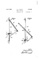
- Figure 1 is a vertical sectional view of a window of atype including a hinged sash showing the adaptation therewith of a shifting mechanism "in accordance with this inthe sash extended to open position.
- Figure 2 isa view similar to Figure 1 with the sash pivoted at its center and showing the adaptationfltherewith of a shifting mecha nism in accordancewith this invention. 7
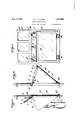
- Figure'3 is a vertical sectional view of a modified form. of widow includinga hinged sash providedwith side pieces to constitutea coal chute and showing the adaptation withthe window of a shifting mechanism in accordance with this invention and further illustrating the sash inclosed posit on.
- Figure 4 is a view similar to Figure 3 and "illustrating-the sash extended to open positionto providea coal chute ⁇
- Figure 5 is a front elevation ofthe construction shown in Figure 3.
- the shaft is journaled in a pair of spaced, combined hangers and supports to be presently referred to.
- Each combln'ed hanger and support is of substantially L-shaped; contour.
- the combined hangers and supports will be suitably designated with respect to the several figures of the drawlngs to be presentlyreferred'to.
- crank arm of the desired length and of cylindri'cal cross section. Both crank arms are illustrated in Flgure 5 and are indicated at 3, 4:. But one ofthe crank arms is shown in Figures 1, 2; 3 and 4 and in such figures, the 'crank arm is des1gnated3.
- Each crank arm at its outer end is formed with an outwardly directed, right angularly disposed extension '5providmg a combined pivot and coupler for a fiat link 7
- the links 7 have their rear ends pro vided with openings 8 throughwhich pass the extens1ons5;
- the links 7 are of'th'e de; sired length and each has its" outer end prov ded'with an opening .9 for the passage of a pivot 10.
- the pivotslO are to be carried by the sashes to be presently referred to. 7
- s 11 denotes a window frame formed wit an' Opening 12 adapted to be closed by a sash 13,
- the frame 20? provides an opening which is closed 21 mounted at its tI'ZlIlSVGIISQIIlGCllLIl upon a pivot rod 22, the latter. he ng securedto frame 20;
- Thebottom of the frame 20 is providedwith a plurality of spaced',.combined supports and;
- the upper-portion of the frame 19 provides aplurality ofopenings 27,,wh1ch are closed 'bytransparent panels28.
- the framel9 and; sash 25, as well as the'panels 28 are employed I asfacellar window.
- the frame19 is -vf0rmed with atransverse part 29 Whichcorresponds; to thesillportion 15' shown in Figure 1'.
- EjSe- I cured to the lowenface, of'tlie portion?! are the combined supportsand'han-gersjl'Z for the shaft land they are so disposed that the rear portions thereof depend downwardly,
- the shaft 1, is'mounted-in the depending portions 'of-the elements 17.
- the links 7 are pivotallyconnected: to the sash bynthepivots; 10,:
- sash 25 are rearwardly extending side mem-s 25 when, the latter is extendedte open p osi tion, provides a coal chute or a chute for conducting what is desired into the cellar,
- links 7 d are in the position shown in Figure 4"the sash 25 is latched inposition and cannot be shifted until handle 2 is swung V toward the position shown in Figure 3;
- Each link Y has one sideedgepthereo'f in 1 A hed to the sides of'the 4 7 here 30 which in connectionwiththe sash proximity to its outer end? provided with a' C cennected,
- crank arms forwardly with respect tothe frame to shift the sash to open "position and wherebyfthe crank arms wil1-reXtendiover said sill-portion so that when lowering the crank arms the sill per tion will arrest the closing movement of the sash, said handle, links and crank arms dis- I d posed rearwardly of the frame when the sash 1s closed and acting to maintain the sash in 5 closed position.
- a shiftable sash adapted to bepermanently connected to a window frame, the sill portion ofa wlndow frame, a rock shaft supported from said sill porti'on and arranged rearwardly thereof, means connected to the rock shaft and pivotally connected with the sash for shifting the latter to open and closed positions, said means coacting withflsaid'sill portion to maintain the sash in open position, and said means when the sash is in closed position arranged rearwardly of said sill portion and providing for maintaining the sash in closed position. 4:.
- a shiftable sash adapted to beconnected to a window frame capalole of being shifted towards and from the frame, the sill portion of the frame, a rock shaft supported from said sill portion rearwardly thereof, crank arms projecting from the shaft, links pivotally'connected to the sash and to the crank arms, said crank arms and-links normally positioned rearwardly of the sill portion for maintaining the sash closed, and a handle carried by the shaft and providing for the rocking thereof to project the crank arms and links forwardly with respect to said sill portion to shift the sash to open position and said crank arms, Whenthe' sash is in open position coacting witfii said sill to prevent the closure of the sas In testimony whereof, I aflix my signature hereto.
Landscapes
- Engineering & Computer Science (AREA)
- Mechanical Engineering (AREA)
- Wing Frames And Configurations (AREA)
Description
June 3, 1930. G. A. M CUEAN 1,761,392
' WINDOW CONSTRUCTION Filed Aug. 50, 1929 2 Sheets-Sheet 1 INVENTOR.
aeoryej/lf uean,
W I ATTORE.
June 3, 1930. I G, A. MCCUEAN 1,761,892
' WINDOW CONSTRUCTION Filed Aug. 50, 1929 2 Sheets-Sheet 2 f vention and .with
Patented June 3, 1930 PATENT OFFICE GEORGE A. 'McGUEAN, OF SHARPSBUBG, PENNSYLVANIA wmnow oonsrnuorron 1 Application med August so, 1929. Serial No. 389,500.
This invention relates to window construction,more'particularlyto a means for shifting a window sash to open and closed posi- 1 tions, and has forits object to provide, in a p 5 manner as hereinafter set forth, a shiftlng mechanism for expeditiously shifting'a sash to and for maintaining it in open position, as
well as for maintaining the sash in closed position when occasion requires.
Further objects of the invention are to provide, in a manneras hereinafter set forth, a window sash shifting mechanism which is simple'in its construction andarrangement, strong, durable, compact, thoroughly efiicient 15 in itsnse, conveniently operated, readily installed with respectto the sash and comparatively inexpensive to manufacture,
With the foregoing and other objectsin view theinvention consists of the novel con- 2 struct1on, comb1nat1on and arrangement of parts as hereinafter more specifically described, and illustrated in the accompanying drawings, wherein is shown an embodiment of the invention, but;it is. to be understood 1' that changes, variations and modifications can be resortedlto which fall within the scope of the-claims hereunto, appended. I
In the drawings wherein like reference characters denote, corresponding "parts throughoutthe several views V H 1 .Figure 1 is a vertical sectional view of a window of atype including a hinged sash showing the adaptation therewith of a shifting mechanism "in accordance with this inthe sash extended to open position.
Figure 2 isa view similar to Figure 1 with the sash pivoted at its center and showing the adaptationfltherewith of a shifting mecha nism in accordancewith this invention. 7
' Figure'3 is a vertical sectional view of a modified form. of widow includinga hinged sash providedwith side pieces to constitutea coal chute and showing the adaptation withthe window of a shifting mechanism in accordance with this invention and further illustrating the sash inclosed posit on.
Figure 4 is a view similar to Figure 3 and "illustrating-the sash extended to open positionto providea coal chute} Figure 5 is a front elevation ofthe construction shown in Figure 3.
shifting mechanism in accordance with thls invention and as shown in each of the views of the drawings includes a rock shaft 1 of cyl ndrical cross section; Y I 7 The shaft 1, centrally thereof, is formed with a laterally disposed handle member 2. See Figure 5. The shaft is journaled in a pair of spaced, combined hangers and supports to be presently referred to. Each combln'ed hanger and support is of substantially L-shaped; contour. The combined hangers and supports will be suitably designated with respect to the several figures of the drawlngs to be presentlyreferred'to.
The shaft 1 at each end thereof is provided with a right angularly disposed crank armof the desired length and of cylindri'cal cross section. Both crank arms are illustrated in Flgure 5 and are indicated at 3, 4:. But one ofthe crank arms is shown in Figures 1, 2; 3 and 4 and in such figures, the 'crank arm is des1gnated3. Each crank arm at its outer end is formed with an outwardly directed, right angularly disposed extension '5providmg a combined pivot and coupler for a fiat link 7 The links 7 have their rear ends pro vided with openings 8 throughwhich pass the extens1ons5; The links 7 are of'th'e de; sired length and each has its" outer end prov ded'with an opening .9 for the passage of a pivot 10. The pivotslO are to be carried by the sashes to be presently referred to. 7
Referring to Figure 1 of the drawin s 11 denotes a window frame formed wit an' Opening 12 adapted to be closed by a sash 13,
' a '12. As shown in Figure lthe link 7 is mount ed on a pivot 10 connected to sash 13 near the bottom thereof. 'It' is to be understood that a pair of links 7 and crank arms 3' will be em- 100 ployed the shifting mechanisrn shown in disposed an upward inclinationi If the handle 2' is swung to the posltion shown in Figure 1 and thatlsuchymechanism will be as shown in Figure 5, other than that the combined hangers and supports 16 will be reversely arranged with respect to the combined hangers and supports 17shown in F lgure 5. Below the sill portion .15, that part of the frame 12 whichis' nd c dat Wi l'be. .9 5
structed in the same manner as the upper p or tion of the frame 19 shown inFigure 5. V 2
With reference to Fig-M612 the frame 20? provides an opening which is closed 21 mounted at its tI'ZlIlSVGIISQIIlGCllLIl upon a pivot rod 22, the latter. he ng securedto frame 20;
c Thebottom of the frame 20 is providedwith a plurality of spaced',.combined supports and;
ang s fer-t e s a l.y: On o hich is shown and is indicated at 23; the arrangementb ingth s mea ei omb n ppcr s and hangers shown in Figure 1.
When the shaft 1- isrocked in a direction wherebyJthe-handlemember 2 thereof will project forwardly, shown in, F gures 1 and 2,} the crank arms 3 will be 'carried m a.
like directioni'to extend the links/T5 0 that the v sash 13 will be projectedto open position.
This statement also applies to the sash 21. The-weight of the sashbearing on the l nks Twill depress the crank arms 3 and as these latter engage the frame the sash 13 can-notibe closed. To close the sa$hf1310r 2O-the handle memb r 2. is w ng t the d t d lln p tion sh wninF-igures 1 and-2 and when in, suchposition the parts will. be so arranged as o p eve t he Opening of the a 1 91* 2 Un thev nd e memb r 2'is wu gv1n an;
outward'direction. The positioniof the crank ams e and ks Twh e f am '13,, r 21: i closed will he asindicatedin dotted 1 6? in Figures 1 and 2.:
Wit re er nc o. F gures san frame 19p vides an, sip isfi adap clfto, e l sed byv the sash" .25, t e l t bein hinged as at 26 ,"to-the bottom of the frame 19.
The upper-portion of the frame 19; provides aplurality ofopenings 27,,wh1ch are closed 'bytransparent panels28. The framel9 and; sash 25, as well as the'panels 28 are employed I asfacellar window. The frame19 is -vf0rmed with atransverse part 29 Whichcorresponds; to thesillportion 15' shown in Figure 1'. EjSe- I cured to the lowenface, of'tlie portion?!) are the combined supportsand'han-gersjl'Z for the shaft land they are so disposed that the rear portions thereof depend downwardly, The shaft 1, is'mounted-in the depending portions 'of-the elements 17. The links 7 are pivotallyconnected: to the sash bynthepivots; 10,:
r Whenthe-sash 25- is in closed positionthe' handle; member: 2 will be, disposed vertically and rearwardly, of; the -frame19 and the links 7 and crankqarms'31will-also be arranged ea wardly ofr' he-lframe 1.9. andrbe. I
sash; said links providedwith clearances for Figure4 the crank arms 3fand links 7 will shift the 'sa'sh 25 to the open position shown in Figure 4. sash 25 are rearwardly extending side mem-s 25 when, the latter is extendedte open p osi tion, provides a coal chute or a chute for conducting what is desired into the cellar, When' the handle memberZ- Q' and'the crank arms 3; and links 7 d are in the position shown inFigure 4"the sash 25 is latched inposition and cannot be shifted until handle 2 is swung V toward the position shown in Figure 3;
Each link Y has one sideedgepthereo'f in 1 A hed to the sides of'the 4 7 here 30 which in connectionwiththe sash proximity to its outer end? provided with a' C cennected,
invention'and'for the purpose-set forth can be readilyunderstood, and although the preferred embodiment of the invention is as f illustrated and described, yet it is to beun der'stoo'd thatchanges in the details'of construction can; be had which fall within :the
scope of the invention asiclaimed. Whatl claimri s:
1. In combination; agwindowxframe in}, 5 ns ll ortionanaa sash hinged 1 saideframejr'emotefromsaidg portion, aro'ck-= shaft supported from said sill portion and r i arranged rearwardly 'of said frame, "crank, 7 sprojectingfrom' the endsof the shaft,---
links pivotally connected toQthe. non-hinged J end of said sash pivotally "connected to said crank armsjanda handle carried by the sash and providing for the rocking of t he' same .to project the crank arms forwardly withre'spect to theframe-to'shiftjthesash to open position andwherebythe crank arms W111 extend "over "said sill -portionfso ,that
tion will arrestthe closing movement ofthe the sash when the latter is in closed position.
2. In combinatiomia window frame inrwhen lowering the crank arms the sill por i I eluding a sill portionrandfa'sashhinged to, said frame remotefromsaid portion ia rock shaft: supported from said sill portion and arranged rearwardly of said frame, crank arms prOJec'ting fromtthe. ends of'the shaft, links plvotally connected to thenon-hinged end of said sash and pivotally-connected to v said crank arms, and a handle cai'fi dl y th 5 I sash andfproviding for the rocking of: thesame to project ithe. crank arms forwardly with respect tothe frame to shift the sash to open "position and wherebyfthe crank arms wil1-reXtendiover said sill-portion so that when lowering the crank arms the sill per tion will arrest the closing movement of the sash, said handle, links and crank arms dis- I d posed rearwardly of the frame when the sash 1s closed and acting to maintain the sash in 5 closed position. r
' 3. In combination, a shiftable sash adapted to bepermanently connected to a window frame, the sill portion ofa wlndow frame, a rock shaft supported from said sill porti'on and arranged rearwardly thereof, means connected to the rock shaft and pivotally connected with the sash for shifting the latter to open and closed positions, said means coacting withflsaid'sill portion to maintain the sash in open position, and said means when the sash is in closed position arranged rearwardly of said sill portion and providing for maintaining the sash in closed position. 4:. In combination, a shiftable sash adapted to beconnected to a window frame capalole of being shifted towards and from the frame, the sill portion of the frame, a rock shaft supported from said sill portion rearwardly thereof, crank arms projecting from the shaft, links pivotally'connected to the sash and to the crank arms, said crank arms and-links normally positioned rearwardly of the sill portion for maintaining the sash closed, and a handle carried by the shaft and providing for the rocking thereof to project the crank arms and links forwardly with respect to said sill portion to shift the sash to open position and said crank arms, Whenthe' sash is in open position coacting witfii said sill to prevent the closure of the sas In testimony whereof, I aflix my signature hereto.
4o GEORGE A. MGOUEAN.
Priority Applications (1)
| Application Number | Priority Date | Filing Date | Title |
|---|---|---|---|
| US389500A US1761892A (en) | 1929-08-30 | 1929-08-30 | Window construction |
Applications Claiming Priority (1)
| Application Number | Priority Date | Filing Date | Title |
|---|---|---|---|
| US389500A US1761892A (en) | 1929-08-30 | 1929-08-30 | Window construction |
Publications (1)
| Publication Number | Publication Date |
|---|---|
| US1761892A true US1761892A (en) | 1930-06-03 |
Family
ID=23538505
Family Applications (1)
| Application Number | Title | Priority Date | Filing Date |
|---|---|---|---|
| US389500A Expired - Lifetime US1761892A (en) | 1929-08-30 | 1929-08-30 | Window construction |
Country Status (1)
| Country | Link |
|---|---|
| US (1) | US1761892A (en) |
Cited By (1)
| Publication number | Priority date | Publication date | Assignee | Title |
|---|---|---|---|---|
| US2424366A (en) * | 1944-10-18 | 1947-07-22 | Needre John | Starter and lock for fire escape panels |
-
1929
- 1929-08-30 US US389500A patent/US1761892A/en not_active Expired - Lifetime
Cited By (1)
| Publication number | Priority date | Publication date | Assignee | Title |
|---|---|---|---|---|
| US2424366A (en) * | 1944-10-18 | 1947-07-22 | Needre John | Starter and lock for fire escape panels |
Similar Documents
| Publication | Publication Date | Title |
|---|---|---|
| US1761892A (en) | Window construction | |
| US2252634A (en) | Window sash operator | |
| US2199562A (en) | Window construction | |
| US1825595A (en) | Storm sash or screen hanger | |
| US2637547A (en) | Louver window and operating mechanism | |
| US1843973A (en) | Garage, barn, and warehouse door | |
| US1600796A (en) | Casement window | |
| US1787917A (en) | Casement | |
| US1804231A (en) | Garage door | |
| US1902973A (en) | Window construction | |
| US1781864A (en) | Draft and noise stop | |
| US1661113A (en) | Hinge | |
| US1019337A (en) | Safety swinging window. | |
| US1859392A (en) | Protector for the outside baseboard of alpha window | |
| US1754623A (en) | Window-operating mechanism | |
| US920876A (en) | Window. | |
| US1743654A (en) | Device for maintaining closures in opened or closed position | |
| US607432A (en) | Hinge | |
| US722533A (en) | Window. | |
| US1352971A (en) | Balanced window | |
| US1587318A (en) | Door latch | |
| US2452119A (en) | Window frame and sash | |
| US544506A (en) | Window | |
| US1713831A (en) | Window construction | |
| US1086518A (en) | Door-check. |