US1754300A - Steam-cooling system for internal-combustion engines - Google Patents
Steam-cooling system for internal-combustion engines Download PDFInfo
- Publication number
- US1754300A US1754300A US101726A US10172626A US1754300A US 1754300 A US1754300 A US 1754300A US 101726 A US101726 A US 101726A US 10172626 A US10172626 A US 10172626A US 1754300 A US1754300 A US 1754300A
- Authority
- US
- United States
- Prior art keywords
- reservoir
- condenser
- water
- liquid
- passage
- Prior art date
- Legal status (The legal status is an assumption and is not a legal conclusion. Google has not performed a legal analysis and makes no representation as to the accuracy of the status listed.)
- Expired - Lifetime
Links
- 238000001816 cooling Methods 0.000 title description 28
- 238000002485 combustion reaction Methods 0.000 title description 27
- XLYOFNOQVPJJNP-UHFFFAOYSA-N water Substances O XLYOFNOQVPJJNP-UHFFFAOYSA-N 0.000 description 86
- 239000007788 liquid Substances 0.000 description 64
- 238000009833 condensation Methods 0.000 description 11
- 230000005494 condensation Effects 0.000 description 11
- 238000010992 reflux Methods 0.000 description 11
- 239000002826 coolant Substances 0.000 description 6
- POIUWJQBRNEFGX-XAMSXPGMSA-N cathelicidin Chemical compound C([C@@H](C(=O)N[C@@H](CCCNC(N)=N)C(=O)N[C@@H](CCCCN)C(=O)N[C@@H](CO)C(=O)N[C@@H](CCCCN)C(=O)N[C@@H](CCC(O)=O)C(=O)N[C@@H](CCCCN)C(=O)N[C@@H]([C@@H](C)CC)C(=O)NCC(=O)N[C@@H](CCCCN)C(=O)N[C@@H](CCC(O)=O)C(=O)N[C@@H](CC=1C=CC=CC=1)C(=O)N[C@@H](CCCCN)C(=O)N[C@@H](CCCNC(N)=N)C(=O)N[C@@H]([C@@H](C)CC)C(=O)N[C@@H](C(C)C)C(=O)N[C@@H](CCC(N)=O)C(=O)N[C@@H](CCCNC(N)=N)C(=O)N[C@@H]([C@@H](C)CC)C(=O)N[C@@H](CCCCN)C(=O)N[C@@H](CC(O)=O)C(=O)N[C@@H](CC=1C=CC=CC=1)C(=O)N[C@@H](CC(C)C)C(=O)N[C@@H](CCCNC(N)=N)C(=O)N[C@@H](CC(N)=O)C(=O)N[C@@H](CC(C)C)C(=O)N[C@@H](C(C)C)C(=O)N1[C@@H](CCC1)C(=O)N[C@@H](CCCNC(N)=N)C(=O)N[C@@H]([C@@H](C)O)C(=O)N[C@@H](CCC(O)=O)C(=O)N[C@@H](CO)C(O)=O)NC(=O)[C@H](CC=1C=CC=CC=1)NC(=O)[C@H](CC(O)=O)NC(=O)CNC(=O)[C@H](CC(C)C)NC(=O)[C@@H](N)CC(C)C)C1=CC=CC=C1 POIUWJQBRNEFGX-XAMSXPGMSA-N 0.000 description 2
- 108010057108 condensin complexes Proteins 0.000 description 2
- 238000010276 construction Methods 0.000 description 2
- 238000001704 evaporation Methods 0.000 description 2
- 230000008020 evaporation Effects 0.000 description 2
- 230000005484 gravity Effects 0.000 description 2
- 102000004726 Connectin Human genes 0.000 description 1
- 108010002947 Connectin Proteins 0.000 description 1
- 230000015572 biosynthetic process Effects 0.000 description 1
- 238000009835 boiling Methods 0.000 description 1
- 239000000110 cooling liquid Substances 0.000 description 1
- 238000004326 stimulated echo acquisition mode for imaging Methods 0.000 description 1
Images
Classifications
-
- F—MECHANICAL ENGINEERING; LIGHTING; HEATING; WEAPONS; BLASTING
- F01—MACHINES OR ENGINES IN GENERAL; ENGINE PLANTS IN GENERAL; STEAM ENGINES
- F01P—COOLING OF MACHINES OR ENGINES IN GENERAL; COOLING OF INTERNAL-COMBUSTION ENGINES
- F01P3/00—Liquid cooling
- F01P3/22—Liquid cooling characterised by evaporation and condensation of coolant in closed cycles; characterised by the coolant reaching higher temperatures than normal atmospheric boiling-point
- F01P3/2271—Closed cycles with separator and liquid return
Definitions
- the object of our invention is to provide a novel steam cooling system for internal combustion engines, especially automobile engines, taining and thereafter maintaining the engine cooling medium at a high temperature in the engine water jacket for ensuring the most eflicient and economical operation of the engine.
- the system includes a water jacket, a condenser, a reservoir and two circuits, one passing through the water jacket and reservoir and the other passing through the reservoir and condenser, means being provided in the last named circuit for returning the water of condensation to the reservoir, said means in the present instance being shown as a pump driven from the engine.
- the engine water jacket is denoted by 1, the top of which forms a steam space.
- the condenser may be of any well known or approved construction.
- a condenser comprising juxtaposed direct and reflux condensing units.
- the passages 2 of the direct condensing unit connect the upper and lower chamhere 4 and 5 and the passages 3 of the reflux condensing unit connect the upper and lower chambers 6 and 7.
- the lower chamber 7 ma be provided with an overflow passage 8.
- valved passage 9 leads from the lower chamber 5 of the direct condensing unit to the lower chamber 7 of the reflux condensing unit.
- passages 2 and 3 of the two condensing units may be of any well known or approved form.
- the reservoir for the cooling medium is denoted by 10.
- a water supply passage 11 leads from the bottom of the reservoir 10 to the bottom of the water jacket 1.
- a valve 12 is provided in this passage 11 for preventing the steam pressure in the water jac ret returning the water to the reservoir.
- a steam passage 13 leads from the top of the water jacket 1 into the reservoir 10 at a point above its normal water level.
- a steam passage 14 leads from the reservoir 10 into the upper chamber which system is capable of quickly ob- 1926. Serial No. 101,726.
- the reservoir mouth of the said passage 14 being preferably located beow the reservoir mouth of the steam passa e 13.
- Means are provided for returning the Water of condensation from the condenser to the reservoir, which means is herein shown as a passage 15 leading from the lower chamber 7 of the reflux condensing unit through an engine driven pump 16 to the reservoir 10 at. it pcl int preferably above its normal water eve
- the reservoir 10 may be provided with e fillin cap 17 and the condenser may be provided with a filling cap 18 for the upper chamber 6 of the reflux condensing unit 3'.
- the water supply passage 11 may be provided with a drain cock 19, the pump 16'with a drain cook 20, the lower chamber 5 of the direct condensing unit with a draincock 21 and the lower chamber 7 of the reflux c'ondensing unit with a drain cook 22.
- the top of the water jacket 1 maybe provided with a two-way safety valve denoted conventionally by 23, operable in case of a possible stoppage in any of the passages.
- the upper chamber 6 of the reflux condensing unit 3 is provided with a vent 23* to external atmosphere.
- the filling plug 17 is removed and the water is poured into the reservoir 10.
- the water will first fill the water jacket 1, then the reservoir 10 to the passage 14 and then the direct and reflux condensing units of the condenser to the level of the discharge end of the overflow passage 8, thus filling the lower chambers 5 and 7 and partly filling the passages 2 and 3.
- the filling plug 17 is then replaced. Thereafter when it becomes necessary to add water to take the place of any loss by leakage or evaporation, the water may be supplied by removing the filling cap 18 for the upper chamber 6 of the reflux condensing unit.
- the uncondensed portion of the steam passes on through the passage 14 into the upper chamber 4 of the direct condensing unit where it is condensed and joins the water in the lower chamber 5 of said unit.
- the pressures in the water jacket and in the reservoir will be nearly equal so that as the steam is lost from the water jacket, water from the reservoir 10 will flow through the passage 11 into the water jacket to take its place.
- the valve 12 prevents the return of the water from the water jacket in case of a sudden formation of steam therein. Also the valve in the passage 9 between the lower chambers 5 and 7 of the condenser will prevent the sucking of the water up into the reservoir if much steam is suddenly condensed in the reservoir.
- the air is normally supplied to the system through the vent 23* and overflow passage 8. If any of the passages should become stopped, the two-way safety valve 23 in the top of the water jacket w1ll act.
- a water jacket, a condenser, a reservoir passages between the reservoir and the tops of the jacket and condenser respectively, passages between the reservoir and jacket and between the reservoir and bottom of the condenser, and means located in the passage connecting the reservoir with the bot tom of the condenser for lifting the water of condensation from the bottom of the condenser into the reservoir, the reservoir mouth of the assage from the bottom of the condenser eing located above the normal water level in the reservoir.
- a reservoir passages between the reservoir and the tops of the jacket and condenser respectively, passages between the reservoir and jacket and between the reservoir and bottom of the condenser, and means located in the passa e connecting the reservoir with the bottom 0 the condenser for lifting the water of condensation from the bottom of the condenser into the reservoir,the reservoir mouth of the passage from the jacket being located at a higher level than the reservoir mouth of the passage to the top of the condenser, the reservoir mouth of the passage from the bottom of the condenser being located above the normal water level in the reservoir.
- a water jacket for internal combus tion engines, a water jacket, a condenser, a reservoir, a water supply passage leading from the reservoir to the jacket, a steam escape passage leading from the jacket to the reservoir above its water level, a steam escape passage leading from the reservoir above its water level to the top of the condenser, a return passage leading from the bottom of the condenser to the reservoir above its water level, and means for lifting the water of condensation through said return passage into the reservoir before it passes into the water jacket.
- a cooling system for internal combustion engines a water jacket, a condenser, two. circuits, a reservoir common to the two circuits, one circuit including passages for bringing the reservoir into commumcation with the water jacket at different levels and the other circuit including passages for bringing the reservoir into communication with the top and bottom of the condenser, and means arranged to lift the water of condensation from the bottom of the condenser into the reservoir before it passes into the water jacket.
- a water jacket a condenser, two circuits, a reservoir common to the two circuits, one of said circuits includin a steam passage leading from the top of the water acket to the reservoir and a water passage leading from the reservoir to the water jacket, and the other circuit including a steam passage leading from the reservoir to the to of the condenser and a water passage lea ing from the bottom of the condenser to the reservoir, and means located in the last named water'passage for lifting the water of condensation from the bottom of the condenser into the reservoir before it passes into the Water jacket.
- a water jacket In a cooling system for internal combustion engines, a water jacket, a condenser, two circuits, a reservoir common to the two circuits, one of said circuits including a steam passage leading from the top of the water jacket to the reservoir and a watery passage leading from the reservoir to the water jacket, and the other circuit including a steam passage leading from the reservoir to the top of the condenser and a water passage leading from the bottom of the condenser to the reservoir, and a pump located in the last named water passage for lifting the water of condensation from the bottom of the condenser into the reservoir before it passes into the water jacket.
- a cooling system for internal combustion engines a water jacket, a condenser, two circuits, a reservoir common to the two circuits, one of said circuits including a steam passage leading from the top of the water jacket to the reservoir and a water passage eadin from the reservoir to the water jacket, and the other circuit including a steam passage leading from the reservoir to the top of the condenser and a water passage leading from the bottom of the condenser to the reservoir, the reservoir mouth of the steam passage from the to of the water jacket being located at a big er level than the reservoir mouth of the steam passage leading to the top of the condenser, and means located in the last named water passage for lifting the water of condensation from the bottom of the condenser into the reservoir before it passes into the water jacket.
- An arrangement for cooling internal combustion engines by eve oration comprising a main circuit for the iquid' cooling medium, an evaporator in said circuit, an auxiliary circuit including a condenser for condensing the vapor separated from said liquid, said condenser communicatin at one end with the evaporator above the liquid therein, and communicatin atits other end with the atmosphere and t e upper portion of the evaporator.
- An arrangement for cooling internal combustion engines b evaporation comprising a main circuit or theliquid cooling medium, an evaporator in said circuit, an auxiliary circuit including a condenser for condensing the vapor separated from said liquid, said condenser communicating at one end with the evaporator above the liquid therein, and communicating at its other end with the atmosphere and the upper portion of the evaporator, and a pump in the auxiliary circuit for returning the condensate from the condenser to the evaporator above the liquid in the latter.
- a liquid reservoir in intercommunication, said condenser having upper and lower chambers and their connecting condensing passages, and means including a reservoir liquid overflow outlet leadin to the upper condenser chamber for maintaming the liquid in the reservoir at a predetermined level.
- a iquid reservoir in communication therewith, said condenser having upper and lower chambers and their connecting condensing passages, a cylinder jacket in communication with the reservoir and condenser, and means for maintaining the liquid at a predetermined level in the reservoir including a reservoir liquid overflow outlet leading to the upper condenser chamber.
- a liquid reservoir in communication therewith, said condenser having upper and lower chambers and their connecting condensing passages, a cylinder jacket in communication with the reservoir and condenser, and means for maintaining the cooling liquid at a predetermined level in the reservoir including a reservoir liquid overflow outlet leading to the upper condenser, chamber, and means for raising the overflow and condensed liquid back into the reservoir.
- a liquid reservoir a condenser and a cylinder jacket
- said condenser having upper and lower chambers and their connectin condensin passa es
- the reservoir having a iquid over ow out at leading to the upper condenser chamber and a liquid supply outlet in communication with the cylinder acket
- the cylinder jacket having a vapor outlet in communication with the condenser and the condenser having a liquid outlet in communication with the reservoir, and means for replenishing the liquid supply in the reservoir.
- a liquid reservoir 9. condenser and a cylinder jacket, the reservoir having a liquid overflow outlet in communication with the condenser and a liquid supply outlet in communication with the cylinder jacket, the cylinder jacket having a vapor outlet in communication with the condenser and the condenser having a liquid outlet in communication with the reservoir, and means for replenishing the liquid supply in the reservoir, the said reservoir and its overflow outlet being so located with respect to the cylinder jacket as to prevent the passa e of liquid from the cylinder jacket through its vapor outlet.
- a liquid reservoir for internal combustion engines, a liquid reservoir, a condenser and a cylinder jacket, said condenser having upper and lower connecting condensing passages, the reservoir having a liquid return passage leading from the condenser, a liquid overflow passage leading to the upper condenser chamber and a liquid supply passage leadin to the cylinder jacket, the cylinder jacket aving a vapor escape passage leading to the condenser, and means for replenishing the li uid supply in the reservoir.
- acoollng system for internal combustion engines a liquid reservoir, a condenser and a cylinder acket, the reservoir having a liquid return assage leading from the condenser, a liquid overflow passage communicating with the condenser and a liquid supply passage leading to the cylinder jacket, the cylinder jacket havin a vapor escape passage leading to the con enser, and means for replenishing the liquid supply in the reservoir, the said reservoir and its overflow passa e being so located with respect to the cyllnder jacket as to prevent the passage of liquid from the cylinder jacket through its vapor escape passage, to the condenser.
- a liquid reservoir a condenser and a cylinder jacket
- a liquid return passage leading from the condenser to the reservoir
- a va or escape passage leading from the cylin er jacket to the condenser
- a cooling s stem for internal combustion en ines, a liquid reservoir, a condenser an a cylinder jacket in intercommunication, means for replenishing the liquid supply in the reservoir, and means for maintaining the liquid at a predetermined level in the reservoir whereby the liquid will, by the action of gravity, be maintained at a out a predetermined level in the cylinder jacket under normal operating conditions, said means including a cylinder jacket, a liquid supply passage eading from the bottom of the reservoir and a reservoir liquid overflow passage located at a predetermined height above the bottom of the reservoir.
- a cooling s stem for internal combustion engines a iquid reservoir, a condenser and a cylinder 'acket in intercommunication, the cylinder acket having a vapor escape passage leading to the condenser, and the reservoir having a liquid supply passage leading to the cylinder jacket, a liquid overflow passage leading from the reservoir and a liquid return passage, and means in the last named passage for raising the overflow and condensed liquid back into the reservoir, whereby the liquid in the reservoir may be maintained at a predetermined level to thereby cause the liquid in the cylinder jacket to be maintained by gravit at substantially a predetermined level un er normal operating conditions.
- a liquid reservoir, a condenser and a cylinder jacket in intercommunication having a vapor escape passage leading to the condenser
- the reservoir having a liquid supply passage leading to the cylinder jacket, a liquid overflow passage leading from the reservoir to the condenser and a liquid return passage leading from the condenser, and means in the last named passage for raising the overflow and condensed liquid back into the reservoir whereby the liquid in the reservoir may be maintained at a predetermined level to thereby cause the liqpid in the cylinder jacket to be maintained y gravity at substantially a predetermined level under normal operating conditions.
- a liquid reservoir In a cooling system for internal combustionv engines, a liquid reservoir,.a con denser and a cylinder jacket in intercommunication, the'cylinder jacket having a vapor esca e passage in communication with the con enser, and the reservoir having a liquid overflow outlet, the said reservoir and its overflow outlet being so located with respect to the cylinder jacket as to prevent the circulation of liquid through the cylinder jacket.
- a liquid reservoir, a con-' denser and a cylinder jacket in intercommunication the cylinder jacket having a vapor escape passage, the outlet of which is in communication with the condenser, and the reservoir having a liquid overflow outlet located below the vapor escape passage outlet, the said reservoir and its overflow out-let being so located with respect to the cylinder jacket as to prevent the circulation of liquid through the cylinder jacket.
Landscapes
- Engineering & Computer Science (AREA)
- Chemical & Material Sciences (AREA)
- Combustion & Propulsion (AREA)
- Mechanical Engineering (AREA)
- General Engineering & Computer Science (AREA)
- Engine Equipment That Uses Special Cycles (AREA)
Description
April 15, 1930. H, AYRES ET AL 1,754,300
STEAM COOLING SYSTEM FOR INTERNAL COMBUSTION ENGINES Filed April 15, 1926 A INVENTORS f/s/v 7/ wm Mr fi- ATTORN EYS Patented Apr. 15, 1930 UNITED STATES PATENT OFFICE ma HUBEBT exams, on NEW YORK, 1v. Y., annnnnnnm: mmmn mum, on
- nsiman'nsvxnnn, new JERSEY STEAM-COOLING SYSTEM FOR INTERNAL-COMBUSTION ENGINES Appllcation'flled April 18,
- The object of our invention is to provide a novel steam cooling system for internal combustion engines, especially automobile engines, taining and thereafter maintaining the engine cooling medium at a high temperature in the engine water jacket for ensuring the most eflicient and economical operation of the engine. The system includes a water jacket, a condenser, a reservoir and two circuits, one passing through the water jacket and reservoir and the other passing through the reservoir and condenser, means being provided in the last named circuit for returning the water of condensation to the reservoir, said means in the present instance being shown as a pump driven from the engine.
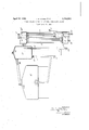
A practical embodiment of our invention is 'represented in the accompanying drawing which illustrates the system partly in side elevation and partly in section.
The engine water jacket is denoted by 1, the top of which forms a steam space.
The condenser may be of any well known or approved construction. In the present instance we have shown a condenser comprising juxtaposed direct and reflux condensing units. The passages 2 of the direct condensing unit connect the upper and lower chamhere 4 and 5 and the passages 3 of the reflux condensing unit connect the upper and lower chambers 6 and 7. The lower chamber 7 ma be provided with an overflow passage 8. valved passage 9 leads from the lower chamber 5 of the direct condensing unit to the lower chamber 7 of the reflux condensing unit.
It will be understood that the passages 2 and 3 of the two condensing units may be of any well known or approved form.
The reservoir for the cooling medium is denoted by 10. A water supply passage 11 leads from the bottom of the reservoir 10 to the bottom of the water jacket 1. A valve 12 is provided in this passage 11 for preventing the steam pressure in the water jac ret returning the water to the reservoir. A steam passage 13 leads from the top of the water jacket 1 into the reservoir 10 at a point above its normal water level. A steam passage 14 leads from the reservoir 10 into the upper chamber which system is capable of quickly ob- 1926. Serial No. 101,726.
4 of the direct condensing unit 2 the condenser at a point above the normal water level in the reservoir, the reservoir mouth of the said passage 14 being preferably located beow the reservoir mouth of the steam passa e 13.
Means are provided for returning the Water of condensation from the condenser to the reservoir, which means is herein shown as a passage 15 leading from the lower chamber 7 of the reflux condensing unit through an engine driven pump 16 to the reservoir 10 at. it pcl int preferably above its normal water eve The reservoir 10 may be provided with e fillin cap 17 and the condenser may be provided with a filling cap 18 for the upper chamber 6 of the reflux condensing unit 3'.
The water supply passage 11 may be provided with a drain cock 19, the pump 16'with a drain cook 20, the lower chamber 5 of the direct condensing unit with a draincock 21 and the lower chamber 7 of the reflux c'ondensing unit with a drain cook 22. The top of the water jacket 1 maybe provided with a two-way safety valve denoted conventionally by 23, operable in case of a possible stoppage in any of the passages. The upper chamber 6 of the reflux condensing unit 3 is provided with a vent 23* to external atmosphere.
To put the system in operative condition,
the filling plug 17 is removed and the water is poured into the reservoir 10. The water will first fill the water jacket 1, then the reservoir 10 to the passage 14 and then the direct and reflux condensing units of the condenser to the level of the discharge end of the overflow passage 8, thus filling the lower chambers 5 and 7 and partly filling the passages 2 and 3. The filling plug 17 is then replaced. Thereafter when it becomes necessary to add water to take the place of any loss by leakage or evaporation, the water may be supplied by removing the filling cap 18 for the upper chamber 6 of the reflux condensing unit.
In operation :-When the engine is started, the pump 16, driven by the water from the chamber 7 through one branch of the passage 15 and force it up through the other branch of the passage into the engine, will take l the reservoir 10. It will be seen that this water does not circulate through the water jacket 1 but passes through the passage 14 into the upper chamber- 4 and downwardly through the passa es 2 into the lower chamber 5, and from thence through the valved assage 9 into the lower chamber 7. There lieing no circulation of water through the water jacket 1, the water in the water jacket will become rapidly heated to the boiling point, the steam passing from the top of the water jacket through the passage 13 into the reservoir 10 where some of it is condensed. The uncondensed portion of the steam passes on through the passage 14 into the upper chamber 4 of the direct condensing unit where it is condensed and joins the water in the lower chamber 5 of said unit. As the water jacket 1 and reservoir 10 are directly connected through the passage 13, the pressures in the water jacket and in the reservoir will be nearly equal so that as the steam is lost from the water jacket, water from the reservoir 10 will flow through the passage 11 into the water jacket to take its place. The valve 12 prevents the return of the water from the water jacket in case of a sudden formation of steam therein. Also the valve in the passage 9 between the lower chambers 5 and 7 of the condenser will prevent the sucking of the water up into the reservoir if much steam is suddenly condensed in the reservoir.
Should the engine be working under unusual conditions of load or temperature and generating more steam in the water jacket than can be condensed in the direct condensing unit, the excess steam will pass upwardly into the lower chamber 7 through the water therein which will assist in the condensation of the steam) and rise throu h the passages 3 into the upper chamber 6 0% the reflux condensin unit until it escapes through the vent 23". owever, the greatest practicable quantity of the steam will be condensed in the reflux condensing unit which is placed in front of the direct condensing unit in the coldest part of the system and the condensed steam will fall into the lower chamber 7.
The air is normally supplied to the system through the vent 23* and overflow passage 8. If any of the passages should become stopped, the two-way safety valve 23 in the top of the water jacket w1ll act.
From the above description it will be seen that two separate circuits are provided in the cooling system, one circuit passing through the reservoir 10 and water acket 1 and the other circuit passing through the reservoir 10, the condenser, and the pump 16.
While describing this cooling system in connection with water as a'cooling medium, it is to be understood that any suitable liquid may be utilized as the cooling medium.
The condenser shown and described, but not claimed herein, forms'the subject matter of our copending application, filed'of even date herewith, its Serial Number being 101,724.
It is evident that various changes ma be resorted to in the construction, form an arrangement of the several parts without departing from the spirit and scope of our invention; hence we do not intendto be limited to theparticular embodiment herein shown and described, but
What we claim is 1. In a cooling system for internal combustion engines, a water jacket, a condenser, a reservoir, two circuits, one through the jacket and reservoir and the other through the reservoir and condenser, and means in the last named circuit for lifting the water of condensation from the bottom of the con-- denser into the reservoir.
2. In a cooling system for internal combustion engines, a water jacket, a condenser, a reservoir, passages between the reservoir and the tops of the jacket and condenser respectively, passages between the reservoir and jacket and between the reservoir and bottom of the condenser, and means located in the passage connecting the reservoir with the bot tom of the condenser for lifting the water of condensation from the bottom of the condenser into the reservoir, the reservoir mouth of the assage from the bottom of the condenser eing located above the normal water level in the reservoir.
3. In a cooling system for internal combustion engines, a water jacket, a condenser,
a reservoir, passages between the reservoir and the tops of the jacket and condenser respectively, passages between the reservoir and jacket and between the reservoir and bottom of the condenser, and means located in the passa e connecting the reservoir with the bottom 0 the condenser for lifting the water of condensation from the bottom of the condenser into the reservoir,the reservoir mouth of the passage from the jacket being located at a higher level than the reservoir mouth of the passage to the top of the condenser, the reservoir mouth of the passage from the bottom of the condenser being located above the normal water level in the reservoir.
4. In a cooling system for internal combus tion engines, a water jacket, a condenser, a reservoir, a water supply passage leading from the reservoir to the jacket, a steam escape passage leading from the jacket to the reservoir above its water level, a steam escape passage leading from the reservoir above its water level to the top of the condenser, a return passage leading from the bottom of the condenser to the reservoir above its water level, and means for lifting the water of condensation through said return passage into the reservoir before it passes into the water jacket.
5. In a cooling system for internal combustion engines, a water jacket, a condenser, two. circuits, a reservoir common to the two circuits, one circuit including passages for bringing the reservoir into commumcation with the water jacket at different levels and the other circuit including passages for bringing the reservoir into communication with the top and bottom of the condenser, and means arranged to lift the water of condensation from the bottom of the condenser into the reservoir before it passes into the water jacket. a
6. In a cooling system for internal combustion engines, a water jacket, a condenser, two circuits,a reservoir common to the two circuits, one of said circuits includin a steam passage leading from the top of the water acket to the reservoir and a water passage leading from the reservoir to the water jacket, and the other circuit including a steam passage leading from the reservoir to the to of the condenser and a water passage lea ing from the bottom of the condenser to the reservoir, and means located in the last named water'passage for lifting the water of condensation from the bottom of the condenser into the reservoir before it passes into the Water jacket.
7'. In a cooling system for internal combustion engines, a water jacket, a condenser, two circuits, a reservoir common to the two circuits, one of said circuits including a steam passage leading from the top of the water jacket to the reservoir and a watery passage leading from the reservoir to the water jacket, and the other circuit including a steam passage leading from the reservoir to the top of the condenser and a water passage leading from the bottom of the condenser to the reservoir, and a pump located in the last named water passage for lifting the water of condensation from the bottom of the condenser into the reservoir before it passes into the water jacket.
8. In a cooling system for internal combustion engines, a water jacket, a condenser, two circuits, a reservoir common to the two circuits, one of said circuits including a steam passage leading from the top of the water jacket to the reservoir and a water passage eadin from the reservoir to the water jacket, and the other circuit including a steam passage leading from the reservoir to the top of the condenser and a water passage leading from the bottom of the condenser to the reservoir, the reservoir mouth of the steam passage from the to of the water jacket being located at a big er level than the reservoir mouth of the steam passage leading to the top of the condenser, and means located in the last named water passage for lifting the water of condensation from the bottom of the condenser into the reservoir before it passes into the water jacket.
9. An arrangement for cooling internal combustion engines by eve ing a main circuit for the li circuit for the vaporized ration, compris medium separate from said liquid, and auxliary circuit including a. condenser in permanent communication with a pressure gas through an opening arranged at a point in the condenser out of reach of the vapors, and means to return the condensate from the condenser to the main circuit.
' 10. An arrangement for cooling internal combustion engines by eve oration, comprising a main circuit for the iquid' cooling medium, an evaporator in said circuit, an auxiliary circuit including a condenser for condensing the vapor separated from said liquid, said condenser communicatin at one end with the evaporator above the liquid therein, and communicatin atits other end with the atmosphere and t e upper portion of the evaporator.
11. An arrangement for cooling internal combustion engines b evaporation, comprising a main circuit or theliquid cooling medium, an evaporator in said circuit, an auxiliary circuit including a condenser for condensing the vapor separated from said liquid, said condenser communicating at one end with the evaporator above the liquid therein, and communicating at its other end with the atmosphere and the upper portion of the evaporator, and a pump in the auxiliary circuit for returning the condensate from the condenser to the evaporator above the liquid in the latter.
12. In a cooling system for internal combustion engines, a liquid reservoir, a condenser and a cylinder jacket in intercommunication, said condenser having upper and lower chambers and their connecting condensing passages, and means including a reservoir liquid overflow outlet leadin to the upper condenser chamber for maintaming the liquid in the reservoir at a predetermined level.
13. In a coolin system for internal combustion engines, a iquid reservoir, a condenser in communication therewith, said condenser having upper and lower chambers and their connecting condensing passages, a cylinder jacket in communication with the reservoir and condenser, and means for maintaining the liquid at a predetermined level in the reservoir including a reservoir liquid overflow outlet leading to the upper condenser chamber.
14. In a cooling system for internal combustion engines, a liquid reservoir, a condenser in communication therewith, said condenser having upper and lower chambers and their connecting condensing passages, a cylinder jacket in communication with the reservoir and condenser, and means for maintaining the cooling liquid at a predetermined level in the reservoir including a reservoir liquid overflow outlet leading to the upper condenser, chamber, and means for raising the overflow and condensed liquid back into the reservoir. v p
15. In a cooling system for internal combustion engines, a liquid reservoir, a condenser and a cylinder jacket, said condenser having upper and lower chambers and their connectin condensin passa es, the reservoir having a iquid over ow out at leading to the upper condenser chamber and a liquid supply outlet in communication with the cylinder acket, the cylinder jacket having a vapor outlet in communication with the condenser and the condenser having a liquid outlet in communication with the reservoir, and means for replenishing the liquid supply in the reservoir.
16. In a cooling system for internal combustion engines, a liquid reservoir, 9. condenser and a cylinder jacket, the reservoir having a liquid overflow outlet in communication with the condenser and a liquid supply outlet in communication with the cylinder jacket, the cylinder jacket having a vapor outlet in communication with the condenser and the condenser having a liquid outlet in communication with the reservoir, and means for replenishing the liquid supply in the reservoir, the said reservoir and its overflow outlet being so located with respect to the cylinder jacket as to prevent the passa e of liquid from the cylinder jacket through its vapor outlet.
17. In a cooling system for internal combustion engines, a liquid reservoir, a condenser and a cylinder jacket, said condenser having upper and lower connecting condensing passages, the reservoir having a liquid return passage leading from the condenser, a liquid overflow passage leading to the upper condenser chamber and a liquid supply passage leadin to the cylinder jacket, the cylinder jacket aving a vapor escape passage leading to the condenser, and means for replenishing the li uid supply in the reservoir.
18. n acoollng system for internal combustion engines, a liquid reservoir, a condenser and a cylinder acket, the reservoir having a liquid return assage leading from the condenser, a liquid overflow passage communicating with the condenser and a liquid supply passage leading to the cylinder jacket, the cylinder jacket havin a vapor escape passage leading to the con enser, and means for replenishing the liquid supply in the reservoir, the said reservoir and its overflow passa e being so located with respect to the cyllnder jacket as to prevent the passage of liquid from the cylinder jacket through its vapor escape passage, to the condenser.
19. In a cooling system for internal combustion engines, a liquid reservoir, a condenser and a cylinder jacket, a liquid return passage leading from the condenser to the reservoir, a va or escape passage leading from the cylin er jacket to the condenser,
a liquid supply passage leading from the bottom of the reservoir to the cylinder jacket, a liquid overflow. assage bringing the reservoir into communication with the condenser, and means for raising the liquid into the reservoir through the first named passage.
20. In a cooling s stem for internal combustion en ines, a liquid reservoir, a condenser an a cylinder jacket in intercommunication, means for replenishing the liquid supply in the reservoir, and means for maintaining the liquid at a predetermined level in the reservoir whereby the liquid will, by the action of gravity, be maintained at a out a predetermined level in the cylinder jacket under normal operating conditions, said means including a cylinder jacket, a liquid supply passage eading from the bottom of the reservoir and a reservoir liquid overflow passage located at a predetermined height above the bottom of the reservoir.
21. In a cooling s stem for internal combustion engines, a iquid reservoir, a condenser and a cylinder 'acket in intercommunication, the cylinder acket having a vapor escape passage leading to the condenser, and the reservoir having a liquid supply passage leading to the cylinder jacket, a liquid overflow passage leading from the reservoir and a liquid return passage, and means in the last named passage for raising the overflow and condensed liquid back into the reservoir, whereby the liquid in the reservoir may be maintained at a predetermined level to thereby cause the liquid in the cylinder jacket to be maintained by gravit at substantially a predetermined level un er normal operating conditions.
22. In a cooling system for internal combustion engines, a liquid reservoir, a condenser and a cylinder jacket in intercommunication, the cylinder jacket having a vapor escape passage leading to the condenser, and the reservoir having a liquid supply passage leading to the cylinder jacket, a liquid overflow passage leading from the reservoir to the condenser and a liquid return passage leading from the condenser, and means in the last named passage for raising the overflow and condensed liquid back into the reservoir whereby the liquid in the reservoir may be maintained at a predetermined level to thereby cause the liqpid in the cylinder jacket to be maintained y gravity at substantially a predetermined level under normal operating conditions.
23. In a cooling system for internal combustionv engines, a liquid reservoir,.a con denser and a cylinder jacket in intercommunication, the'cylinder jacket having a vapor esca e passage in communication with the con enser, and the reservoir having a liquid overflow outlet, the said reservoir and its overflow outlet being so located with respect to the cylinder jacket as to prevent the circulation of liquid through the cylinder jacket.
24. In a cooling system for internal combustion engines, a liquid reservoir, a con-' denser and a cylinder jacket in intercommunication, the cylinder jacket havinga vapor escape passage, the outlet of which is in communication with the condenser, and the reservoir having a liquid overflow outlet located below the vapor escape passage outlet, the said reservoir and its overflow out-let being so located with respect to the cylinder jacket as to prevent the circulation of liquid through the cylinder jacket.
In testimony, that we claim the foregoing as our joint invention, we have signed our names this 30th day of March, 1926.
IRA HUBERT AYRES. HERBERT RIVINGTON PYNE.
Priority Applications (1)
| Application Number | Priority Date | Filing Date | Title |
|---|---|---|---|
| US101726A US1754300A (en) | 1926-04-13 | 1926-04-13 | Steam-cooling system for internal-combustion engines |
Applications Claiming Priority (1)
| Application Number | Priority Date | Filing Date | Title |
|---|---|---|---|
| US101726A US1754300A (en) | 1926-04-13 | 1926-04-13 | Steam-cooling system for internal-combustion engines |
Publications (1)
| Publication Number | Publication Date |
|---|---|
| US1754300A true US1754300A (en) | 1930-04-15 |
Family
ID=22286078
Family Applications (1)
| Application Number | Title | Priority Date | Filing Date |
|---|---|---|---|
| US101726A Expired - Lifetime US1754300A (en) | 1926-04-13 | 1926-04-13 | Steam-cooling system for internal-combustion engines |
Country Status (1)
| Country | Link |
|---|---|
| US (1) | US1754300A (en) |
Cited By (1)
| Publication number | Priority date | Publication date | Assignee | Title |
|---|---|---|---|---|
| US4367699A (en) * | 1981-01-27 | 1983-01-11 | Evc Associates Limited Partnership | Boiling liquid engine cooling system |
-
1926
- 1926-04-13 US US101726A patent/US1754300A/en not_active Expired - Lifetime
Cited By (1)
| Publication number | Priority date | Publication date | Assignee | Title |
|---|---|---|---|---|
| US4367699A (en) * | 1981-01-27 | 1983-01-11 | Evc Associates Limited Partnership | Boiling liquid engine cooling system |
Similar Documents
| Publication | Publication Date | Title |
|---|---|---|
| US2086441A (en) | Cooling system for internal combustion engines | |
| US1754300A (en) | Steam-cooling system for internal-combustion engines | |
| US1338722A (en) | Cooling apparatus for internal-combustion engines | |
| US2825317A (en) | Steam separator | |
| US2403218A (en) | Cooling system for internalcombustion engines | |
| US1687679A (en) | Engine-cooling system | |
| US1311529A (en) | Cooling system | |
| US1700270A (en) | Process of and means for cooling internal-combustion engines | |
| US1694518A (en) | Engine-lubricating system | |
| US1710268A (en) | Cooling system for internal-combustion engines | |
| US1630068A (en) | Cooling system | |
| US1480280A (en) | malloby | |
| US1632583A (en) | Engine-cooling system | |
| US1634844A (en) | Cooling system for internal-combustion engines | |
| US1632596A (en) | Vapor-cooling system | |
| US1838450A (en) | Cooling system | |
| US1632582A (en) | Engine-cooling system | |
| US1337576A (en) | Radiatob | |
| US1646070A (en) | Circulating system for internal-combustion engines | |
| US1706693A (en) | Internal-combustion engine | |
| US1754301A (en) | Cooling system for internal-combustion engines | |
| US1651157A (en) | Cooling system | |
| US1632581A (en) | Engine-cooling system | |
| US1643511A (en) | Cooling system for internal-combustion engines and method of operating the same | |
| US1671440A (en) | Means for operating internal-combustion engines |