US1753692A - Heel - Google Patents
Heel Download PDFInfo
- Publication number
- US1753692A US1753692A US263072A US26307228A US1753692A US 1753692 A US1753692 A US 1753692A US 263072 A US263072 A US 263072A US 26307228 A US26307228 A US 26307228A US 1753692 A US1753692 A US 1753692A
- Authority
- US
- United States
- Prior art keywords
- heel
- holder
- rubber
- shoe
- tongues
- Prior art date
- Legal status (The legal status is an assumption and is not a legal conclusion. Google has not performed a legal analysis and makes no representation as to the accuracy of the status listed.)
- Expired - Lifetime
Links
- 210000002105 tongue Anatomy 0.000 description 8
- 239000002184 metal Substances 0.000 description 2
- 238000010276 construction Methods 0.000 description 1
- 238000012423 maintenance Methods 0.000 description 1
- 230000035939 shock Effects 0.000 description 1
Images
Classifications
-
- A—HUMAN NECESSITIES
- A43—FOOTWEAR
- A43B—CHARACTERISTIC FEATURES OF FOOTWEAR; PARTS OF FOOTWEAR
- A43B21/00—Heels; Top-pieces or top-lifts
- A43B21/24—Heels; Top-pieces or top-lifts characterised by the constructive form
- A43B21/26—Resilient heels
Definitions
- My present invention relates to improve-' ments in heels for shoes and boots and of that type employing a rubber or composition heel member.
- the invention contemplates the use of a heel retalmngframe or holder preferably of metal having means for permanent attachment to the shoe and designed to receive and retain the usual rubber heel.
- the holder is constructed in such mannerthat the rubber 19 heel when worn may readily be removed and replaced by a fresh'or new'rubber heel, thus providing means whereby the heel portion of .the shoe may have a neat and attractive appearance at all times and at comparatively low cost of maintenance.
- the inven tion consists in certain novel cominations and arrangements between the shoe, the heel holder, and the heel, as will hereinafter he more fully set forth and claimed.
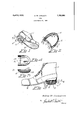
- Figure 1 is a perspective view of a shoe having the heel construction of my invention embodied therewith
- Fig. 2 is a perspective view in inverted position of the heel holder;
- Fig. 3 is a side View of a shoe with the heel portion shown in section for convenience of illustration
- Fig. 4 is a plan view of a modified form of rubber heel
- Fig. 5 is a sectional viewof this modified form of rubber heel.
- a shoedesignated as 1 provided with the usualsole 2 and heel portion 3.
- the holder shown in inverted position in Fig. 2 is a metal open frame. as indicated in Fig. 2 and. provided with an upper horizontal flange 4 in which are provided the necessary nail holes 5. for the nails N by means of. which the holder is permanently attached at the heel portion of the pried out-of the holder.
- the holder is fashioned with a retainang flange 6 conforming vto the shape of the heel and at the rear central portion of this flange a rigid retaining prong 7 is fashioned integral therewith and designed to penetrate the rubber heel.
- tongues as 8 which are struck from the flange and adapted to be flexed or bent outwardly therefrom prior to being fastened to the rubber heel.
- These tongues are provided with horizontal prongs 9 that are adapted to penetrate the sides and front portion of the rubber heel 10.
- the heel 10 is provided with a projecting bottom 11 and an upper recess 12 to insure a cushion action in'addition to the shock absorbing functions performed by the rubber heel.
- the rubber heel is attached to the holder by first inserting it within the holder and pushing the heel against the prong 7 so that the latter will penetrate the rear side of the heel. Thenafter the heel is in position within the holder the tongues 8 are forced inwardly causing the prongs 9 on these tongues to penetrate the rubber heel for the purpose of retaining it within the holder.
- the tongues 8 may be bent outwardly'by the use of a suitable tool to withdraw the prongs 9 from the worn rubber heel, and then the heel may be After a new heel is placed in position, the tongues 8 are again bent inwardly so that the prongs 9 will retain the new heel.
- a modified form of rubber heel 13 is shown having beveled edges 14 to enhance the resiliency of this rubber heel and prevent or minimize the liability ofcausing the heel to becaught on thetread portion of stairs or steps, or from being caught againstother objects.
Landscapes
- Footwear And Its Accessory, Manufacturing Method And Apparatuses (AREA)
Description
April 8, 1930. A. w. CARLSON HEEL Filed March 20. 1928 And/19w W aar'borz i Attorney Patented Apr. 8, 1930 UNITED STATES ANDREW W. CARLSON, F SPOKANE, WASHINGTON HEEL Application filed March 20, 1928. Serial No. 263,072.
My present invention relates to improve-' ments in heels for shoes and boots and of that type employing a rubber or composition heel member. The invention contemplates the use of a heel retalmngframe or holder preferably of metal having means for permanent attachment to the shoe and designed to receive and retain the usual rubber heel. The holder is constructed in such mannerthat the rubber 19 heel when worn may readily be removed and replaced by a fresh'or new'rubber heel, thus providing means whereby the heel portion of .the shoe may have a neat and attractive appearance at all times and at comparatively low cost of maintenance. I
The inven tion consists in certain novel cominations and arrangements between the shoe, the heel holder, and the heel, as will hereinafter he more fully set forth and claimed.
In the accompanying drawings, I have illustrated one complete example of the physical embodiment of the holder, together with two forms of rubber heels, wherein the parts are combined and arranged according to the best mode I have so far devised for the practical application of the principles of my invention.
Figure 1 is a perspective view of a shoe having the heel construction of my invention embodied therewith Fig. 2 is a perspective view in inverted position of the heel holder;
Fig. 3 is a side View of a shoe with the heel portion shown in section for convenience of illustration Fig. 4 is a plan view of a modified form of rubber heel; and
Fig. 5 is a sectional viewof this modified form of rubber heel.
In order that the general assembly and arrangement of parts may readily be understood, I have shown a shoedesignated as 1 provided with the usualsole 2 and heel portion 3. The holder shown in inverted position in Fig. 2 is a metal open frame. as indicated in Fig. 2 and. provided with an upper horizontal flange 4 in which are provided the necessary nail holes 5. for the nails N by means of. which the holder is permanently attached at the heel portion of the pried out-of the holder.
shoe. The holder is fashioned with a retainang flange 6 conforming vto the shape of the heel and at the rear central portion of this flange a rigid retaining prong 7 is fashioned integral therewith and designed to penetrate the rubber heel. 'At the sides and front portions of the retaining flange 6 are provided tongues as 8 which are struck from the flange and adapted to be flexed or bent outwardly therefrom prior to being fastened to the rubber heel. These tongues are provided with horizontal prongs 9 that are adapted to penetrate the sides and front portion of the rubber heel 10. The heel 10 is provided with a projecting bottom 11 and an upper recess 12 to insure a cushion action in'addition to the shock absorbing functions performed by the rubber heel. The rubber heel is attached to the holder by first inserting it within the holder and pushing the heel against the prong 7 so that the latter will penetrate the rear side of the heel. Thenafter the heel is in position within the holder the tongues 8 are forced inwardly causing the prongs 9 on these tongues to penetrate the rubber heel for the purpose of retaining it within the holder.
After the heel has become worn, the tongues 8 may be bent outwardly'by the use of a suitable tool to withdraw the prongs 9 from the worn rubber heel, and then the heel may be After a new heel is placed in position, the tongues 8 are again bent inwardly so that the prongs 9 will retain the new heel. v
In Figs. 4 and 5, a modified form of rubber heel 13 is shown having beveled edges 14 to enhance the resiliency of this rubber heel and prevent or minimize the liability ofcausing the heel to becaught on thetread portion of stairs or steps, or from being caught againstother objects. V
Having thus fully described my invention, what I claim as new anddesire tojsecure by Letters Patent is The combination with the heel portion of a shoe, of a holder comprising a nailing flan e having nail holes and nails for permanent y securing the holder to the heel portion of the 1 shoe, an integral retaining flange for the holder having a rigid prong and a rubber heel engaged by said prong, a plurality of downwardly projecting flexible tongues struck from the retaining flange, and prongs on the lower free ends of said tongues engaging the rubber heel.
In testimony whereof I affix my si nature.
AQW S W- Q B 9N-
Priority Applications (1)
| Application Number | Priority Date | Filing Date | Title |
|---|---|---|---|
| US263072A US1753692A (en) | 1928-03-20 | 1928-03-20 | Heel |
Applications Claiming Priority (1)
| Application Number | Priority Date | Filing Date | Title |
|---|---|---|---|
| US263072A US1753692A (en) | 1928-03-20 | 1928-03-20 | Heel |
Publications (1)
| Publication Number | Publication Date |
|---|---|
| US1753692A true US1753692A (en) | 1930-04-08 |
Family
ID=23000272
Family Applications (1)
| Application Number | Title | Priority Date | Filing Date |
|---|---|---|---|
| US263072A Expired - Lifetime US1753692A (en) | 1928-03-20 | 1928-03-20 | Heel |
Country Status (1)
| Country | Link |
|---|---|
| US (1) | US1753692A (en) |
Cited By (1)
| Publication number | Priority date | Publication date | Assignee | Title |
|---|---|---|---|---|
| US2597393A (en) * | 1947-04-14 | 1952-05-20 | Slampa Vavrin | Cushion heel |
-
1928
- 1928-03-20 US US263072A patent/US1753692A/en not_active Expired - Lifetime
Cited By (1)
| Publication number | Priority date | Publication date | Assignee | Title |
|---|---|---|---|---|
| US2597393A (en) * | 1947-04-14 | 1952-05-20 | Slampa Vavrin | Cushion heel |
Similar Documents
| Publication | Publication Date | Title |
|---|---|---|
| US1736609A (en) | Foot attachment | |
| US882109A (en) | Heel-support for shoes. | |
| US1471966A (en) | Heel | |
| US1753692A (en) | Heel | |
| US2234542A (en) | Rubber heel | |
| US2297552A (en) | Arch support | |
| US1897840A (en) | Ladder foot | |
| US2977691A (en) | Heel cup construction for ladies' overshoes | |
| US1684676A (en) | Sole construction for rubber boots | |
| US2137816A (en) | Shoe heel | |
| US1920170A (en) | Heel attachment device for shoes | |
| US2027482A (en) | Detachable heel | |
| US2149893A (en) | Detachable heel | |
| US1551345A (en) | Replaceable heel | |
| US1970254A (en) | Tread member for shoes | |
| US1034508A (en) | Ice-creeper. | |
| US1399447A (en) | Arch-support | |
| US1626489A (en) | Foot shield | |
| US1759034A (en) | Shoe construction | |
| US1642991A (en) | Heel-attaching device | |
| US2151341A (en) | Means for fastening attachable heels or soles to shoes | |
| US2193174A (en) | Arch support | |
| US1343638A (en) | Heel-attaching means | |
| US2301327A (en) | Heel fastener | |
| US1300070A (en) | Shoe-heel. |