US1753640A - Armature-conveying apparatus - Google Patents
Armature-conveying apparatus Download PDFInfo
- Publication number
- US1753640A US1753640A US289261A US28926128A US1753640A US 1753640 A US1753640 A US 1753640A US 289261 A US289261 A US 289261A US 28926128 A US28926128 A US 28926128A US 1753640 A US1753640 A US 1753640A
- Authority
- US
- United States
- Prior art keywords
- armature
- shaft
- support
- armatures
- hanger
- Prior art date
- Legal status (The legal status is an assumption and is not a legal conclusion. Google has not performed a legal analysis and makes no representation as to the accuracy of the status listed.)
- Expired - Lifetime
Links
- 239000002966 varnish Substances 0.000 description 8
- 238000001035 drying Methods 0.000 description 2
- 238000004804 winding Methods 0.000 description 2
- 238000005452 bending Methods 0.000 description 1
- 239000007788 liquid Substances 0.000 description 1
Images

Classifications
-
- B—PERFORMING OPERATIONS; TRANSPORTING
- B05—SPRAYING OR ATOMISING IN GENERAL; APPLYING FLUENT MATERIALS TO SURFACES, IN GENERAL
- B05C—APPARATUS FOR APPLYING FLUENT MATERIALS TO SURFACES, IN GENERAL
- B05C3/00—Apparatus in which the work is brought into contact with a bulk quantity of liquid or other fluent material
- B05C3/02—Apparatus in which the work is brought into contact with a bulk quantity of liquid or other fluent material the work being immersed in the liquid or other fluent material
- B05C3/09—Apparatus in which the work is brought into contact with a bulk quantity of liquid or other fluent material the work being immersed in the liquid or other fluent material for treating separate articles
- B05C3/10—Apparatus in which the work is brought into contact with a bulk quantity of liquid or other fluent material the work being immersed in the liquid or other fluent material for treating separate articles the articles being moved through the liquid or other fluent material
Definitions
- This invention relates to apparatus for conveying articles through a liquid bath and particularly for conveying the armatures of dynamo electric machines through a bath of varnish used to coat the armature wind- %)ne object of the present invention is to provide a simple and durable apparatus which will convey dynamo armatures through a varnish bath and whichwill protect the ends of the armature shafts from the varnish.
- Fig. 1 is a fragmentary diagrammatic view of the conveying apparatus embodying the present invention.
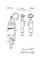
- Fig. 2 is a view on an enlarged scale of an armature suspended from one of the hangers of the conveyor shown in Fig. 1.
- Figs. 3 and 4 are plan and side views respectively of a modified form of hanger sleeve. j
- Figs. 5 and 6 are plan and side views respectively of a still further modified form of hanger sleeve. 7
- armature to which the present invention is adapted to be used is one comprising a shaft 20 carrymg a commutator 21 connected with armaturewlndings 22 wound upon a core 23 also attached to the shaft 20.
- the armature hanger is provided by bending a piece of wire so as to provide an intermediate loop 24 which surrounds the commutator 21 and which has a hook 25 received by anrannular groove 26 in a ring or collar 27 and with a portion 28 adapted to extend alongside the armature core 23 and terminatlng in a hook 29 adapted to engage any of a plurality of hooks 30 integral with a hanger cup or sleeve 31 providing a central socket for receiving the lower end of the armature shaft 20.
- the armature hanger conveyor is provided 1928. Serial No. zeaae 42. It will-be understood that the shaft 42 supports a similar sprocket-41 for supporting another chain 40 parallel to the one shown in thedrawing.
- the two chains 40 support between them a plurality of rods or u tubes 43 each carrying 'a plurality of collars 27 and hangershaving commutator 'embracing loops 24 and hooks 29.
- the sleeve 31 may be provided with a plurality of hooks 30 so that the sleeve 31 may be adapted to support thearmature at the proper distance so as to locate the commutator 21 within the loop 24 and at such a distance below the conveyor that all portions of the armature windings willbe submerged into the varnish bath.
- hanger sleeves ' which may be used with the same hangers which support the sleeves 31 shown in Figs. 1 and 2.
- the hanger sleeve is constructed so as to be adapted to support armatures having shafts varying in length and in diameter as well as to be adapted to support armature cores varying in length.
- Apparatus for conveying dynamo armatures comprising in combination, a travelling support, and means pivotally attached-to the support for holding substantially vertically an armature comprising an assembly of shaft,
- Apparatus according to claim 1 in which he ho in m an d s a d flector-protesti erp r on h matur hait V 8.
- Apparatus according toclaiml in pvhich the hold ng m n includes a de e-forenclosing the lower end of the, armature, shaft, .4, Apparatus for conveying dynamo armau es comp ng n o nat n, a travelling support and means pivotally attached to the support for supporting the armature by ,the lower end portion of its shaft, and including provisions for maintaining the armature in upright position.
- Apparatus-for conveying dynamo armatures comprising in combination, a travelling support, and means pivotally attached-to the support for supporting the armature by the lpwerendportion of its shaft and including a band encircling the commutator'i'n order to ,maintain the armature in upright-position.v '6.
- Apparat s for, conveying dynamo armatures comprising, incombination, a travelling support, a sleevefor receiving one end portion of the armatnreshaft and for supporting thearmature in an upright position by its lower end "and a hanger connecting the l ve th the s pport- 77:.
- Apparatus according to'iclaim 6 in which the hanger includes a bandiportion for encircling a portion of-the armature spaced fI Qm that endof its shaft which is received by the sleeve.
- n eyi g ynam h matures Comprising, in combination, a travelling unnort, u d l s-1 s t che lt t upport for holding an ar ature comprising asemb y f hafi, e e and windin s so hat one end of the shaft is uppermost, and hay:
Landscapes
- Manufacture Of Motors, Generators (AREA)
Description
April 8, 1930. R. w. BAKER ,7 3,
ARMATURE CONVEYING APPARATUS Filed June 29, 1928 2 Shets-Sheet 1 April 8, 1930. R. w. BAKER,
ARMATURE CONVEYING APPARATUS Filed June 29, 1928 2 Sheets-Sheet 2 g five Patented A 1930 UNITED STATES PATENT OFFICE RUSSELL W. BAKER, F ANDERSON, INDIANA, ASSIGNOB TO DELCO-REMY CORPORA- 'IION, OF DAYTON, OHIO, A CORPORATION OF DELAWARE ARMATURE-CONVEYING APPARATUS Application fi led June 29,
This invention relates to apparatus for conveying articles through a liquid bath and particularly for conveying the armatures of dynamo electric machines through a bath of varnish used to coat the armature wind- %)ne object of the present invention is to provide a simple and durable apparatus which will convey dynamo armatures through a varnish bath and whichwill protect the ends of the armature shafts from the varnish.
Further objects and advantages of the present invention will be apparent from the following description, reference being had to the accompanying drawings, wherein a preferred form of embodiment of the present invention is clearly shown.
In the drawings: 7 i
Fig. 1 is a fragmentary diagrammatic view of the conveying apparatus embodying the present invention.
Fig. 2 is a view on an enlarged scale of an armature suspended from one of the hangers of the conveyor shown in Fig. 1.
Figs. 3 and 4 are plan and side views respectively of a modified form of hanger sleeve. j
Figs. 5 and 6 are plan and side views respectively of a still further modified form of hanger sleeve. 7
The particular form of armature to which the present invention is adapted to be used is one comprising a shaft 20 carrymg a commutator 21 connected with armaturewlndings 22 wound upon a core 23 also attached to the shaft 20. Referring to Fig. 2, the armature hanger is provided by bending a piece of wire so as to provide an intermediate loop 24 which surrounds the commutator 21 and which has a hook 25 received by anrannular groove 26 in a ring or collar 27 and with a portion 28 adapted to extend alongside the armature core 23 and terminatlng in a hook 29 adapted to engage any of a plurality of hooks 30 integral with a hanger cup or sleeve 31 providing a central socket for receiving the lower end of the armature shaft 20.
The armature hanger conveyor is provided 1928. Serial No. zeaae 42. It will-be understood that the shaft 42 supports a similar sprocket-41 for supporting another chain 40 parallel to the one shown in thedrawing. The two chains 40 support between them a plurality of rods or u tubes 43 each carrying 'a plurality of collars 27 and hangershaving commutator 'embracing loops 24 and hooks 29.
. Before the armature is 'supportedon the conveyor for movement intothe bath of varnish supported in a vat 50- the end of the ar mature shaft whichis emerged is coated with oil before the protectingsleeve 31 'is placed upon it. Then the' assembled sleeve and armature are I assembled with the hanger as shown in Figs. 1 and 2. The hook 129 co operateswith' the sleeve 31 to support'the armature shaft by its lower end portion and the loop 24 cooperateswith'the commutator 21 so as tormaintain the armature in substantially vertical position." The hangers are pivotally supported upon the cross tubes 43 so that they will remain upright as they pass into andout ofthe varnish vat 50. It has been the practice to convey the armatures from the varnish vat into a varnish drying oven. After being conveyed from the drying oven, th'e armatures are removed from the hangers and the protecting sleeves 31 are removed from the armatures.
As armatures may varyin length of the armature core, the sleeve 31 may be provided with a plurality of hooks 30 so that the sleeve 31 may be adapted to support thearmature at the proper distance so as to locate the commutator 21 within the loop 24 and at such a distance below the conveyor that all portions of the armature windings willbe submerged into the varnish bath. Figs. 4-
and 16 show other forms of hanger sleeves 'which may be used with the same hangers which support the sleeves 31 shown in Figs. 1 and 2. The hanger sleeve is constructed so as to be adapted to support armatures having shafts varying in length and in diameter as well as to be adapted to support armature cores varying in length.
While the form of embodiment of the present invention as herein disclosed, constitutes a preferred form, it is to be understood that 'other for ns Inightbe adopted, allcoming within the scope of the claims-which follow. 7
What is claimed is as follows: 1. Apparatus for conveying dynamo armatures comprising in combination, a travelling support, and means pivotally attached-to the support for holding substantially vertically an armature comprising an assembly of shaft,
core and windings and having a part for directly receiving one end of the armature 1 Apparatus according to claim 1 in which he ho in m an d s a d flector-protesti erp r on h matur hait V 8. Apparatus according toclaiml in pvhich the hold ng m n includes a de e-forenclosing the lower end of the, armature, shaft, .4, Apparatus for conveying dynamo armau es comp ng n o nat n, a travelling support and means pivotally attached to the support for supporting the armature by ,the lower end portion of its shaft, and including provisions for maintaining the armature in upright position. i
5. Apparatus-for conveying dynamo armatures comprising in combination, a travelling support, and means pivotally attached-to the support for supporting the armature by the lpwerendportion of its shaft and including a band encircling the commutator'i'n order to ,maintain the armature in upright-position.v '6. Apparat s for, conveying dynamo armatures comprising, incombination, a travelling support, a sleevefor receiving one end portion of the armatnreshaft and for supporting thearmature in an upright position by its lower end "and a hanger connecting the l ve th the s pport- 77:. Apparatus according to'iclaim 6 in which the hanger includes a bandiportion for encircling a portion of-the armature spaced fI Qm that endof its shaft which is received by the sleeve. V
,8- Apparatu for n eyi g ynam h matures Comprising, in combination, a travelling unnort, u d l s-1 s t che lt t upport for holding an ar ature comprising asemb y f hafi, e e and windin s so hat one end of the shaft is uppermost, and hay:
ing means for enclosing the lower end por tio'nofthe shaft;
i In testimonygwhereofl hereto aflix m signature. 1
R SS L BA R-
Priority Applications (1)
| Application Number | Priority Date | Filing Date | Title |
|---|---|---|---|
| US289261A US1753640A (en) | 1928-06-29 | 1928-06-29 | Armature-conveying apparatus |
Applications Claiming Priority (1)
| Application Number | Priority Date | Filing Date | Title |
|---|---|---|---|
| US289261A US1753640A (en) | 1928-06-29 | 1928-06-29 | Armature-conveying apparatus |
Publications (1)
| Publication Number | Publication Date |
|---|---|
| US1753640A true US1753640A (en) | 1930-04-08 |
Family
ID=23110753
Family Applications (1)
| Application Number | Title | Priority Date | Filing Date |
|---|---|---|---|
| US289261A Expired - Lifetime US1753640A (en) | 1928-06-29 | 1928-06-29 | Armature-conveying apparatus |
Country Status (1)
| Country | Link |
|---|---|
| US (1) | US1753640A (en) |
Cited By (1)
| Publication number | Priority date | Publication date | Assignee | Title |
|---|---|---|---|---|
| US2460453A (en) * | 1944-10-09 | 1949-02-01 | Rudolph Miller | Safety hanger |
-
1928
- 1928-06-29 US US289261A patent/US1753640A/en not_active Expired - Lifetime
Cited By (1)
| Publication number | Priority date | Publication date | Assignee | Title |
|---|---|---|---|---|
| US2460453A (en) * | 1944-10-09 | 1949-02-01 | Rudolph Miller | Safety hanger |
Similar Documents
| Publication | Publication Date | Title |
|---|---|---|
| EP0095809A3 (en) | Apparatus for transferring slaughtered poultry | |
| US1753640A (en) | Armature-conveying apparatus | |
| CN204839022U (en) | Can prevent that clothing from elongating clothes hanger who warp | |
| KR101344894B1 (en) | Appratus for transferring of sleeve | |
| CN208532983U (en) | A kind of tow band tensioning apparatus for experimental branch line | |
| US2667660A (en) | Poultry picking shackle | |
| US1861368A (en) | Milk bottle carrier | |
| US2714223A (en) | Xpoultry s supporting and picking method | |
| US2209662A (en) | Method of supporting aerial cables | |
| CN210176995U (en) | Automatic feeding mechanism | |
| US1804775A (en) | Cabling clip | |
| CN205029525U (en) | Motor ribbon winding stator soaks process units immediately | |
| US1937398A (en) | Dual service mail crane | |
| US1477596A (en) | Means for supporting aerial cables | |
| CN213387146U (en) | Sliding wire hanging frame and transferring mechanism | |
| US1352549A (en) | Cable-hanger | |
| CN210429520U (en) | Transformer air duct fixing device and transformer with same | |
| US1870510A (en) | Device for carrying power lines | |
| US1404900A (en) | Trolley hanger | |
| US2070673A (en) | Garment hanger | |
| SU41915A1 (en) | Suspended chain conveyor | |
| US2299539A (en) | Device for handling articles | |
| JP3034771U (en) | Hanger material for overhead wire construction | |
| CN210506317U (en) | Convenient hangers part of food fermentation cylinder | |
| GB739195A (en) | Improvements in garment hangers |