US1745536A - Spraying apparatus - Google Patents
Spraying apparatus Download PDFInfo
- Publication number
- US1745536A US1745536A US79400A US7940026A US1745536A US 1745536 A US1745536 A US 1745536A US 79400 A US79400 A US 79400A US 7940026 A US7940026 A US 7940026A US 1745536 A US1745536 A US 1745536A
- Authority
- US
- United States
- Prior art keywords
- pin
- valve
- piston
- sprayer
- lever
- Prior art date
- Legal status (The legal status is an assumption and is not a legal conclusion. Google has not performed a legal analysis and makes no representation as to the accuracy of the status listed.)
- Expired - Lifetime
Links
Images

Classifications
-
- B—PERFORMING OPERATIONS; TRANSPORTING
- B05—SPRAYING OR ATOMISING IN GENERAL; APPLYING FLUENT MATERIALS TO SURFACES, IN GENERAL
- B05B—SPRAYING APPARATUS; ATOMISING APPARATUS; NOZZLES
- B05B3/00—Spraying or sprinkling apparatus with moving outlet elements or moving deflecting elements
- B05B3/02—Spraying or sprinkling apparatus with moving outlet elements or moving deflecting elements with rotating elements
- B05B3/04—Spraying or sprinkling apparatus with moving outlet elements or moving deflecting elements with rotating elements driven by the liquid or other fluent material discharged, e.g. the liquid actuating a motor before passing to the outlet
- B05B3/0412—Spraying or sprinkling apparatus with moving outlet elements or moving deflecting elements with rotating elements driven by the liquid or other fluent material discharged, e.g. the liquid actuating a motor before passing to the outlet comprising a liquid driven piston motor
-
- B—PERFORMING OPERATIONS; TRANSPORTING
- B05—SPRAYING OR ATOMISING IN GENERAL; APPLYING FLUENT MATERIALS TO SURFACES, IN GENERAL
- B05B—SPRAYING APPARATUS; ATOMISING APPARATUS; NOZZLES
- B05B1/00—Nozzles, spray heads or other outlets, with or without auxiliary devices such as valves, heating means
- B05B1/02—Nozzles, spray heads or other outlets, with or without auxiliary devices such as valves, heating means designed to produce a jet, spray, or other discharge of particular shape or nature, e.g. in single drops, or having an outlet of particular shape
- B05B1/08—Nozzles, spray heads or other outlets, with or without auxiliary devices such as valves, heating means designed to produce a jet, spray, or other discharge of particular shape or nature, e.g. in single drops, or having an outlet of particular shape of pulsating nature, e.g. delivering liquid in successive separate quantities
- B05B1/083—Nozzles, spray heads or other outlets, with or without auxiliary devices such as valves, heating means designed to produce a jet, spray, or other discharge of particular shape or nature, e.g. in single drops, or having an outlet of particular shape of pulsating nature, e.g. delivering liquid in successive separate quantities the pulsating mechanism comprising movable parts
-
- B—PERFORMING OPERATIONS; TRANSPORTING
- B05—SPRAYING OR ATOMISING IN GENERAL; APPLYING FLUENT MATERIALS TO SURFACES, IN GENERAL
- B05B—SPRAYING APPARATUS; ATOMISING APPARATUS; NOZZLES
- B05B3/00—Spraying or sprinkling apparatus with moving outlet elements or moving deflecting elements
- B05B3/14—Spraying or sprinkling apparatus with moving outlet elements or moving deflecting elements with oscillating elements; with intermittent operation
- B05B3/16—Spraying or sprinkling apparatus with moving outlet elements or moving deflecting elements with oscillating elements; with intermittent operation driven or controlled by the liquid or other fluent material discharged, e.g. the liquid actuating a motor before passing to the outlet
-
- Y—GENERAL TAGGING OF NEW TECHNOLOGICAL DEVELOPMENTS; GENERAL TAGGING OF CROSS-SECTIONAL TECHNOLOGIES SPANNING OVER SEVERAL SECTIONS OF THE IPC; TECHNICAL SUBJECTS COVERED BY FORMER USPC CROSS-REFERENCE ART COLLECTIONS [XRACs] AND DIGESTS
- Y10—TECHNICAL SUBJECTS COVERED BY FORMER USPC
- Y10T—TECHNICAL SUBJECTS COVERED BY FORMER US CLASSIFICATION
- Y10T137/00—Fluid handling
- Y10T137/2496—Self-proportioning or correlating systems
- Y10T137/2559—Self-controlled branched flow systems
- Y10T137/265—Plural outflows
- Y10T137/2668—Alternately or successively substituted outflow
- Y10T137/2693—Pressure responsive
Definitions
- pulsator Outlet so arranged that the exhaust water is directed on to the main stream from a jet so as to break it up adequately to water the ground between the sprayer and where thefstream would naturally fall, levers yby means of whichithe rotation of the sprayer is reversed, repeat mechanism by which lthe number of repeats is controlled and the water is finally shut'o, and an arrangement ofy stops for the timing mechanism when afsprayf fr er is used revolving onlyinfsemicircles.
- Figurel is a sectional elevation'ofa sprayer
- Figure 2r is a sectional elevation of the pulsator at the in posi- Y .tion
- Figure -3 is a sectional plan View of Figure 1 online A-B
- Figure 1 Figure 4 is a plan view of the quick action valve shown on Figure 5
- Figure 5 is an elevation of the quick action yvalve and the repeat mechanism
- Figure 6 is a partial oppositeside 3 f
- the sprayersr 1 see Figures 1, 2, 3, and 6, comprise a centre column 2 having an internal thread 3, a toothed portion 4, with stop pin holes 5, a bore 6, large ports 7, small ports 8, a thread 9, and a taper seat 10.
- the jet body 11 Fitting over the centre column 2 there is the jet body 11 provided with a taper bore 12 'which iit-s on the taper seat 10 of the said column 2 in such a manner as to be rotatable thereon, the jet body 11 being provided with a spiral screw 13, a jet supply pipe 14, a removable jet 15, the jet body pulsator 16 and an extension 17 to support the jet body rotating mechanism 18.
- the pulsator 16 comprises a cylindrical box 19l having a tangential cylinder 20, an inlet jet 21 from thesupply pipe14, and an outlet- 22. y v
- the cylindrical box 19 has a central boss 23, see Figure 3, on which ree to turn thereon is a rocker 24 having attached thereto a pin 25 and a strip of flat exible material such as leather 26 to act as a valve, a notcih 27 being cut in the rocker 24 to allow a stop pin 28 fastened to the box 19 to limit the motion of the said rocker 24 by coming in contact with shoulders 29 and 30 formed by the notch 27.
- crank! web 32and pin 33 being placed over the rocker 24 butin no way connected thereto except by tension spring 34 connecting the crankpin 33 and the rocker pin 25.
- a connecting rod 35 havingv a projection 36 passes between crank pin 33 and the pin 37 of a piston rod 38 on which is mounted piston 39 insidetangential cylinder 20.
- the piston rod 38 passes out of the cylinder 20 through gland nut 40 the end having attached thereto a cross head 41 to which is fitted aconnecting rod 42.
- the shaft 46 has a grooved portion 48 and two pins 49 and 50 attached theretothe pin 49 passing into a slotted hole 51 ofthe worm 45 and the pin 50 into either recesses 52 or 53 of ratchets 54 and 55 respectively mounted on the shaft 46.
- the ratchets 54 and 55 see Figures y9 and pin 49 being'able to slide within the slotted y vhole'51 ofthe worm k45 which is forced to alwaysturnwith'the shaft-46.
- VEngaged inthe ratchets 54 and 55 v (which have their teeth facin gin opposite directions) thereare pawls 56 and 57 respectively pressed inwardly by a.
- tensionv spring 58 the pawls 56 and 57 vbeing attached to one end of a link 59 swivelledon a pin 60 ⁇ attached to a boss 61 of the jet body 11, the-connecting'rod v42 passingbetween the crossl head-'41 and the opposite end'of the link 59-to which-the pawls 56rand 57 are fastened.
- the extension74 also 'carries la-n arm 78 which ⁇ passes downwardlyl andhas secured thereto by pin 79 asmall.engaging lever 80 free to liftbut unable to, droplower than the horizontal position.
- a setscrew 81 is fastened neary the top of the centre column 2-and' passes throughy the slots 73of the hollow piston rod 72..
- An adjustment setscrew 82 passes through the topy ofthe hollow piston rod 72 and comes in contact with the setscrew 81.
- a piece of pipe ⁇ 83 is screwed into the in;V ternal thread 3 of the center column 2 and passes down and is attached to an upper seat casting 84 screwed into the top of a check valve body 85.
- the repeat control mechanism comprises an ordinary quick action stop valve 92having a side spindle 93 which f, opensand closes'the'valve 92 by .being turned a fewdegrees.l 1
- the ratchet 98A has a raised projectionlOO between two Vof the teeth, the projection 100 beingvof such aszefthat a notchY 101 of'a pawl102Aa-ttachedto lever 94 will fit neatly thereon.- Y
- a pawl 103 attachedtothe body ofthe valve 92 also engages in the ratchet 98'.'V ⁇ A strip*y spring 104 presses thelever pawl 102 into the ratchetA 98.
- a small pi-pe 105 supplies water from the last sprayer 1 of the series to the quick action valve 92 controlbucket 95,'fsee Figure 11, i
- the bucket 95 and the latter ascends turning the spindle 93 back and again opening the quick action stop valve 92 the water again flowing to the iirst sprayer 1 of the series and so onnuntil the Vwater again flows from the small pipe to the bucket 95.
- This cycle of operation can be repeated as often as desired and then stopped by means of th-e ratchet 98 fitted to the quick action valve 92 spindle 93.
- Each tooth represents one .cycleV ofopera'- tion of the sprayers and the ratchet 98 is turned round' until at oneofthe down strokes of the bucket 95 the pawl 102is engaged in the tooth with the projection 100 between it and the next tooth.
- the sprayer l operates the-same as before described except that when the jet body 11 is revolving around the center column 2,l see Figure 3, the lever 66 comes .in contact with one of the'pins lll whichgradually forces itV radially away Vfrom the stop pin 68 against the tensionfof spring 70 until the line ofthe said spring 70 between spring pins 64'and69 is past the center of the swivel pinGSVand-the y tension of the spring 70 pulls the lever 66 against stop pin'67 and the lever 62 towards that side of the swivel pin 63..'
- Aisprayer arranged for rotation, mecha# Y nism to rotate vthe sprayer, and pressure actuatedmeansconnectedto the sprayer and-ar'- ranged-to actuatesaid mechanism, said means comprising a bodyforming a chamberanda cylinder and connected to and communicate ing'with the interior ofthe sprayer, a pist-on inlsaid cylinder to which Ytherotating mechanism is connected, a member arranged for oscillation in'said -chamber and provided withl a valve, acrankmounted'at the axis of oscillas tion and o f said oscillating member and for, ⁇
- VmovementA independentlyy thereof, alconnectl ing rod between said vcrank andfsaid piston, a
- a sprayer including" a.l central column and having a timing mechanism eomprisinga jet body mounted for Iturning movement on said column and provided withspiral threads, apistonf-valve in said r'column movable-in one direction by pressure of waterjin'v Sai'dcolev umn, a spring to move saidpistonval've'in the reverse directionl when thejwaterv pressure die ininishesat'the endfof the stroke of'said pis-l ton valve, and a memberengageable with the threads and connectedto Vsaid piston valve to retard"V thev movementof the-*latter by water f pressure.
- a sprayer including a centrall column' and havingjatimin ⁇ mechanism comprising a jet body mounted or turning lmovement on said column andprovided with'spiral threads, a piston valvein said column .movable inon'e direction' by pressure ofiwaterin said column, a springto move ⁇ said :pist-on' valvev inthe re;l verse direction whenthe; water f pressure vdiminishesfatthe, end ofthe vstroke of' said Ap iston valve, andamemb'er”engageable withthe threads and connected to saidpiston valve toy retard,l the movement of the latter'jby -water pressurejandmeans to predetermine the eX- Y tent of movement ofsaid piston valve.
Landscapes
- Catching Or Destruction (AREA)
Description
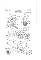
Feb. 4, 1930. E. G. GREsHAM SPRAYING APPARATUS Filed Jan. 5. 1926 2 sheets-smet 1 im /5 A\ v 9. u.. o Y ,A 5 5 6 6 o C @a c N/ Y.
Feb. 4, 1930.
E. G. GRESHAM s-PRAYING APPARATUS Filed Jan. 5, 1926 2 sneetsl-sneet '2 'Patented Feb. 4, 1930 ERNESTy eno'oME GRESHAM, orl AUCKLAND, NEW zEArmiank SPRAYING APPARATUS Appcaton filed January 5, 1926, Serial No. 79,400, and in New Zealand February 5, 1925.
This inventionrelatesto improvements in spraying apparatus. The object aimed at by this invention is to effect improvements in the construction of such apparatus whereby greater efficiency, economy and ycertainty ofv 'y action'are secured. y
VThe invention comprises a timing gear f completecausing the uncovering or' small [ports which allow ka sudden rush of water l0 past a specially designed valve which is lifted and shuts off the water from that particular-sprayer and opens the water to the next sprayer of the series, a rotationpulsator, a
pulsator Outlet so arranged that the exhaust water is directed on to the main stream from a jet so as to break it up suficiently to water the ground between the sprayer and where thefstream would naturally fall, levers yby means of whichithe rotation of the sprayer is reversed, repeat mechanism by which lthe number of repeats is controlled and the water is finally shut'o, and an arrangement ofy stops for the timing mechanism when afsprayf fr er is used revolving onlyinfsemicircles.
In the accompanying drawings illustratling the invention, Figurel is a sectional elevation'ofa sprayer, Figure 2ris a sectional elevation of the pulsator at the in posi- Y .tion,`Figure -3is a sectional plan View of Figure 1 online A-B, Figure 1, Figure 4 is a plan view of the quick action valve shown on Figure 5, Figure 5 is an elevation of the quick action yvalve and the repeat mechanism, Figure 6 is a partial oppositeside 3 f,
elevation to that shown in Figure 1, Figure 7 isa partial perspective View of notched portion which takes the place of spiral thread onthe top of the kjet body when reverse 0' mechanism is used, Figure 8 is a sectional plan view of Figure17, Figure 9 is an elevation' of one ofthe rotating mechanism ratchets, Figure 10 is a sectional plan on line A A-B of Figure 9,`Figure 10A is a detail sectional view of the same, Figure 11 is aperdetail sectional View of :the valve 92 and its connections.
The sprayersr 1, see Figures 1, 2, 3, and 6, comprise a centre column 2 having an internal thread 3, a toothed portion 4, with stop pin holes 5, a bore 6, large ports 7, small ports 8, a thread 9, and a taper seat 10.
Fitting over the centre column 2 there is the jet body 11 provided with a taper bore 12 'which iit-s on the taper seat 10 of the said column 2 in such a manner as to be rotatable thereon, the jet body 11 being provided with a spiral screw 13, a jet supply pipe 14, a removable jet 15, the jet body pulsator 16 and an extension 17 to support the jet body rotating mechanism 18.
The pulsator 16 comprises a cylindrical box 19l having a tangential cylinder 20, an inlet jet 21 from thesupply pipe14, and an outlet- 22. y v
The cylindrical box 19 has a central boss 23, see Figure 3, on which ree to turn thereon is a rocker 24 having attached thereto a pin 25 and a strip of flat exible material such as leather 26 to act as a valve, a notcih 27 being cut in the rocker 24 to allow a stop pin 28 fastened to the box 19 to limit the motion of the said rocker 24 by coming in contact with shoulders 29 and 30 formed by the notch 27.
The piston rod 38 passes out of the cylinder 20 through gland nut 40 the end having attached thereto a cross head 41 to which is fitted aconnecting rod 42.
A. tension spring 43 fastened between connecting rod projection 36 and the box 19 tends to keep the piston 39 atthe in posi- 9 worm 45 in gear with the toothed portion i 4 of the centre column 2, the said worm 45 being mounted on a shaft 46 slidably and revolvably mounted in the'extension 17 of the jet body 11 and an extended support 47.
The shaft 46 has a grooved portion 48 and two pins 49 and 50 attached theretothe pin 49 passing into a slotted hole 51 ofthe worm 45 and the pin 50 into either recesses 52 or 53 of ratchets 54 and 55 respectively mounted on the shaft 46.
The ratchets 54 and 55, see Figures y9 and pin 49 being'able to slide within the slotted y vhole'51 ofthe worm k45 which is forced to alwaysturnwith'the shaft-46. VEngaged inthe ratchets 54 and 55 v (which have their teeth facin gin opposite directions) thereare pawls 56 and 57 respectively pressed inwardly by a. tensionv spring 58, the pawls 56 and 57 vbeing attached to one end of a link 59 swivelledon a pin 60 `attached to a boss 61 of the jet body 11, the-connecting'rod v42 passingbetween the crossl head-'41 and the opposite end'of the link 59-to which-the pawls 56rand 57 are fastened.
At the grooved portion 48 of the shaft 46 there is the mechanism forImaking the shaft 46 slide backwards and forwards so that the pin fwillvpass between recesses 52 and 53 of ratchets 54 and 55 and take up their opposite` rotations; j
This mechanism comprises a lever 62 swivelled on pin 63 havingy a spring pin'64 at its outer end and an engaging pin 65 at its other endpassing into the grooved'shaft portion 48. y .K Also swivelledon'pin 63 there is another v lever-66 `(between stop pinsv67 and 68) -provided with a springpin 69jfrom which a tension spring 7 Opasses to the spring pin 64 of-.the lever 62. Y A,
Fitting into the bore 6,' see Figure 1,' yof the center column 2 there isa pistonY71-with a hollow piston rody 72 withvtwo oppositely Yplaced slots 73 the vupperend' ofy thefpiston rod being extended as at? 74A to take a tene sionk spring l75 which passes downl andis fastened to a lock pin 76 of coll-a'r77' on the thread 9 of centre column 2:
The extension74 also 'carries la-n arm 78 which` passes downwardlyl andhas secured thereto by pin 79 asmall.engaging lever 80 free to liftbut unable to, droplower than the horizontal position.
A setscrew 81 is fastened neary the top of the centre column 2-and' passes throughy the slots 73of the hollow piston rod 72..
An adjustment setscrew 82 passes through the topy ofthe hollow piston rod 72 and comes in contact with the setscrew 81.
A piece of pipe`83 is screwed into the in;V ternal thread 3 of the center column 2 and passes down and is attached to an upper seat casting 84 screwed into the top of a check valve body 85..
The repeat control mechanism, see Figures `4 and 5, comprises an ordinary quick action stop valve 92having a side spindle 93 which f, opensand closes'the'valve 92 by .being turned a fewdegrees.l 1
To this spindle93 is fasteneda leverv 94 having an opentopped bucket V95 (provided with a drain cock 96) attached atone end f valve 92. v
Mounted lon the spindle 93 and'free: t turn thereonthere is a ratchet 98 prevented from working olf thesaid spindle 93by a collar 99.
The ratchet 98Ahas a raised projectionlOO between two Vof the teeth, the projection 100 beingvof such aszefthat a notchY 101 of'a pawl102Aa-ttachedto lever 94 will fit neatly thereon.- Y
' and al balance weight 97 atV theother, the
A pawl 103 attachedtothe body ofthe valve 92 also engages in the ratchet 98'.'V `A strip*y spring 104 presses thelever pawl 102 into the ratchetA 98.
A small pi-pe 105 supplies water from the last sprayer 1 of the series to the quick action valve 92 controlbucket 95,'fsee Figure 11, i
and the main 106 supplies water through main valve 107 to the sprayer pipe line 108.y
- For a reversing sprayer working in semi circles instead of a spiral screw 13 on the jet body lltheref is a series ofgrooves 109, see Figure 7, which haveslots Y11() left at opposite sidesof each alternate groove-109.
Pins lllfareplaced as desired in the stop pin holes '5, to come lincontact with the lever through the inlet jetf21`to'the cylindrical'box V19 of the pulsa-tor 16 pressure increasing lin the rsaid'box 19 forcing the piston 39 out against the tension of spring 43.
.The piston .rod 38being forcedvout draws the connecting rod which moves the crankypin 33 radially until the line of the spring 34 ,between the pin on the rocker 24and the vcrankpin33 is past the centre vof the crank- .shaft 31, the spring4 34 then pulls the rocker 24 round until rocker shoulder29 comes in contact withthe stop pin 28, the pulsator being 21 allows the water under pressure `in box 19 toescape quickly, thepressure on the piston v39 thennot being sufficient toy resist the tension of the spring 43, the latter draws the piston 39 back again, the connecting rod 35 forcing crankpin 33 round radially to its original position, the spring 34 having passed the Y crankshaft V31 center, the rocker 24 is turned back to its original position with rocker shoulder vagainst the stop pin 28,the valve 246 coveringthe outlet pipe 22.
`The pulsator 16-is then in the position as shown in Figure 2 allowing the pressure in thebox 19 to again accumulate and move the piston 39 again and so on.
This continual reciprocating motion of the y piston rod 38 is conveyed through crosshead 41andco'nnecting rod 42 to link 59 of the rotating mechanism 18. y f @This link 59 rocks backwards'and forwards on pin 60 and the pawls 56 and 57 also rock likewise ybut being engaged in'ratchets 54 andy 55 respectively, on the forward strokes of the pulsatofr 16 the pawl 56 .turns ratchet 54 one tooth in a clockwise direction `and pawl 57 turns ratchet 55 `in an anti-clockwise direction. f
Considering Figure 3 the pin 50 .ofy shaft 46being in the recess53 of the ratchet k5,5 (between notches 55A, see Figures 9 andlO) the yanti-clockwise` rotation of the ratchet 55 is Vconveyed .to the shaft 46 andthe pin 49 in the y latter causes the worm to also turn which being in gear with the toothed portion 4 of.
' Pressurey of water inside the'bo're 6l ofthe i center column`2 tends to force the piston 71 upwardly butis prevented from so doing by the engaging lever being engaged in the ,Y spiral thread 13.
. gaging leverl 8O stationary, as the jet body 11 turns the engaging lever 80 screws higher up the spiral thread 13 the piston 71 also getting higher up the bore 6 until engaging lever 80`is clear'of the spiral kthread 13 the piston is forced up the bore 6 uncovering the ports 8 allowing water to flow therefrom.
As the increase of flow through the pipe 83 due to uncovering of ports 8 has resulted ina drop of pressure but an increase of velocity through the notches of the valve 87 the latter is raised by the flow of water, untilthe ,upper seating surface 89 of the valve 87 comes in contact with the seat 91 of the upper seat casting 84 the waterbeing then cut off from the jet 15 but able to flow through the check valve body 85, and the pipe line 108 to the next sprayer l.
vThis next sprayer works in exactly the 4 same manner as above described one sprayer 1 stopping and the following one connecting until all the sprayers have stopped and the water is opened to the pipe 105, see Figure 11.
kThis pipe 105 allows water to flow into the bucket 95, see Figures 4, 5 and 11 and the weight ofwater in the bucket becoming greater than the balance weight 97 the bucket 95y descends and the lever 94 turns spindle 93and the quick action valve 92 is closed.
Just prior to the closing of the stop valve 92 all the valves 87 of the sprayers 1 are in the upposition with 'their seatings 89 on seats 91 kept in this position by the pressure of water. l
As each jet 15 is cut off from the pressure the tension spring 75 between extension 74 and the lock pin 76 draws the piston rod 72 and piston 71 downwardly into the bore 6 the levers`80 lift over thel spiral threads 13 until the piston 71 is right down according to the vadjustment of setscrew 82 which can control the number of revolutions of the jet body 11 until the relieving of pressure by the piston 71 uncovering ports 8. Thus the timing mechanism is. again i position for a number of revolutions of the jet body 11.
At the closing of the quick action valve 92 the pressure in the pipe line 108 drops and g the valves 87 in the sprayers 1 drop and the water nowing into the bucket 95 ceases.
As the water is slowly flowing out of the bucket 95 through the open cock 96 the weight of the balance weight 97 becomes greater than y,
the bucket 95 and the latter ascends turning the spindle 93 back and again opening the quick action stop valve 92 the water again flowing to the iirst sprayer 1 of the series and so onnuntil the Vwater again flows from the small pipe to the bucket 95.
. This cycle of operation can be repeated as often as desired and then stopped by means of th-e ratchet 98 fitted to the quick action valve 92 spindle 93.
At .each down stroke of the bucket 95 the pawl 102 0n lever 94 turns the ratchet 98 one tooth and on the up stroke of the bucket 95 the ratchet 98 is prevented from turning back by the pawl 103 attached` to the valve body 92 iso engagingin a tooth'of theratchet 98. the `lever Y pawl 102 `slipping-over vthe teeth'. L f
Each tooth represents one .cycleV ofopera'- tion of the sprayers and the ratchet 98 is turned round' until at oneofthe down strokes of the bucket 95 the pawl 102is engaged in the tooth with the projection 100 between it and the next tooth. A
As this projection 100 fits into a notch v101 in the pawl 102, on the bucket95 attempting to ascend it is unable to do so because the pawl 102 is `unable to slip over the ratchet 98 teeth and attempts to turn* the ratchet 98 back'but is unable to do so because of the pawl 108 Thus the bucket 95 is kept locked'down and the quick action valve 92 closed until the pawl i102 is again released by the operator. who can control the number of cycles of vvspraying by turning the vratchet 98 backthe desired'number of teeth.
The operation above described is for a sprayer revolving'continually in the one direction and the stop pins 111 arenot used.
For a sprayer l to sprayin a semiecircle two pins lll are fitted into the holes 5 Aopposite each other and in place of the spiral thread 13 there are a series oflgrooves 109,' see vFigurev7.
The sprayer l operates the-same as before described except that when the jet body 11 is revolving around the center column 2,l see Figure 3, the lever 66 comes .in contact with one of the'pins lll whichgradually forces itV radially away Vfrom the stop pin 68 against the tensionfof spring 70 until the line ofthe said spring 70 between spring pins 64'and69 is past the center of the swivel pinGSVand-the y tension of the spring 70 pulls the lever 66 against stop pin'67 and the lever 62 towards that side of the swivel pin 63..'
This movement'of the lever 62causesthe engaging pin 65 in the grooved portion 48 of shaft 46 to slide the latter inwardly andthe pin 50 passes from the recess 53 of ratchet 55V to the recess '52 of ratchet 54and as the latter,v Y
is turning in the opposite directionA togthe' ratchet the shaft 46 yand worm45 also take up this reversed rotation so that the jet bodys ll commences to revolve in the oppositedi'recl tion until the lever 66 COmesinCOntactwith the other pin 111 which forces it away 'fromy stop pin 67 over to stop pin 68 the shaft 46 being'caused to slide out again to, the'position shown in'Figure 3 the, rotation*thus/being" again reversed and so on. v
With this type of sprayer when the jetpbody 11 has turned halfa revolution theengaging lever comes under one of theslots 110 inthe grooves 109, see Figure 7, and the .pressure onA the piston 7l causes the lever 8() 'to jump through the yslot 110 to the next groove up around which it moves during the return half' revolution andumps through the slotlll) in the groove at the opposite side to the previousV slot 110 the vrerersing'of'the'jet body taking the uppermost'slot llOand the pistonl is i free to lift and uncover the/ports 8-the operation l of. 'the sprayer ib'eing :then-l justf as prepviouslyf'described; -l y 1. Aisprayerarranged for rotation, mecha# Y nism to rotate vthe sprayer, and pressure actuatedmeansconnectedto the sprayer and-ar'- ranged-to actuatesaid mechanism, said means comprising a bodyforming a chamberanda cylinder and connected to and communicate ing'with the interior ofthe sprayer, a pist-on inlsaid cylinder to which Ytherotating mechanism is connected, a member arranged for oscillation in'said -chamber and provided withl a valve, acrankmounted'at the axis of oscillas tion and o f said oscillating member and for,`
VmovementA independentlyy thereof, alconnectl ing rod between said vcrank andfsaid piston, a
yspring lconnected to said oscillating member andsaidfcrank'andshiftable to opposite sides ofthecenter of oscillation of said oscillating vmember and a vspring exertingitsltension to impart instroke to said piston. e
- 2. A sprayer including" a.l central column and having a timing mechanism eomprisinga jet body mounted for Iturning movement on said column and provided withspiral threads, apistonf-valve in said r'column movable-in one direction by pressure of waterjin'v Sai'dcolev umn, a spring to move saidpistonval've'in the reverse directionl when thejwaterv pressure die ininishesat'the endfof the stroke of'said pis-l ton valve, and a memberengageable with the threads and connectedto Vsaid piston valve to retard"V thev movementof the-*latter by water f pressure.
3. A sprayer including a centrall column' and havingjatimin `mechanism comprisinga jet body mounted or turning lmovement on said column andprovided with'spiral threads, a piston valvein said column .movable inon'e direction' by pressure ofiwaterin said column, a springto move `said :pist-on' valvev inthe re;l verse direction whenthe; water f pressure vdiminishesfatthe, end ofthe vstroke of' said Ap iston valve, andamemb'er"engageable withthe threads and connected to saidpiston valve toy retard,l the movement of the latter'jby -water pressurejandmeans to predetermine the eX- Y tent of movement ofsaid piston valve.
InV testimonyk whereoffl aiiX 'my signature.
ERNEST GROOME GRESHAM
Applications Claiming Priority (1)
| Application Number | Priority Date | Filing Date | Title |
|---|---|---|---|
| NZ1745536X | 1925-02-05 |
Publications (1)
| Publication Number | Publication Date |
|---|---|
| US1745536A true US1745536A (en) | 1930-02-04 |
Family
ID=19917118
Family Applications (1)
| Application Number | Title | Priority Date | Filing Date |
|---|---|---|---|
| US79400A Expired - Lifetime US1745536A (en) | 1925-02-05 | 1926-01-05 | Spraying apparatus |
Country Status (1)
| Country | Link |
|---|---|
| US (1) | US1745536A (en) |
Cited By (6)
| Publication number | Priority date | Publication date | Assignee | Title |
|---|---|---|---|---|
| US3042074A (en) * | 1959-01-12 | 1962-07-03 | Graybill Ind Inc | Fluid distribution systems and controlling fluid motor with piston actuated reversing valve means |
| US3080881A (en) * | 1958-10-13 | 1963-03-12 | Fmc Corp | Sequential irrigation valve |
| DE1200053B (en) * | 1958-10-13 | 1965-09-02 | Fmc Corp | Valve for controlling the liquid delivery of sprinklers arranged on lines |
| US3964685A (en) * | 1974-04-09 | 1976-06-22 | Carpano & Pons S.A. | Lawn sprinkling and similar installations |
| US4335852A (en) * | 1980-05-01 | 1982-06-22 | Beatrice Foods Co. | Device for controlling the flow of fluid |
| DE102012016007A1 (en) * | 2012-08-11 | 2014-02-13 | Dieter Mühlenbruch | Hollow nozzle for fire fighting, has hollow jet nozzle in which axially movable cone shaped beam is placed in jet and spray jet positions and is moved by crank mechanism alternately in rapid succession from jet to spray jet positions |
-
1926
- 1926-01-05 US US79400A patent/US1745536A/en not_active Expired - Lifetime
Cited By (6)
| Publication number | Priority date | Publication date | Assignee | Title |
|---|---|---|---|---|
| US3080881A (en) * | 1958-10-13 | 1963-03-12 | Fmc Corp | Sequential irrigation valve |
| DE1200053B (en) * | 1958-10-13 | 1965-09-02 | Fmc Corp | Valve for controlling the liquid delivery of sprinklers arranged on lines |
| US3042074A (en) * | 1959-01-12 | 1962-07-03 | Graybill Ind Inc | Fluid distribution systems and controlling fluid motor with piston actuated reversing valve means |
| US3964685A (en) * | 1974-04-09 | 1976-06-22 | Carpano & Pons S.A. | Lawn sprinkling and similar installations |
| US4335852A (en) * | 1980-05-01 | 1982-06-22 | Beatrice Foods Co. | Device for controlling the flow of fluid |
| DE102012016007A1 (en) * | 2012-08-11 | 2014-02-13 | Dieter Mühlenbruch | Hollow nozzle for fire fighting, has hollow jet nozzle in which axially movable cone shaped beam is placed in jet and spray jet positions and is moved by crank mechanism alternately in rapid succession from jet to spray jet positions |
Similar Documents
| Publication | Publication Date | Title |
|---|---|---|
| US1745536A (en) | Spraying apparatus | |
| US1541216A (en) | Lock valve | |
| US1822388A (en) | Steaming valve for garment presses | |
| DE736778C (en) | Fluid pump with compressed air drive | |
| US342073A (en) | Block-presser for paper-pulp mills | |
| US1381562A (en) | Pump | |
| US528275A (en) | Engine-reversing gear | |
| US1575767A (en) | Pump | |
| US1276681A (en) | Steam-engine. | |
| US1855433A (en) | Valve | |
| DE8913C (en) | Piston control for steam engines, pumps and water motors | |
| DE333608C (en) | Pressure regulator for pipes fed with exhaust steam and live steam | |
| DE385528C (en) | Device for topping up air in an air chamber using a valveless fluid pump | |
| US1180238A (en) | Water-motor. | |
| US1226840A (en) | Float-controlled valve for water systems. | |
| DE56465C (en) | Piston water meter | |
| DE458193C (en) | Hand ram operated by compressed air | |
| US1476944A (en) | Controlling device for meters | |
| US1964340A (en) | Fluid motor | |
| US1346289A (en) | Valve | |
| US210055A (en) | Improvement in pumps | |
| US1181259A (en) | Regulating device for washing sugar. | |
| US112722A (en) | Improvement in meters | |
| US898516A (en) | Water-motor. | |
| US114506A (en) | Improvement in steam pumping-engines |