US1714975A - X-ray anode - Google Patents
X-ray anode Download PDFInfo
- Publication number
- US1714975A US1714975A US679525A US67952523A US1714975A US 1714975 A US1714975 A US 1714975A US 679525 A US679525 A US 679525A US 67952523 A US67952523 A US 67952523A US 1714975 A US1714975 A US 1714975A
- Authority
- US
- United States
- Prior art keywords
- anode
- passage
- mass
- rays
- metal
- Prior art date
- Legal status (The legal status is an assumption and is not a legal conclusion. Google has not performed a legal analysis and makes no representation as to the accuracy of the status listed.)
- Expired - Lifetime
Links
- 229910052751 metal Inorganic materials 0.000 description 14
- 239000002184 metal Substances 0.000 description 14
- 239000003870 refractory metal Substances 0.000 description 6
- WFKWXMTUELFFGS-UHFFFAOYSA-N tungsten Chemical compound [W] WFKWXMTUELFFGS-UHFFFAOYSA-N 0.000 description 4
- 229910052721 tungsten Inorganic materials 0.000 description 4
- 239000010937 tungsten Substances 0.000 description 4
- RYGMFSIKBFXOCR-UHFFFAOYSA-N Copper Chemical compound [Cu] RYGMFSIKBFXOCR-UHFFFAOYSA-N 0.000 description 3
- 238000010276 construction Methods 0.000 description 3
- 229910052802 copper Inorganic materials 0.000 description 3
- 239000010949 copper Substances 0.000 description 3
- 239000007787 solid Substances 0.000 description 3
- OKTJSMMVPCPJKN-UHFFFAOYSA-N Carbon Chemical compound [C] OKTJSMMVPCPJKN-UHFFFAOYSA-N 0.000 description 2
- 238000005266 casting Methods 0.000 description 2
- 229910002804 graphite Inorganic materials 0.000 description 2
- 239000010439 graphite Substances 0.000 description 2
- BASFCYQUMIYNBI-UHFFFAOYSA-N platinum Chemical compound [Pt] BASFCYQUMIYNBI-UHFFFAOYSA-N 0.000 description 2
- 241001663154 Electron Species 0.000 description 1
- 101001005711 Homo sapiens MARVEL domain-containing protein 2 Proteins 0.000 description 1
- ZOKXTWBITQBERF-UHFFFAOYSA-N Molybdenum Chemical compound [Mo] ZOKXTWBITQBERF-UHFFFAOYSA-N 0.000 description 1
- 239000002131 composite material Substances 0.000 description 1
- 230000000694 effects Effects 0.000 description 1
- 239000011521 glass Substances 0.000 description 1
- 238000005338 heat storage Methods 0.000 description 1
- 239000000463 material Substances 0.000 description 1
- 150000002739 metals Chemical class 0.000 description 1
- 238000000034 method Methods 0.000 description 1
- 229910052750 molybdenum Inorganic materials 0.000 description 1
- 239000011733 molybdenum Substances 0.000 description 1
- 229910052697 platinum Inorganic materials 0.000 description 1
- 238000007789 sealing Methods 0.000 description 1
- 229910052709 silver Inorganic materials 0.000 description 1
- 239000004332 silver Substances 0.000 description 1
Images
Classifications
-
- H—ELECTRICITY
- H01—ELECTRIC ELEMENTS
- H01J—ELECTRIC DISCHARGE TUBES OR DISCHARGE LAMPS
- H01J35/00—X-ray tubes
- H01J35/02—Details
- H01J35/16—Vessels; Containers; Shields associated therewith
Definitions
- the present invention comprises an improved ncw target for X-ray tubes, wh ch is cap: ble of increasing the energy capaclty of an X-ray tube, and which confines the emission of X-rays to a restricted zone so as to protect the operator.
- anode which is constructed as later explained, to enable X-rays to be generated at or near the center of the mass of the head which acts both as a heat reservoir and as a shield.
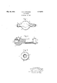
- FIG. 1 shows in outline an X-ray tube containing an anode embodying my invention
- Fig. 2 shows my improved anode partly in longitudinal section
- Fig. 3 is an end view of the same.
- my im roved mode comprises a knob-shaped mass .0 metal which in the specific embodiment illustrated comprises a relatively thick cylindrical stem 1' and a substantially spherical head 2, although of course, these exact geometric confi rations are not essential.
- These portions 0 the anode preferably consist of a metal of good heat conductivity, for example, cop
- a plate or disc 3 consisting of a highly refractory metal of high atomic number, such for example, as tungsten, is embedded at or near the center of the head. A good metallic union is insured by casting copper about the tungsten plate, as described in my prior Patent 1,162,339 of November 30, 1915.
- the plate 3 may be held temporarily by small molybdenum or tungsten wlres upon a plug of graphite (not shown) which when removed after casting leaves the passage 4 in the anode head.
- the plate 3 which may be termed the target on which X-rays are generated, is preferably placed at an angle to the longitudinal axis of the anode, as illustrated.
- the passageway 4 extends from the exter1or to the target plate 3 substantially in line with the longitudinal axis of the anode.
- a second passage 6 extends substantially at rlght angles to the passage 4.
- This passage also may be formed by a graphite plug suitably positioned in the mold.
- the anode is mounted in a bulb 7 (Fig. 1) by sealing the cone-shaped flange 8, which consists of platinum, or other suitable material into the arm of the glass bulb.
- the stem 1 pro ects out of the bulb and serves to carry heat to the exterior where it may be dissipated either by a radiator (not shown) or by a surrounding body of oil.
- the cathode which is of the usual construction, as described for example in my prior Patent 1,211,092, is mounted opposite the anode.
- the bulb is exhausted by well-known methods.
- the heat is generated at the centre of a mass of metal, which is substantially of spherical shape so that heat can flow with equal readiness in substantially all directions.
- anode comprising a knob-shaped mass of metal of good heat conductivity, said mass having a passage extending from the exterior to a substantially central portion of said mass, a plate of refractory metal located at the end of said passage and in alignment with the direction of electron flow from said cathode, a second passage at right angles to said first mentioned passage said plate being adapted to emit electrons through said second passage, said cathode structure being closely adjacentto said anode whereby it may act as a shield for undesired X-rays.
- An X-ray anode comprising an integral, substantially spherical mass of copper having a passage extending from the exterior to a substantially central portion thereof, a plate of refractorymetal located at the end of said passage, an integral solid stem in alignment with said passage, and a second passage substantially at right angles to and intersecting said first mentioned passage substantially at the center of mass of said anode whereby X-rays emitted from said refractory plate may pass through said second passage;
- An anode for X-ray tubes comprising an integral substantially spherical mass of cupreous metal having a passage extending from the exterior to a substantially central portion and a plate ofrefractory metal located at the end of said passage.
- An anode for X-ray tubes comprising an integral substantially knob-shaped mass of metal of good heat conductivity, said mass havingan atomic number not substantially greater than 47 nor substantially less than 29 and having passages substantially at right angles to one another and extending to approximately the center of mass of said anode, a disc of highly refractory metal held in good heat conductive relation with said knob-shaped mass in position in one passage to receive an electron discharge and to emit X-rays through another of said passages and a solid stem of relatively large diameter integrally united with said knob-shaped mass of metal.
- An anode for X-ray-tubes comprising an integral, substantially spherical mass of metal of good heat conductivity, said spherical mass having an atomic number not appreciably greater than 47 and not appreciably less than 29 and having apassage extending from the exterior to a substantially central portion thereof, a plate of refractory metal located at the end of said passage and a solid stem of relatively large diameter integrally united with said spherical mass.
Landscapes
- X-Ray Techniques (AREA)
Description
May 28, 1929. w, CQQLIDGE 1,714,975
X-RAY ANODE Filed Dec. 10, 1923 Inventor:
William D. Coolidge,
His Attorneg.
Patented -May 28, 1929.
UNITE STAT-ES I 1,114,975 Arena Fries;
WILLIAM D. COOLIDGE, F SCHENECTADY, NEW YORK, ASSIGNOR TO GENERA L ELEG- TRIC COMPANY, A CORPORATION OF NEW YORK.
X-RAY ANODE.
Application filed December 10, 1923. Serial No. 679,525.-
The present invention comprises an improved ncw target for X-ray tubes, wh ch is cap: ble of increasing the energy capaclty of an X-ray tube, and which confines the emission of X-rays to a restricted zone so as to protect the operator.
In my prior Patent 1,211,092 of January 2, 1917, I have described an X-ray tubecontaining an anode which is provided with a '10 shield or hood surrounding the face the 2 ating range of this type of anode by providing an anode consisting of a knob-shaped mass of metal constructed to accomplish the same shielding action as this hooded cathode but having a higher thermal capacity for a given size, offering better facilities for d1stribution of heat, and having less tendency to emit secondary X-rays than the composite anode described in my prior patent.
In accordance with my invention, I have provided an anode which is constructed as later explained, to enable X-rays to be generated at or near the center of the mass of the head which acts both as a heat reservoir and as a shield.
The accompanying drawing shows in Fig. 1 in outline an X-ray tube containing an anode embodying my invention; Fig. 2 shows my improved anode partly in longitudinal section; and Fig. 3 is an end view of the same.
As best shown in Fig. 2, my im roved mode comprises a knob-shaped mass .0 metal which in the specific embodiment illustrated comprises a relatively thick cylindrical stem 1' and a substantially spherical head 2, although of course, these exact geometric confi rations are not essential. These portions 0 the anode preferably consist of a metal of good heat conductivity, for example, cop
per, or even silver. These metals have atomic numbers 29 and 47 respectively, and hence are poorer generators of X-rays when struck by electrons. A plate or disc 3, consisting of a highly refractory metal of high atomic number, such for example, as tungsten, is embedded at or near the center of the head. A good metallic union is insured by casting copper about the tungsten plate, as described in my prior Patent 1,162,339 of November 30, 1915. The plate 3 may be held temporarily by small molybdenum or tungsten wlres upon a plug of graphite (not shown) which when removed after casting leaves the passage 4 in the anode head. The
wires may remain in the anode as shown at 5. The plate 3, which may be termed the target on which X-rays are generated, is preferably placed at an angle to the longitudinal axis of the anode, as illustrated. The passageway 4 extends from the exter1or to the target plate 3 substantially in line with the longitudinal axis of the anode.
A second passage 6 extends substantially at rlght angles to the passage 4. This passage also may be formed by a graphite plug suitably positioned in the mold.
The anode is mounted in a bulb 7 (Fig. 1) by sealing the cone-shaped flange 8, which consists of platinum, or other suitable material into the arm of the glass bulb. The stem 1 pro ects out of the bulb and serves to carry heat to the exterior where it may be dissipated either by a radiator (not shown) or by a surrounding body of oil. The cathode which is of the usual construction, as described for example in my prior Patent 1,211,092, is mounted opposite the anode.
The bulb is exhausted by well-known methods.
During the operation of the X-ray tube electrons are projected from the cathode under the influence of the impressed voltage into the passage 4, upon the target plate 3. The useful beam of X-rays passes out through the passage 6, the remaining undesired X- rays being intercepted by the anode head and by the oppositely located cathode structure 9. Secondary electrons are to a large extent intercepted by the metal walls of the anode. The secondary electrons not only are forced to overcome the repulsive effect of their own electric and magnetic fields when passing through the passageways 4 or 6,
but also tend to strike the side walls of the passageways where the x rays which are generated by their impact are largely shielded from the X-ray subdect and operator. As already indicated, copper is a less eifeotive enerator of X-rays than tungsten, hence this factor also renders the present construction superior to my former construction, as shown in my Patent 1,211,092. By making the main body of the anode, that is, the stem 1 and the head 2, a jointless continuous mass of metal,- maximum heat distribution, and heat storage is obtained for an anode of given Weight and size. During the time of operation of the X-ray tube,
the heat is generated at the centre of a mass of metal, which is substantially of spherical shape so that heat can flow with equal readiness in substantially all directions.
Certain changes, of course, may be made within the spirit of my invention. For example, instead of two passages, or a rightangled passage in the anode, a single passage may serve both for the entry of elec trons and the emergence of X-rays.
What I claim as new and desire to secure by Letters Patent of the United States, is
1. The combination in an X-ray tube of a cathode structure and an anode, said anode comprising a knob-shaped mass of metal of good heat conductivity, said mass having a passage extending from the exterior to a substantially central portion thereof, a plate of refractory metal located at the end of said passage and in alignment with the direction of electron flow from said cathode, said cathode structure being located closely adjacent to said anode whereby it may act as a shield for undesired X-rays.
2 The combination in an X-ray tube of a cathode structure and an anode, said anode comprising a knob-shaped mass of metal of good heat conductivity, said mass having a passage extending from the exterior to a substantially central portion of said mass, a plate of refractory metal located at the end of said passage and in alignment with the direction of electron flow from said cathode, a second passage at right angles to said first mentioned passage said plate being adapted to emit electrons through said second passage, said cathode structure being closely adjacentto said anode whereby it may act as a shield for undesired X-rays.
3. An X-ray anode comprising an integral, substantially spherical mass of copper having a passage extending from the exterior to a substantially central portion thereof, a plate of refractorymetal located at the end of said passage, an integral solid stem in alignment with said passage, and a second passage substantially at right angles to and intersecting said first mentioned passage substantially at the center of mass of said anode whereby X-rays emitted from said refractory plate may pass through said second passage;
4. An anode for X-ray tubes comprising an integral substantially spherical mass of cupreous metal having a passage extending from the exterior to a substantially central portion and a plate ofrefractory metal located at the end of said passage.
5. An anode for X-ray tubes comprising an integral substantially knob-shaped mass of metal of good heat conductivity, said mass havingan atomic number not substantially greater than 47 nor substantially less than 29 and having passages substantially at right angles to one another and extending to approximately the center of mass of said anode, a disc of highly refractory metal held in good heat conductive relation with said knob-shaped mass in position in one passage to receive an electron discharge and to emit X-rays through another of said passages and a solid stem of relatively large diameter integrally united with said knob-shaped mass of metal.
6. An anode for X-ray-tubes comprising an integral, substantially spherical mass of metal of good heat conductivity, said spherical mass having an atomic number not appreciably greater than 47 and not appreciably less than 29 and having apassage extending from the exterior to a substantially central portion thereof, a plate of refractory metal located at the end of said passage and a solid stem of relatively large diameter integrally united with said spherical mass.
In witness whereof, I have hereunto set my hand this 7th day of December, 1923.
WILLIAM D. COOLIDGE.
Priority Applications (3)
| Application Number | Priority Date | Filing Date | Title |
|---|---|---|---|
| US679525A US1714975A (en) | 1923-12-10 | 1923-12-10 | X-ray anode |
| FR591588D FR591588A (en) | 1923-12-10 | 1924-12-09 | Chi-ray tube enhancements |
| GB29680/24A GB226208A (en) | 1923-12-10 | 1924-12-10 | Improvements in and relating to x-ray apparatus |
Applications Claiming Priority (1)
| Application Number | Priority Date | Filing Date | Title |
|---|---|---|---|
| US679525A US1714975A (en) | 1923-12-10 | 1923-12-10 | X-ray anode |
Publications (1)
| Publication Number | Publication Date |
|---|---|
| US1714975A true US1714975A (en) | 1929-05-28 |
Family
ID=24727260
Family Applications (1)
| Application Number | Title | Priority Date | Filing Date |
|---|---|---|---|
| US679525A Expired - Lifetime US1714975A (en) | 1923-12-10 | 1923-12-10 | X-ray anode |
Country Status (3)
| Country | Link |
|---|---|
| US (1) | US1714975A (en) |
| FR (1) | FR591588A (en) |
| GB (1) | GB226208A (en) |
Cited By (7)
| Publication number | Priority date | Publication date | Assignee | Title |
|---|---|---|---|---|
| US2688709A (en) * | 1949-11-12 | 1954-09-07 | Westinghouse Electric Corp | X-ray anode and method of making same by electric welding |
| US2813202A (en) * | 1953-06-29 | 1957-11-12 | Philips Corp | X-ray protection tube |
| US3174155A (en) * | 1963-02-20 | 1965-03-23 | Dallas Sports Knitting Co Inc | Protective helmet having a padded outer surface |
| US4166231A (en) * | 1977-10-07 | 1979-08-28 | The Machlett Laboratories, Inc. | Transverse beam x-ray tube |
| US6522721B1 (en) * | 2000-03-27 | 2003-02-18 | Herb Lustberg | X-ray tube having spherical anode |
| US20070064873A1 (en) * | 2003-06-20 | 2007-03-22 | Thales | X-ray generator tube comprising an orientable target carrier system |
| EP2889894A1 (en) * | 2013-12-30 | 2015-07-01 | Nuctech Company Limited | X-ray generating apparatus and x-ray fluoroscopy imaging system equipped with the same |
-
1923
- 1923-12-10 US US679525A patent/US1714975A/en not_active Expired - Lifetime
-
1924
- 1924-12-09 FR FR591588D patent/FR591588A/en not_active Expired
- 1924-12-10 GB GB29680/24A patent/GB226208A/en not_active Expired
Cited By (9)
| Publication number | Priority date | Publication date | Assignee | Title |
|---|---|---|---|---|
| US2688709A (en) * | 1949-11-12 | 1954-09-07 | Westinghouse Electric Corp | X-ray anode and method of making same by electric welding |
| US2813202A (en) * | 1953-06-29 | 1957-11-12 | Philips Corp | X-ray protection tube |
| US3174155A (en) * | 1963-02-20 | 1965-03-23 | Dallas Sports Knitting Co Inc | Protective helmet having a padded outer surface |
| US4166231A (en) * | 1977-10-07 | 1979-08-28 | The Machlett Laboratories, Inc. | Transverse beam x-ray tube |
| US6522721B1 (en) * | 2000-03-27 | 2003-02-18 | Herb Lustberg | X-ray tube having spherical anode |
| US20070064873A1 (en) * | 2003-06-20 | 2007-03-22 | Thales | X-ray generator tube comprising an orientable target carrier system |
| US7302044B2 (en) * | 2003-06-20 | 2007-11-27 | Thales | X-ray generator tube comprising an orientable target carrier system |
| EP2889894A1 (en) * | 2013-12-30 | 2015-07-01 | Nuctech Company Limited | X-ray generating apparatus and x-ray fluoroscopy imaging system equipped with the same |
| US9859087B2 (en) | 2013-12-30 | 2018-01-02 | Nuctech Company Limited | X-ray generating apparatus and X-ray fluoroscopyimaging system equipped with the same |
Also Published As
| Publication number | Publication date |
|---|---|
| GB226208A (en) | 1925-07-09 |
| FR591588A (en) | 1925-07-07 |
Similar Documents
| Publication | Publication Date | Title |
|---|---|---|
| US2291948A (en) | High voltage X-ray tube shield | |
| US4184097A (en) | Internally shielded X-ray tube | |
| US7382862B2 (en) | X-ray tube cathode with reduced unintended electrical field emission | |
| US2559526A (en) | Anode target for high-voltage highvacuum uniform-field acceleration tube | |
| US3138729A (en) | Ultra-soft X-ray source | |
| WO2022218018A1 (en) | Self-shielded x-ray tube and manufacturing method therefor | |
| US1714975A (en) | X-ray anode | |
| US2215426A (en) | X-ray tube | |
| US1949347A (en) | Electric discharge tube | |
| US3885179A (en) | X-ray tube | |
| US1626465A (en) | X-ray tube | |
| US1717309A (en) | X-ray tube | |
| US2671867A (en) | Electrode structure for x-ray tubes | |
| US2813990A (en) | Electron beam discharge device | |
| US2764706A (en) | Hooded anode x-ray tube with tilted target | |
| US1684263A (en) | Hot-cathode device | |
| US2350269A (en) | X-ray tube | |
| US2229152A (en) | Rotary anode X-ray tube | |
| US1967869A (en) | X-ray device | |
| CN114373663A (en) | X-ray tube and X-ray generator | |
| US2343730A (en) | X-ray tube | |
| TWI620470B (en) | X-ray tube for improving electron focusing | |
| US3283203A (en) | X-ray tube temperature enhanced field emission cathode | |
| CN116705578B (en) | Anode assembly with shielding dissipative electron structure, X-ray tube and method of manufacture | |
| JPS5919407B2 (en) | Electron gun for cathode ray tube |