US1682006A - Steam locomotive - Google Patents
Steam locomotive Download PDFInfo
- Publication number
- US1682006A US1682006A US11585A US1158525A US1682006A US 1682006 A US1682006 A US 1682006A US 11585 A US11585 A US 11585A US 1158525 A US1158525 A US 1158525A US 1682006 A US1682006 A US 1682006A
- Authority
- US
- United States
- Prior art keywords
- boiler
- water
- auxiliary
- steam
- boilers
- Prior art date
- Legal status (The legal status is an assumption and is not a legal conclusion. Google has not performed a legal analysis and makes no representation as to the accuracy of the status listed.)
- Expired - Lifetime
Links
Images


Classifications
-
- B—PERFORMING OPERATIONS; TRANSPORTING
- B61—RAILWAYS
- B61C—LOCOMOTIVES; MOTOR RAILCARS
- B61C1/00—Steam locomotives or railcars
- B61C1/02—Steam locomotives or railcars of articulated construction; with two or more engines
Definitions
- the middle unit bears the evaporating boiler, whilst both end units each producer or main boiler.
- each 'auxiliary boiler supplying water to the main boiler at the temperature of evaporation.
- Fig. 2 is a cross section and Fig. 3 an enlarged longitudinal'section of the auxiliary boiler.
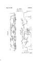
- Figure 4 is a longitudinal view of the new articulated locomotive fitted with the pump and the required pipings for circulation of -water within the water pipings forming a part .of the auxiliary boiler.
- Fig. 5 is a longitudinal sectional view of the new articulated locomotive composed of two units, unit D carryin the boiler of evaporation which is fed wlth water at the heat of eva oration by the auxiliary boiler carried by tie unit E;
- Fig. 6 is a diagrammatic view of the new articulated llocomotlve composed of three units, each unit DfE carrying an evaporatin boiler whichis fed by the two auxiliary ilers which are carried by the central unit C.
- FIGs 7, 8, 9 show in elevation the auxlliary boilers communicating withl the cooperating boiler and acting always under complete wate ⁇ filling, their highest point being lower than the level of the I:furnace roof of the steam l
- B the central driving unit embodying the evaporating boiler with metal furnace 3 the latter being in common with two opposed bodies 4, 5 containing each a number of fire tubes.
- the communication channels for the combustion gases with; the auxiliary boilers 6, 8 serving for heating the feed water of the steam producing or main boiler.
- the auxiliary boiler 6 is carried by the end unit A, whilst the auxiliary boiler 8 is carriedby the end unit C.
- Each auxiliary boiler 6, 8 contains ( Figures 1, 2, 3) in its lower portion steamtubes 29 and in the middle and upper portions smoke tubes 24 and water tubes 36.
- the water tubes 36 through which the circulating waterilows supplied by a pump. 42 (Fig. 4) .serve to heat water adapted for instance for heating the railway cars.
- The'l caps 37, 38 (Fig, 3) serve to insulate the water tubes 36 from the combustion gases.
- the boxes 33, 34 serve to insulate the steam tubes 29 from the combustion4 gases coming from the main boiler.
- the combustion gases issuing from the main boilerpass through'smoke tubes 24 (Figs. 1, 2, 3) of the auxiliary boilers 6, 7 and are discharged into the smoke rooms 7, 8.
- the surface of the smoke tubes 24, utilizing the available calories of the combustion gases of the main boiler raises the temperature of the water which is already pre-heated by the smoke tubes A29 up to the evaporation heat correspondin to the working pressureL of the main boller which latter, as shown in Fig-7 communicates with the auxiliary boiler ,6, 8 by means of link tubes 168, 169.-
- the water supply to the evaporation boiler is effected through 'the tubes 168.
- G indicates the uppermostin the main boiler is always higher than the highest point of the auxiliary oilers, 8.
- main boiler contacts-with'lthe.
- Water y whichhas already theevaporation heat.
- l the entire heated surface of the main boiler serves to transform the y water 'into steam while it is known that the locomotive boilers of the type used heretofore accomplish two functions, i. e.” the lower portion of surface of the said boilers serves to heat the Water up to the evaparation heat and only the remainder serves to transform water into steam.
- a main boiler carried by the center unit an auxiliaryvlboiler carried by each end unit, engine cylinders carried by the center unit, a re box associated with the main boiler, means for conducting the combustion gases from the fire-box through the auxiliary boilers, means for conducting the exhaust steam from the engine cylinders through the auxiliary boilers, the feed water for the main boilers being supplied by the auxiliary boilers and the combustion gases and exhaust steam for the center unit being utilizedto heat the feed Water for the main boiler up to the evaporation temperature existing in the main boiler'vvhereby the entire heating surface ofthe main boiler is utilized solely for converting the Water heated to evaporation temperature in the auxiliary boilers into steam.
- a locomotive as claimed in claim 1 characterized by the provision of a re box including a top Wall located above the auxiliary boilers whereby the latter may be always filled with Water at the same pressure existing in the main boiler.
- a locomotive as claimed in claim l characterized by the provision of Water tubes arranged in theauxiliary boilers adapted to supply heated Water for heating purposes.
Description
ug 8, A. FRANCO STEAM LocoMoTIfE Filed Feb. 25, 1925 4 Sheets-Sheet 8 h 6 q v VIN. 1h n M f r; f rn H .l Tm f V f f f f. nu s .ltkmw Imm- WW; 4 M w El ..-INN -4---. l jv #NQ uw xw ...WHW una i l. r
A FRANCO STEAM LOCOMOTIVE Flled Feb 25, 1925 gra -qg l .WANN
4 Sheets-Shee A. FRANCO STEAM LOCOMOTIVE Filed Feb. 25,. 1925 Aug. 28, 1923. 1,682,006
' A.FRANCO STEAM LOCOMOTIVE Filed Feb. 25, 1925 4 Sheets-Sheet Q a* *q I Patented Aug. 28, 1.928. Y,
uru'rrznA STATESPATENT' OFFICE.
F MILAN, ITALY.
STEAM LOCOMOTIVE.
Application led February 25, 1925, Serial ANo. 11,585, and in Italy February 25,1924.
l .new articulated locomotive composed of three driving units. The middle unit bears the evaporating boiler, whilst both end units each producer or main boiler.
carry an auxiliary boiler communicating with the main boiler, each 'auxiliary boiler supplying water to the main boiler at the temperature of evaporation.
Fig. 2 is a cross section and Fig. 3 an enlarged longitudinal'section of the auxiliary boiler. Figure 4 is a longitudinal view of the new articulated locomotive fitted with the pump and the required pipings for circulation of -water within the water pipings forming a part .of the auxiliary boiler.
- Fig. 5 is a longitudinal sectional view of the new articulated locomotive composed of two units, unit D carryin the boiler of evaporation which is fed wlth water at the heat of eva oration by the auxiliary boiler carried by tie unit E; Fig. 6 is a diagrammatic view of the new articulated llocomotlve composed of three units, each unit DfE carrying an evaporatin boiler whichis fed by the two auxiliary ilers which are carried by the central unit C.
Figures 7, 8, 9 show in elevation the auxlliary boilers communicating withl the cooperating boiler and acting always under complete wate` filling, their highest point being lower than the level of the I:furnace roof of the steam l In Figure 1 is shown at B the central driving unit embodying the evaporating boiler with metal furnace 3 the latter being in common with two opposed bodies 4, 5 containing each a number of fire tubes. At 12 are shown the communication channels for the combustion gases with; the auxiliary boilers 6, 8 serving for heating the feed water of the steam producing or main boiler.
The auxiliary boiler 6 is carried by the end unit A, whilst the auxiliary boiler 8 is carriedby the end unit C.
- Each auxiliary boiler 6, 8 contains (Figures 1, 2, 3) in its lower portion steamtubes 29 and in the middle and upper portions smoke tubes 24 and water tubes 36.
v The water tubes 36 through which the circulating waterilows supplied by a pump. 42 (Fig. 4) .serve to heat water adapted for instance for heating the railway cars. The'l caps 37, 38 (Fig, 3) serve to insulate the water tubes 36 from the combustion gases.
The boxes 33, 34 (Figs. 1, 3) serve to insulate the steam tubes 29 from the combustion4 gases coming from the main boiler.
Into the boxes 34 is discharged the exhaust steam from the vdriving cylinders E placed on the central unit B. The exhaust steam passing through the steam pipes 29 heats to a certain temperature (148. F.) the Water in the lower portion of the auxiliary boilers 6, 8 which latter, as shown -in Figure 7 'are fed through tubes 167 by pumps 164, drawingl the water from containers 165.
The combustion gases issuing from the main boilerpass through'smoke tubes 24 (Figs. 1, 2, 3) of the auxiliary boilers 6, 7 and are discharged into the smoke rooms 7, 8. The surface of the smoke tubes 24, utilizing the available calories of the combustion gases of the main boiler raises the temperature of the water which is already pre-heated by the smoke tubes A29 up to the evaporation heat correspondin to the working pressureL of the main boller which latter, as shown in Fig-7 communicates with the auxiliary boiler ,6, 8 by means of link tubes 168, 169.- The water supply to the evaporation boiler is effected through 'the tubes 168.
In the Figure 1, G indicates the uppermostin the main boiler is always higher than the highest point of the auxiliary oilers, 8.
From the foregoing description it will be eseen:
(d) That the evaporation boiler is fed from the ,auxiliary boiler with water having an evaporation temperature correspondin to working pressure of thelsaidmain iler; therefore the entire heated surface of, the
main boiler contacts-with'lthe. Water y whichhas already theevaporation heat. l In otherwords the entire heated surface of the main boiler serves to transform the y water 'into steam while it is known that the locomotive boilers of the type used heretofore accomplish two functions, i. e." the lower portion of surface of the said boilers serves to heat the Water up to the evaparation heat and only the remainder serves to transform water into steam. J
(b) That the auxiliary boilers 6, 8 act a1- Aways under complete Water filling at the same'pressure as the main boiler and raise the water to the evaporation heat lcorresponding to the Working pressureA of the main boiler simultaneously utilizing the available calories of the exhaust steam and of the combustion ases which in /the usual locomotives' are disc arged into the surrounding atmoshere.
That' by heating of the water within the (c auxiliary boilers to a higher temperature by each end unit for heating the feed Water for the main boiler up to the evaporation' `temperature existingl in the main boiler wherebyv the entire heating surface of the main boiler is utilized solely for converting the .water heated to evaporation temperature in the auxiliary boilers into steam.
2. In a'locomotive, interconnected end and center driving units, a main boiler carried by the center unit, an auxiliaryvlboiler carried by each end unit, engine cylinders carried by the center unit, a re box associated with the main boiler, means for conducting the combustion gases from the fire-box through the auxiliary boilers, means for conducting the exhaust steam from the engine cylinders through the auxiliary boilers, the feed water for the main boilers being supplied by the auxiliary boilers and the combustion gases and exhaust steam for the center unit being utilizedto heat the feed Water for the main boiler up to the evaporation temperature existing in the main boiler'vvhereby the entire heating surface ofthe main boiler is utilized solely for converting the Water heated to evaporation temperature in the auxiliary boilers into steam.
3. A locomotive as claimed in claim 1 characterized by the provision of a re box including a top Wall located above the auxiliary boilers whereby the latter may be always filled with Water at the same pressure existing in the main boiler.
4. A locomotive as claimed in claim l characterized by the provision of Water tubes arranged in theauxiliary boilers adapted to supply heated Water for heating purposes.
5; In a locomotive, interconnected end and center driving units, a plurality of main boilers on the center unit, and auxiliary boilers on the end units for heating the feed water for the main boiler up to the evaporation temperature existing in the main boiler.
ATTILIO FRANCO.
Applications Claiming Priority (1)
| Application Number | Priority Date | Filing Date | Title |
|---|---|---|---|
| IT1682006X | 1924-02-25 |
Publications (1)
| Publication Number | Publication Date |
|---|---|
| US1682006A true US1682006A (en) | 1928-08-28 |
Family
ID=11434463
Family Applications (1)
| Application Number | Title | Priority Date | Filing Date |
|---|---|---|---|
| US11585A Expired - Lifetime US1682006A (en) | 1924-02-25 | 1925-02-25 | Steam locomotive |
Country Status (1)
| Country | Link |
|---|---|
| US (1) | US1682006A (en) |
-
1925
- 1925-02-25 US US11585A patent/US1682006A/en not_active Expired - Lifetime
Similar Documents
| Publication | Publication Date | Title |
|---|---|---|
| US1682006A (en) | Steam locomotive | |
| US1555435A (en) | Feed-water heater | |
| US1345231A (en) | Steam-boiler | |
| US571762A (en) | Generator | |
| US1301156A (en) | Feed-water apparatus. | |
| US1865556A (en) | Tank car heater | |
| US409033A (en) | Smoke-box for locomotives | |
| US2068751A (en) | Locomotive | |
| US1798550A (en) | Automotive steam generator | |
| US1340074A (en) | Superheater | |
| US1973802A (en) | Locomotive steam boiler | |
| US1836747A (en) | Locomotive | |
| US1802125A (en) | Feed-water-heating device | |
| US1864310A (en) | Steam boiler | |
| US2018709A (en) | Boiler construction | |
| SU14866A1 (en) | Articulated steam locomotive | |
| US1743451A (en) | High-pressure steam boiler plant with generation of steam by indirect heating | |
| US1463250A (en) | Locomotive boiler | |
| US460347A (en) | baird | |
| US1788520A (en) | Process and apparatus for producing steam by indirect heating | |
| US2391491A (en) | Regenerative gas heater | |
| US1342544A (en) | Device for the recuperation of available heat on steam-locomotives provided with surface condensers | |
| US1708255A (en) | Locomotive boiler | |
| US1013771A (en) | Locomotive. | |
| GB121496A (en) | Improvements in or relating to Coal-distilling Apparatus. |