US167883A - Improvement in exhaust-pipes for locomotives - Google Patents
Improvement in exhaust-pipes for locomotives Download PDFInfo
- Publication number
- US167883A US167883A US167883DA US167883A US 167883 A US167883 A US 167883A US 167883D A US167883D A US 167883DA US 167883 A US167883 A US 167883A
- Authority
- US
- United States
- Prior art keywords
- pipes
- exhaust
- escape
- improvement
- pipe
- Prior art date
- Legal status (The legal status is an assumption and is not a legal conclusion. Google has not performed a legal analysis and makes no representation as to the accuracy of the status listed.)
- Expired - Lifetime
Links
- 230000003137 locomotive effect Effects 0.000 title description 5
- 241000220010 Rhode Species 0.000 description 2
- 241000723554 Pontia occidentalis Species 0.000 description 1
- 238000005266 casting Methods 0.000 description 1
- 238000010276 construction Methods 0.000 description 1
- 230000008602 contraction Effects 0.000 description 1
Images
Classifications
-
- F—MECHANICAL ENGINEERING; LIGHTING; HEATING; WEAPONS; BLASTING
- F23—COMBUSTION APPARATUS; COMBUSTION PROCESSES
- F23L—SUPPLYING AIR OR NON-COMBUSTIBLE LIQUIDS OR GASES TO COMBUSTION APPARATUS IN GENERAL ; VALVES OR DAMPERS SPECIALLY ADAPTED FOR CONTROLLING AIR SUPPLY OR DRAUGHT IN COMBUSTION APPARATUS; INDUCING DRAUGHT IN COMBUSTION APPARATUS; TOPS FOR CHIMNEYS OR VENTILATING SHAFTS; TERMINALS FOR FLUES
- F23L17/00—Inducing draught; Tops for chimneys or ventilating shafts; Terminals for flues
- F23L17/16—Induction apparatus, e.g. steam jet, acting on combustion products beyond the fire
Definitions
- JAMES J. FARMER, of the city of Buffalo, in the State of Rhode Island, have invented an Improvement in Exhaust-Pipes for Locomotives and other similar steam-engines, of which the following is a specification
- the object of my invention is to obviate or greatly diminish the back pressure (so called) upon the piston that results from the obstruction to the escape of the exhaust steam occasioned by the contraction of the nozzle or tip of the exhaust-pipe.
- the ordinary exhaust-pipe is cast in two parts, the main pipe constituti g one, and the detachable nozzle or tip the other part.
- the main pipe I construct with a double wall, and with an annular space or chamber between the two walls open at the top and closed at the bottom. I make one or more openings in the outer wall, at or near the bottom of the chamber, connecting with escape-pipes that extend alongside the exhaust-pipe, within the smoke-stack, to a height equal to the top of the nozzle when in place.
- the width of the space between the two walls of the pipe I make about one-half inch, and the diameter of the escape-pipes, of which I prefer two to each chamber, I make about one inch.
- the nozzle, when in place, is attached to the outer Wall of the main pipe.
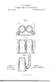
- Figure l is a horizontal section (showing two pipes united in the usual way on a locomotive, one for each cylinder) through the point where the escape-pipes connect withthe chambers.
- AA are the main exhaustpipes.
- O O are the annular spaces. or chambers between the two walls.
- E E are the openings from the chambers into the escapepipes, and D D are the escape-pipes.
- Fig. 2
- FIG. 3 is also a vertical section of a single exhaust-pipe, in which the same letters denote the same parts as in the other figures, and is intended to illustrate certain variations in construction hereinafter referred to.
- the open space or chamber between the walls of the exhaust-pipe may be enlarged by extending it downward to within such distance of the bottom of the pipe as will leave the casting of sufficient strength, or by extending upward the inner wall, as shown in Fig. 3.
- the escape-pipes may be carried up higher than the top of the nozzle, as shown in Fig. 3, or may be made to connect with the water-tank on the tender, and the steam they discharge utilized, but at present I regard these variations as inferior arrangements.
- the back pressure begins to operate at or about the point where the nozzle begins to contract, it causes a portion of the steam to overflow the inner wall of the main pipe into the annular-chamber, whence it finds an outlet by means of the escape-pipes described, and I find that neither the upward movement of the exhaust steam through the main pipe and nozzle, nor the blast, is unfavorabl y affected by the escape-pipesD D, while, on the other hand, the back pressure on the piston is very greatly relieved by the secondary means of escape my improvement affords to. the exhaust steam, and the power of the engine is increased.
Landscapes
- Engineering & Computer Science (AREA)
- Chemical & Material Sciences (AREA)
- Combustion & Propulsion (AREA)
- Mechanical Engineering (AREA)
- General Engineering & Computer Science (AREA)
- Plural Heterocyclic Compounds (AREA)
Description
1. C. FARMEB.
Exhaust-Pipe for Locomotives.
No. 167,883. Patented Seot.21.1875.
Wilnesses. fizvenlor.
N,FETERS, Fh'OTmLlTHQGRAPMER, WASHINGTON D c.
UNITED STATES PATENT OFFICE.
JAMES C. FARMER, OF PROVIDENCE, RHODE ISLAND, ASSIGNOR OF ONE- HALF HIS RIGHT TO JOHN W. WHITE, OF DEDHAM,MASSAOHUSETTS.
IMPROVEMENT IN EXHAUST-PIPES FOR LOCOMOTIVES.
Specification forming part of Letters Patent No- 167,8S3, dated September 21, 1875 application filed May 14, 1875.
To all whom it may concern Be it known that I, JAMES (J. FARMER, of the city of Providence, in the State of Rhode Island, have invented an Improvement in Exhaust-Pipes for Locomotives and other similar steam-engines, of which the following is a specification The object of my invention is to obviate or greatly diminish the back pressure (so called) upon the piston that results from the obstruction to the escape of the exhaust steam occasioned by the contraction of the nozzle or tip of the exhaust-pipe. This I accomplish by constructing the exhaustpipe with arelief chamher or chambers, into which the exhaust steam that fails to find a ready exit vertically through the nozzle may be deflected, and thence escape through openia gs in the chamber connected with suitable escape-pipes.
The ordinary exhaust-pipe is cast in two parts, the main pipe constituti g one, and the detachable nozzle or tip the other part. The main pipe I construct with a double wall, and with an annular space or chamber between the two walls open at the top and closed at the bottom. I make one or more openings in the outer wall, at or near the bottom of the chamber, connecting with escape-pipes that extend alongside the exhaust-pipe, within the smoke-stack, to a height equal to the top of the nozzle when in place. The width of the space between the two walls of the pipe I make about one-half inch, and the diameter of the escape-pipes, of which I prefer two to each chamber, I make about one inch. The nozzle, when in place, is attached to the outer Wall of the main pipe.
Figure l is a horizontal section (showing two pipes united in the usual way on a locomotive, one for each cylinder) through the point where the escape-pipes connect withthe chambers. AA are the main exhaustpipes. O O are the annular spaces. or chambers between the two walls. E E are the openings from the chambers into the escapepipes, and D D are the escape-pipes. Fig. 2
I is a vertical section of the same, in which A A are the main-pipes, B B are the detachable nozzles or tips in place, 0 O are the annular spaces or chambers between the two walls of the main pipes, and D D are the escape-pipes. Fig. 3 is also a vertical section of a single exhaust-pipe, in which the same letters denote the same parts as in the other figures, and is intended to illustrate certain variations in construction hereinafter referred to.
The open space or chamber between the walls of the exhaust-pipe may be enlarged by extending it downward to within such distance of the bottom of the pipe as will leave the casting of sufficient strength, or by extending upward the inner wall, as shown in Fig. 3. But I consider the arrangement most efficient when the two walls are of about the same height, as in Fig. 2. I consider a continuous chamber, annular in form, preferable, but not essential. The escape-pipes may be carried up higher than the top of the nozzle, as shown in Fig. 3, or may be made to connect with the water-tank on the tender, and the steam they discharge utilized, but at present I regard these variations as inferior arrangements.
In the application and use of my improvement, as the back pressure begins to operate at or about the point where the nozzle begins to contract, it causes a portion of the steam to overflow the inner wall of the main pipe into the annular-chamber, whence it finds an outlet by means of the escape-pipes described, and I find that neither the upward movement of the exhaust steam through the main pipe and nozzle, nor the blast, is unfavorabl y affected by the escape-pipesD D, while, on the other hand, the back pressure on the piston is very greatly relieved by the secondary means of escape my improvement affords to. the exhaust steam, and the power of the engine is increased.
I claim as my invention- An exhaust-pipe for locomotive and other similar engines, constructed with a double wall and intervening relief-chamber, as described, into which relief-chamber a portion. of the exhaust steam overflowing the inner wall may be deflected by the back pressure, and thence find an outlet by means of suitable escape-pipes at-or near the bottom of the chamber, substantially as and for the purpose hereinbefore set forth.
JAMES C. FARMER.
Witnesses:
J ON. F. BARRETT, W. F. WATSON.
Publications (1)
| Publication Number | Publication Date |
|---|---|
| US167883A true US167883A (en) | 1875-09-21 |
Family
ID=2237292
Family Applications (1)
| Application Number | Title | Priority Date | Filing Date |
|---|---|---|---|
| US167883D Expired - Lifetime US167883A (en) | Improvement in exhaust-pipes for locomotives |
Country Status (1)
| Country | Link |
|---|---|
| US (1) | US167883A (en) |
-
0
- US US167883D patent/US167883A/en not_active Expired - Lifetime
Similar Documents
| Publication | Publication Date | Title |
|---|---|---|
| US167883A (en) | Improvement in exhaust-pipes for locomotives | |
| US149270A (en) | Improvement in furnaces | |
| US186417A (en) | Improvement in exhaust-pipes for locomotives | |
| US505190A (en) | Exhaust for steam-engines | |
| US202144A (en) | Improvement in variable exhausts for locomotives | |
| US683658A (en) | Steam-locomotive. | |
| US458996A (en) | Means for regulating the draft in smoke-stacks | |
| US1185008A (en) | Locomotive. | |
| US166562A (en) | Improvement in exhaust-nozzles | |
| US569561A (en) | Cassius m | |
| US130759A (en) | Improvement in feed-water heaters for locomotives | |
| US198789A (en) | Improvement in variable exhausts for locomotives | |
| US1057062A (en) | Marine boiler. | |
| US1001075A (en) | Steam-superheating apparatus for locomotive-boilers. | |
| US1703052A (en) | Exhaust-nozzle tip for locomotives | |
| US426891A (en) | Condenser | |
| US498959A (en) | Smoke-consuming furnace | |
| US211099A (en) | Improvement in steam-boiler attachments | |
| US1348737A (en) | Steam-boiler ash-pan | |
| US1157060A (en) | Smoke-stack attachment. | |
| US204522A (en) | William f | |
| US713641A (en) | Exhaust mechanism. | |
| US6116A (en) | Improvement in spark and gas consumers | |
| US852735A (en) | Steam-dome. | |
| US162120A (en) | Improvement in steam-engine cylinders |