US1671663A - Liquid pump - Google Patents
Liquid pump Download PDFInfo
- Publication number
- US1671663A US1671663A US102232A US10223226A US1671663A US 1671663 A US1671663 A US 1671663A US 102232 A US102232 A US 102232A US 10223226 A US10223226 A US 10223226A US 1671663 A US1671663 A US 1671663A
- Authority
- US
- United States
- Prior art keywords
- coin
- receptacle
- spring
- detent
- parts
- Prior art date
- Legal status (The legal status is an assumption and is not a legal conclusion. Google has not performed a legal analysis and makes no representation as to the accuracy of the status listed.)
- Expired - Lifetime
Links
Images
Classifications
-
- G—PHYSICS
- G07—CHECKING-DEVICES
- G07F—COIN-FREED OR LIKE APPARATUS
- G07F5/00—Coin-actuated mechanisms; Interlocks
- G07F5/02—Coin-actuated mechanisms; Interlocks actuated mechanically by coins, e.g. by a single coin
Definitions
- adjusthle to vary the throiv of the Another object of thel invention is to prop'lm'p plunger 9) in a redini slot 7 "formed vide novel means whereby a lead slug or in a rotar, member 6 carried hy ashaft 4,
- ether article having a transverse bending, journled 1n the support 1, and operted by strength Whih is less than ⁇ thatfoi a coin crank 5, or otherwise.
- the rotiiifinenibei- 65 or standard mintage, cannot be used to oper- 6 may be a ratchet Wheel, engaged a back ate the device.
- stop pawvl that is pivotally mounted at 15 It is within the ro'vin-ce of the disclosure loon the support '1.x Tlhe rotary member o to improve general y end to enhance the util- 'crrles opener or spreeder for the coin reity of devices Vof that type to which the inc'eptrcle (hereiiiiftei" ⁇ described) find the 70 vention appertains; V y i l f Opener or spreader, marked by the nume'rl
- the invention resides in the ⁇ comloishafti.
- the support 1 ⁇ is provided with spaced invention herein disclosed, may he .milde hearings 19" thereon is fnlcrurned a.y detent,
- Liquid issupplied to the tanlr through a "mit 2BV on linger and pipe 3, leading ulruvafrdly ⁇ through the supthe xbrawfcket., 'lhere ⁇ 1s an adjusting ⁇ nut ⁇ or port 1, andfrom the tank 1Q, liquid is carnt2u9 ⁇ on tli'etinglerQ, lboi'fe VarinA p ried to ⁇ the point of use or delivery through -V cfmpiession spring 30 srrou'nds a 100 ahose 1 1.
- the spring 31 embodies two depending side portions 32 which constitute part of the coin receptacle.
- the coin receptacle is completed by oppositely disposed angle members 34-34 and 33-33, which are secured to the side portions 32 of the spring 31 that forms one arm of the bell crank detent.
- the members 34 are spaced at their inner edges, to form a slot 35.
- adjusting device 41 connects the parts 32, in that it is threaded into one of them, and bears upon the other, the said members 32 tending to spring inwardly toward each other.
- the machine vembodies a thrust member which is marked generally by the numeral 42 in Figure 3, the thrust member being in the form of a push pin 43 having a head 44, a compressionA spring 45 being interposed between the head 44 anda part of the support l, the push pin 43 being slidable in the support, and outward movement of the push pin, responsive to the spring 45, being limited by a shoulder 46 on the push pin, which engages the support or casing 1.
- the pu-sh vpin 43 is adaptedvto be advanced with respect to the opening 35 that exists between the parts 34 of the coin receptacle, so ⁇ that the .inner end ofthe push pin may engage with a coin 47 held by the toe 40 in the passage 48 that exists between the parts 34 and of the coin receptacle.
- the push pin 44 is supplied at its inner end with oppositely projecting fins 49.
- the ordinary operation of the ⁇ machine is as follows The operator puts a coin in the slot 53, and the coinltraverses the chute 51 and passes through the slot 50, into the passage 48, where the coin is held, by the toe 4l), in the path of the push in 43.
- the push pin 43 is thrust inwar ly, enraging the coin, and tilting the bell crank ever or detent on its fulcrum 23 ⁇ until the inner end of the arm 21 is out of the path of the shoulder 18 on the rotary member 6.
- the rotary member 6 then can be turned, by means of the crank 5 or its equivalent, to operate the plunger 9 and forcea measured quantity of liquid up into the tank ⁇ l0 through the pipe Vlien the rotary mein ber 6 is turned, the opener or spreader 17 on the rotary member 6 passes between the inclined edges 39 of the coin receptacle, and opens it, the parts 32 of the vspring 31 yielding for this purpose.
- the coin receptacle thus is opened, the coin 47 is permitted to drop into a drawer 55er other receptacle in the support 1, and when the coin drops out of the coin receptacle, the coin receptacle no longer is under the control of the.
- the spring 30 exerts a strong pressure on the arm 21 of the bell crank detent, and this pressure may be adjusted by means of the nut 29.
- the pressure exerted by the spring 30 is strong enough so that, in order to over- ⁇ come it, a coin of standard mintage must be interposed between the inner end of the push pin Li3 and the parts 37. ⁇ If a Weak article occupies the place of the coin 47 in Figure 2, for instance, a lead ⁇ slug,the slugr will not be strong enough ⁇ to stand the pres .sure from the push pin Zlthat is necày to overcome the action of the spring 30, and the result is that the slug bends under the action of the push pin and slips olf the parts 37 without causing the bell crank detent to be operated and the arm 2l thereof lifted out of the path of the shoulder 1S.
- a rotary member an opener on the rotary member and including a cam, a movable detent engaging the opener to hold the rotary member .againstrotation, a coin receptacle carried by the detent and comprising separable parts, means for discharging a coin between said parts of the receptacle, mechanism under the control of anoperator for engaging a coin in the receptacle, thereby to ⁇ move the detent out of holding engagement with the opener, and means for ⁇ rotating the rotatable member to cause the cam to move the detent and the receptacle far enough so that said mechanism will no longer cooperate with a coin in the receptacle, the opener coacting with the separable parts of the receptacle, when the rotary member is rotated, to open the receptacle and release the coin.
- a rotary member an opener on the rotary member and including a cam, a detent lever ful-v ⁇ crumed for swinging movement, one end of the lever engaging the opener to hold the rotary member against rotation, a coin receptacle forming the other end of the lever and con'iprising separable parts,k means for discharging a coin between said parts of the receptacle, a push pin mounted for siding movement and under the control of an operator to engage a coin in the receptacle, thereby to move the rst-specilied end of the lever out of holding engagement with the opener, and means for rotating the rotatable member to cause the cam to move the lever far enough so that the push pin will no longer cooperate with a coin in the receptacle, the opener cooperating with the separable parts of the receptacle, when the rotary member is rotated, thereby to open the receptacle and release the coin.
- a device of the class described a bell crank detent and a fulcrum therefor, a rotary member having a shoulder, a fixed stop, spring means for holding one arm ofthe bell crank detent on the stop and in the pat-h of the shoulder on the rotary member, the other arm of the detent being in the form of a coin receptacle, means forconducting a coin into the coin receptacle, a plunger, and
Landscapes
- Physics & Mathematics (AREA)
- General Physics & Mathematics (AREA)
- Control Of Vending Devices And Auxiliary Devices For Vending Devices (AREA)
Description
May 29,v 1928. 1,671,663
Y w. s. AUSHERMAN Er AL LIQUID PUMP Filed April 15, 192e @L5 J4 Ef ya@ F 522% ventoz attowum,
mmdwfwfm?" ZZAZwZe/'m/w Patented May 29, 192s. p `1,671,663
unirse 'grues rimani wIiLiAiis. Ausiinniithn, or LMAGE, Ann I'iAnn s. Ansirniniin, oiAiiInNE;
KANSAS.
LIQUD iir.
p v Appnatmn ined Apre 15, ieee. sensi no. iaze.
:Phe device forming the subject metter ot relates to coin-control: sind it isknown this application 1s a coincokntrol for a vendthatp coin-controll'ed` mechanism carlno't'be 55 ing machine, and the inventionaims to procharncterized patentahly` pump pdetils.` vide novel means whereby the coin 1s per- Let 1t sutlice,l`tlie, to stette that the' umping l 5 niitted to drop out ofthe coin receptacle remechanism embodies the plunger Where# `gerdless ofthe pressure exerted on the thrust unto a pitman 12 is pivoted et 14, the lower liieinher which operates the machine throng end oi' the pitlnan `being pivote'dto a Wrist 60 the instrumentality of the coin. pin 8, adjusthle (to vary the throiv of the Another object of thel invention is to prop'lm'p plunger 9) in a redini slot 7 "formed vide novel means whereby a lead slug or in a rotar, member 6 carried hy ashaft 4,
ether article having a transverse bending, journled 1n the support 1, and operted by strength Whih is less than `thatfoi a coin crank 5, or otherwise. The rotiiifinenibei- 65 or standard mintage, cannot be used to oper- 6 may be a ratchet Wheel, engaged a back ate the device. stop pawvl that is pivotally mounted at 15 It is within the ro'vin-ce of the disclosure loon the support '1.x Tlhe rotary member o to improve general y end to enhance the util- 'crrles opener or spreeder for the coin reity of devices Vof that type to which the inc'eptrcle (hereiiiiftei"` described) find the 70 vention appertains; V y i l f Opener or spreader, marked by the nume'rl With the foregoing and other objects in 117,lras a circumferential earn `edge 27 which vieiv Which willy pper the description is d'ispos'etl eccentric/ally yelfith respect t the proceeds, the invention resides in the `comloishafti. l Oife v`end of the merriher 17, Instrkcd nation end arringementl of parts and in the the numeral `18, formen shoulder which 75 details oi construction hereinafter described is' engitged with a detent,I` next to he deand claimed, it being understood that scribed.
5 changes in the precise vembed-inrant or the The support 1 `is provided with spaced invention herein disclosed, may he .milde hearings 19" thereon is fnlcrurned a.y detent,
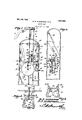
Within the scope of `what is climed, Without iii the forni of e.` bell' crank. The bell crank 80 departing from the spirit of the invention. detnt embodies an arm 21` held by a cap In the accompanying drawings piece 2 tofswing on a fshat 23 `nnounted Figure 1` shows in verticallongitudinnl inthe jeziriri'gs;19.l Une end of the arm 21 section, a device constriicted `in accordance of the hell c'riil detent lies normally in the With the invention, parts being in elevation; pfzith ofthe opeiiet or spreader 17, and en- 85 Figure 2 is a section onthe line 2-2 of g'ges-' thewshoulder 18. wnvvard Figure 1; p swinging ihov'einent of the arm 2 is limited Figure 3 is asection on' thel'ine 3-3 of b v a stop 24, such s a pin or the like,
Figure `2; y p the spring means Figure 4 is a section on the line 4-4 of is provided" for holding doivn the arm 21 90 Figure Q p orf the stop 2li, the said neans including a In carrying outvthe invention, there 1s de' ending iinlger25 onfwhich `the arn1`21 provided a support or casing 1, equipped at strings, the `Iingerl Being mounted at its its top with a "guide 2. Above the support 1 upper end infn bracket 36 oli the support 1. is located a tank 10, which may be mounted The finger 25 lis thr'eded for djustnient 95 oii a bracketQO, `carried by the support 1. into the brfaekett and isrheld in placev Liquid issupplied to the tanlr through a "mit 2BV on linger and pipe 3, leading ulruvafrdly` through the supthe xbrawfcket., 'lhere `1s an adjusting `nut` or port 1, andfrom the tank 1Q, liquid is carnt2u9`on tli'etinglerQ, lboi'fe VarinA p ried to `the point of use or delivery through -V cfmpiession spring 30 srrou'nds a 100 ahose 1 1. Theliquidnfhich the tankl 1'() 'ref portion finger 25, one end of "the ceives, is forced the pipe 3 by a spring" gaging the'adjiisting nntn2`99 pumping mechanism ivhich `includes [a the other "endof the'spring heering on "t `e plunger 9, lnountednto reciprocate in the erm enf, l p y guid, 2- `The, .umpinee'nechaeise@Sg 120i Th .Sfit e? bell Creek.. lre" yiels. 1 ,shown in 4great etal, becausethis-invention al U-hpedspring 33tlie"crottnot which is secured to the arm 21 at a point adjacent to the shaft 23, so that the spring 31, and parts carried thereby, form the other arm of the bell crank lever or detent. The spring 31 embodies two depending side portions 32 which constitute part of the coin receptacle. The coin receptacle is completed by oppositely disposed angle members 34-34 and 33-33, which are secured to the side portions 32 of the spring 31 that forms one arm of the bell crank detent. The members 34 are spaced at their inner edges, to form a slot 35. rlhe lower parts of the inwardly projecting flanges of the angle members 33 arecut away, as at 36, leaving only those parts 37 of theangle men'ibers 33 which bear against the side portions 32 of a spring 31 directly, as shown in Figure 3. ling plates 38 are secured to the side portions 32 of the spring 31, and the inner longitudinal edges of the wing plates 38 converge, as shown best at 39 in Figure 2. One of the side portions 32 of the spring 31 is turned inwardly at its lower end, to fashion a coin retaining toe 40, best shown in Figure 2. An adjusting device, such as a screw 41, connects the side portions 32 of the spring 31, so as to vary the distance between the parts 32, to enable the vmachine to be altered for coins of different diameters, and
vstill have the coin held by the toe 40. The
adjusting device 41 connects the parts 32, in that it is threaded into one of them, and bears upon the other, the said members 32 tending to spring inwardly toward each other.
The machine vembodies a thrust member which is marked generally by the numeral 42 in Figure 3, the thrust member being in the form of a push pin 43 having a head 44, a compressionA spring 45 being interposed between the head 44 anda part of the support l, the push pin 43 being slidable in the support, and outward movement of the push pin, responsive to the spring 45, being limited by a shoulder 46 on the push pin, which engages the support or casing 1. The pu-sh vpin 43 is adaptedvto be advanced with respect to the opening 35 that exists between the parts 34 of the coin receptacle, so `that the .inner end ofthe push pin may engage with a coin 47 held by the toe 40 in the passage 48 that exists between the parts 34 and of the coin receptacle. The push pin 44 is supplied at its inner end with oppositely projecting fins 49. There is a slot 50 in one of the side portions 32 of the spring 31, and this slot lets the coin into the passage 48, the coin being adapted to traverse a chute 51, carried by the support 1 and having a hopper 52 at its upper end, into which the coin finds its way through a slot 53 in the support or casing 1, a magnet 54 being disposed adjacent to the hopper or intake end 52 of the chute 51, to segregate slugs of magnetic metal, before they have a chance to get down into the machine and facilitate the unlawful working of it.
The ordinary operation of the `machine is as follows The operator puts a coin in the slot 53, and the coinltraverses the chute 51 and passes through the slot 50, into the passage 48, where the coin is held, by the toe 4l), in the path of the push in 43. The push pin 43 is thrust inwar ly, enraging the coin, and tilting the bell crank ever or detent on its fulcrum 23` until the inner end of the arm 21 is out of the path of the shoulder 18 on the rotary member 6. 1 The rotary member 6 then can be turned, by means of the crank 5 or its equivalent, to operate the plunger 9 and forcea measured quantity of liquid up into the tank `l0 through the pipe Vlien the rotary mein ber 6 is turned, the opener or spreader 17 on the rotary member 6 passes between the inclined edges 39 of the coin receptacle, and opens it, the parts 32 of the vspring 31 yielding for this purpose. `When the coin receptacle thus is opened, the coin 47 is permitted to drop into a drawer 55er other receptacle in the support 1, and when the coin drops out of the coin receptacle, the coin receptacle no longer is under the control of the. push )in 43, but goes back, under the impulse of the spring 30, into the position of Figure 1, so that the inner end of the arm 21 is in the path of the Shoulder 18, thereby preventing the operator from turning the shaft 4 Vand pumping liquid indefinitely. i t
So faras the description of the operation above set forth is concerned, it would be possible for the operator,r to push in the pin 43, keep a steady pressure on the coin 47,'hold the coin in place notwithstanding the fact that the coin receptacle had been spread apart laterally by the action of the member 17, and obtain as much lquidas he wished, by depositing a single coin.l Observe, however, that this cannot take place` because the eccentric edge 27 of the member 17 cooperates with the undcrsurfaee of: thc arm 21, as the part 6 is rotated. thereby to tilt the belt crank gradually into such aV position that the coin 47, in the position shown in Figure 2. spaced from the iuner end of the push pin 43. and, therefore, 'cannot he held in place by the push pin, for the unlawful and improper purpose of obtaining more liquid than is paid for by the deposit of a single coin. i
The spring 30 exerts a strong pressure on the arm 21 of the bell crank detent, and this pressure may be adjusted by means of the nut 29. The pressure exerted by the spring 30 is strong enough so that, in order to over-` come it, a coin of standard mintage must be interposed between the inner end of the push pin Li3 and the parts 37.` If a Weak article occupies the place of the coin 47 in Figure 2, for instance, a lead `slug,the slugr will not be strong enough `to stand the pres .sure from the push pin Zlthat is necessaiy to overcome the action of the spring 30, and the result is that the slug bends under the action of the push pin and slips olf the parts 37 without causing the bell crank detent to be operated and the arm 2l thereof lifted out of the path of the shoulder 1S. The reason for cutting away the lower portions of the inwardly extended 'flanges of 'the members is to leave a wide space between the parts 3'?, as shown in Figure 3, it beingunnecessary, therefore, to bend a lead slug much, by the action of the push pin 43, before the slug slips off the parts 37, it being obvious that if the slug had to be pushed through the narrow slot that exists between the parts 33 in Figure t, it would be necessary to double the slug until it was almost flattened together. A little bending of the slug, however, will permit it to slip off the narrow parts 37, under the action of the push pin a3.
It may happen that a person will drop a ring-shaped washer into the machine. Then, the push pin 43 will saw bacl; and forth through the hole in the `washer, without operating the machine, but the Washer will hang in place, in the position shown by the coin 47 in Figure 2, and if a legitimate purchaser deposits a coin, the coin will come to rest on top of the washer, ther pin will continue to work back and forth through the washer, and the person who has deposited the coin will get nothing in return for it. The foregoing operation presupposes that the pin 43 is devoid of the fins 49, but because the fins 49 are supplied, they will enengage a washer, when the push pin 43 is thrust inwardly, and pass on the` washer., through the machine, thereby preventing the washer from hanging in the position shown at Il? in Figure 2, and holding upl the further operation of the device.
That is claimed is l. In a device of the class described, a rotary member, an opener on the rotary member and including a cam, a movable detent engaging the opener to hold the rotary member .againstrotation, a coin receptacle carried by the detent and comprising separable parts, means for discharging a coin between said parts of the receptacle, mechanism under the control of anoperator for engaging a coin in the receptacle, thereby to `move the detent out of holding engagement with the opener, and means for` rotating the rotatable member to cause the cam to move the detent and the receptacle far enough so that said mechanism will no longer cooperate with a coin in the receptacle, the opener coacting with the separable parts of the receptacle, when the rotary member is rotated, to open the receptacle and release the coin.
2. In a device. of the vclass described,V a rotary member, an opener on the rotary member and including a cam, a detent lever ful-v `crumed for swinging movement, one end of the lever engaging the opener to hold the rotary member against rotation, a coin receptacle forming the other end of the lever and con'iprising separable parts,k means for discharging a coin between said parts of the receptacle, a push pin mounted for siding movement and under the control of an operator to engage a coin in the receptacle, thereby to move the rst-specilied end of the lever out of holding engagement with the opener, and means for rotating the rotatable member to cause the cam to move the lever far enough so that the push pin will no longer cooperate with a coin in the receptacle, the opener cooperating with the separable parts of the receptacle, when the rotary member is rotated, thereby to open the receptacle and release the coin.
ln a device of the class described, a bell crank detent and a fulcrum therefor, a rotary member having a shoulder, a fixed stop, spring means for holding one arm ofthe bell crank detent on the stop and in the pat-h of the shoulder on the rotary member, the other arm of the detent being in the form of a coin receptacle, means forconducting a coin into the coin receptacle, a plunger, and
`means for so mounting the plunger that it will engage a coin in the receptacle, tilt the detent against the action of the sprin n'ieans, and move the first-specified arm o the detent out of the path of the shoulder; and mechanism for adjusting the aforesaid spring means to enable it to hold the detent against swinging movementresponsive to the thrust of the plunger, when the coin in the receptacle has a bending strength that is less than the bending strength of a coin of standard mintage.
In testimony that we claim the foregoing as our own, we have hereto affixed our signatures.
` VILLIAM S. AUSHERMAN` HARRY S. AUSHERMAN.
Priority Applications (1)
| Application Number | Priority Date | Filing Date | Title |
|---|---|---|---|
| US102232A US1671663A (en) | 1926-04-15 | 1926-04-15 | Liquid pump |
Applications Claiming Priority (1)
| Application Number | Priority Date | Filing Date | Title |
|---|---|---|---|
| US102232A US1671663A (en) | 1926-04-15 | 1926-04-15 | Liquid pump |
Publications (1)
| Publication Number | Publication Date |
|---|---|
| US1671663A true US1671663A (en) | 1928-05-29 |
Family
ID=22288811
Family Applications (1)
| Application Number | Title | Priority Date | Filing Date |
|---|---|---|---|
| US102232A Expired - Lifetime US1671663A (en) | 1926-04-15 | 1926-04-15 | Liquid pump |
Country Status (1)
| Country | Link |
|---|---|
| US (1) | US1671663A (en) |
-
1926
- 1926-04-15 US US102232A patent/US1671663A/en not_active Expired - Lifetime
Similar Documents
| Publication | Publication Date | Title |
|---|---|---|
| US1355583A (en) | Vending-machine | |
| US1671663A (en) | Liquid pump | |
| US1165907A (en) | Sugar-bowl. | |
| US1217616A (en) | Vending-machine. | |
| US1733195A (en) | Pump lock for gasoline-vending machines | |
| US1057322A (en) | Slot-machine. | |
| US955718A (en) | Fruit-selling slot-machine. | |
| US1447511A (en) | Liquid dispensing apparatus | |
| US2675008A (en) | Coin counting machine | |
| US751276A (en) | Vending-machine | |
| US1500177A (en) | Automatic liquid pump | |
| US1209758A (en) | Vending-machine. | |
| US373585A (en) | And fbank bate | |
| US6243A (en) | Improvement in type-casting machines | |
| US547250A (en) | Tube loader foe button setting machines | |
| US643683A (en) | Measuring vessel. | |
| US1695436A (en) | Gasoline-dispensing device | |
| US496749A (en) | Coin-operated mechanism | |
| US762909A (en) | Coin-operated mechanism for vending-machines. | |
| US1946372A (en) | Combined filling station pump and vending machine | |
| US1368721A (en) | Machine for grading soles, &c. | |
| US937092A (en) | Combined cigar-cutter and match-vending machine. | |
| US2079832A (en) | Coin controlled mechanism | |
| US1197220A (en) | Perfume-vending machine. | |
| US1287373A (en) | Dispensing match-box. |