US1664053A - Combination stop action for organs - Google Patents
Combination stop action for organs Download PDFInfo
- Publication number
- US1664053A US1664053A US739811A US73981124A US1664053A US 1664053 A US1664053 A US 1664053A US 739811 A US739811 A US 739811A US 73981124 A US73981124 A US 73981124A US 1664053 A US1664053 A US 1664053A
- Authority
- US
- United States
- Prior art keywords
- switch
- trace
- stop
- combination
- ancl
- Prior art date
- Legal status (The legal status is an assumption and is not a legal conclusion. Google has not performed a legal analysis and makes no representation as to the accuracy of the status listed.)
- Expired - Lifetime
Links
Images


Classifications
-
- G—PHYSICS
- G10—MUSICAL INSTRUMENTS; ACOUSTICS
- G10B—ORGANS, HARMONIUMS OR SIMILAR WIND MUSICAL INSTRUMENTS WITH ASSOCIATED BLOWING APPARATUS
- G10B3/00—Details or accessories
- G10B3/10—Actions, e.g. key actions, couplers or stops
Definitions
- the invention relates t combination st0p actions -f01 organs. 1
- An object of the present invention is to provide an electri0ally controlled mechanism f01 simultaneously 1noving a predetermined arrangement 0f organ stops t0 either operative 01 inoperative position, and also to permit independent actuation of any organ stop within 0 3 With0ut the desired group W1thout changing the group arrangement,
- the mechanism c an be disposed at any suitable location distant from the console and thereby capable 0f incorporating any desired number 0f combinations and permitting flexibility in installation; it being then possible t0 manufacture consoles in standard sizes reg'aldless 0I" the number 0'f combinations incorporated and to readily install the 3h mechanism in existing organs.
- t0 provide a combination stop action mechanism including movable members carrying tw0- position switches 01 a nove1 design f01 c0ntrolling circuits admiting sops t0 a combination 01 exclucling them therefrom and means f01 s?multaneously setting a plurality 0ft sWitches to either of their desired positions.
- a further objecs of the invention is 00 provide a coznbination stop action in which swiiches 011 the console unde1 the control 0f the organist serve both to bring 011 combinations 211d t0 setcombinations, an additio'nal common control switch being used in conjunction for performing t-he 1atter opera ti0n
- a further objec of the invention is to periect details of conscruction generally to provide for simplicity and compactness.
- the invention further consists in the sev e1a1 u?eatures hereinafter set forth andmore particularly defined by claims atthe conclusion hereof.
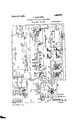
- Fig. 1 is a dlagrammatic perspective view 0f a StOP Alpp1ication filed. September 2 5, 1924. Seria1 N0. 739,811.
- Fig. 2 is a vertical seictional view takten onfl the line 22 0f Fig. 1 and including tracr.
- Fig. 3 is a view similar t0 Fig. 2, but parts being broken away to show the setting elemeniis and combination setting circuits being included;
- Fig. 4 is a vertical sec tional view 011 the line 44 of Fig. l;
- Fig. 5 is a fragmentary detztil vieW 0f a trace bar and its switch elements
- Fig. 6 is a rear end view 0f a tracebap
- Fig. 7 is a section al view taken onthe line 77 of Fig. 5;
- Fig. 8 is a detail elevation of one 0f the t1a'ce bar switch members.
- a pipe Organ ii1 cludes a number 0f stops and mez;ns f0r inde.pendent1y operating the same.
- the organ stops have noc been sh0wn in the drawi1igs, as they are 0f usual canstruc tion, such as the faken electropneumatically controlled tjrpe.
- Stop operating devices in the console may be 01 any type, but in the dmwings are shown t0 be stop keys 10 vvh1ch a1e p1vota'lly mounted fo1 111dependent rockmgmovement 011 the stationary horizontal shaft 11 in the usual manner, splings 12 serving to retain the stop keys 111 -the1r off and 0n positionS and the stop keys be1ng so arranged -that they are Co be depressed in order t0 bring them to thei1" an po'siion.
- a bridging contact pin 13 on the stop key engages a pair 01 relativlystationary spring contact members 14 to establish a circuit rendering effective the corresponding st0p.
- This circuit includes a battery 15, 01 othe1 si1itable source of current, a C011- ductor 16 connecting the' battery With one of the stationary contact members 14 associaterl with each stop key, and a conductor 17 connected t0 the othey 0f the stationary contact members and leadingto the immediate controlling mechanism .of the corre sponding st0p.
- the mechanism for ehe procluction 0f various combinations is placecl distant from the console in anyconvenient location near 017 within the organ space ancl includes movable trace bars 24, there being 0ne for each stop ancl each carrying a plurality 01 switch elements equal in number to as many combinat-ions as are desired.
- Tl1e t1ace bars a1e preferably disposecl horizontally ancl are slidably 1nountecl 011 transversely extending supports 26 ancl 27 secured to longitudinally extencling housing members 28 with which they vforrn a trace bar supporting f1ame.
- Strips 29 extencling transversely above the trace bars are securecl at their ends to the housing members 28 ancl carry clepending pins 30 which serve 130 space und guicle the trace bars.
- the trace bars each carry a depending stop pin31engageable Wih a stop 32 and the forwa1:cl support 27 in its respec- -131V8 extreme pos1tions.
- Each trace bar is moved t0 ancl retainecl in its normal 1earward pjos1t1on by means 0f a V-spr1ng 33 hav1ng' one encl chsposecl in'an opemng 34 1n the rear support 26 ancl the other encl hooked in a screw-eye 35 depencling fi0fl1 the rear end of the bar.
- a slotted strip 36 securecl against the rear face 0f the support 26 serves t0 maintain the springs in their vertical parallel osition.
- 'Th switch elements 25 on each trace bar serve to control the off ancl on positions 0f the st0p keys through circuits hereinafter describecl alternatively energizing the st0p u key control magnets 22 and 23. Each switch upper edge 0f the trace bar.
- a movable switch 1nembei 37 formed ofsheet metal and pivoted to 10ck in a vertical plane on a screw 38 01' other suitable fastening cleVice disposed near the F01 th1s purpose t-he switch member is provicled with downwardly extencling spacecl tongues 39 which form a fork 110 be slippecl over the screw behind its heacl.
- the sw'1tch member is then retained 011 this screw by means of rounded projections 40 struck up 0n each tongue' 39.
- the uppereclfge 0f the switch member is disposed adjacent the upper edge of the trace bar and is formed topresent upwardly extencling projections 41 on either sicle 0f pivot fork, so that one 017 the other of these projections may extencl above the upper edge of the trace bar in position to be moved downwardly to effect a rocking o1 oscillatory movement 0f ehe switch member.
- the switch member is provicled .with depencling arcuate contact fingers 42 ab its sides which are aclaptecl to engage one of a pair of contacts 43 and 44, which extend through the trace bar to form wiring terminals 0n the opposite sicle, as does the screw 38.
- the contacts 43 on any one trace rod a1 e all connectecl together and the contacts 44 arelikewise connected, so that there are two sets of contacts, the contacts in each set being connectecl in parallel.
- the contacts 43 and 44 are respec'tively connectecl by conductors 45 anal 46 to the stop key control magnets 22 ancl 23 in tl1e console, while the screws 38 in any one trace bar a1e connected by individual conductors 47", 47", 47, etc., to the contact springs 48 of elecbro-pneumatically c0ntrolled combination relays 49", 49" and 49, etc., there being one 0:E these relays 'f0r each combination t0 be efiected by the mechanism.
- each relay there are as manycontact springs 48 in each relay as there are trace bars, with an additional one or two f01 receiving a current supply conductor 50, which leacls t0 the battery 15.
- the contact springe. 48 in each relay ai-e connected. to ehe laterally acljacent switch members 0f the several trace bars, sinne one transversely extending I'OW 0f switch members 0n the several trace bars is present f01' each combination.
- A5 .these relays are 0f well known construction, they are only illustratecl schematically in the drawings.
- the wiring 0 11 the trace bars is shown in detail in Figs. 5 t0 7 wherein ehe several comductors ar6 connectecl to the screws 38 and the contacts 43 und 44 by solclering them to the projecting parts 0f these melnbers on the sicle 0f tl1e trace bar opposite tl1e switch membei-s 37.
- the 1ear ortion of tl1e trace bar is proviclecl with a longitudinally extending dove-tail sl0t 54 t0 receiwe the Gable formed by the several conductors, which are helcl therein ancl 011- the side of the bar by tied cords 55 passing through openihgs 56 in the bar.
- the contacts 59 are connected by conductors 61, 61", 61, etc., 130 respective contacts62 in combination push button switches 63, 63, 63, etc.,-which are mounted in the console for operation by the organist.
- Contncts 64 in each switch are connected t0 the proper side of the battery 'by a conductor 65.
- the switches also include contacts 66 and 67, the 1atter 0ne being ofi'set back frorn the thankacts 62, 64 and 66 in orderto be engaged by a b'ridging contactmember 68 after it has engaged the other contacts.
- the bridging contact nlember 68 is mounted 011 each of the springretractedpush buttons 01 pistons 63, which are identified by numbers in the usual manner.
- a stopkey was previously in the 011 position, it is moved 'by' the bellows 20 to off position in accordance with the position of the switch member 25 on the trace bar, While if it is already in off position, its condition -is not disturbed.
- F or those stop keys which are desired t0 be'brought to the 0n position in order t0 include them in a desired combination, selected switches on the corresponding trace bars have been previously moved 130 on position by means of setting delvices hereinafter described, so that when the combination push button is pressed it Will operate the combination relay 49, Which Will direct a current through the last-named switches t0 the on position electromagnets 23.
- Ahook bar 70 is pivoted t0 the forward end ofeach trace bar by a screw 71 and is movablejn .a vert-ic11 plane fromm a substantially horizontal position.
- the forward end of the hook bar has an upwardly extnding p1oj ecion 72and a counter weight 73 is-provided at. therear Which partially Offsets the weight.
- the hook bars are guided in VertiCal slots 74 in the upper part 0f a transversely *extending frame member 75 ab the forward en l 0f t-he frame, and are limited in their upward movement by a covering strip 76, which closes the upper openings of the s1'ots.
- a covering strip 76 which closes the upper openings of the s1'ots.
- the solenoid is connected t0 the battery 15 hy condutztors 88 and 89 through a normally open set Cf contacts 90 included in conductor 89 and disposed 0n a re1ay 91 which is controlled Joy circuits hereinafter described. -The closing of the relay contacts serves; t0 energize the solenoid, which rrioves itscore t0 produce a movement 0f the swinging bar 80 und with it the forward 1novement of any one of the trace bare. whose hook bar 70 i'S in position t0 be engaged by the bar. 4
- the movement 0f euch hook bar 70 t0 uctuating position is produced by -an e1ectromagnet 92 having its core endsmounted in t-he non-magnetic covering strip 7 6above the hook bar, which is 0f iron t0* f0rm an armature.
- Bach electromagnet- 92 is' c0nnected Eo 011e side of thebatteryby conductor 93 ancl has the other encl of its Winding con nected by a conductor 94 leacling c0 the c0nductor 17, tl1e latter conclnctor joining the stop key switch ancl the stop action proper.
- a Set 0f normally open eoniacas 95 being inelndecl in conductor 94, are incorporaaed in a relay 96 Whiel1 also inclucles the contacts 59, 60, the latter being inclucled in the immediate cireuits f0r the combination push butto1ns.
- the hook bar lifting magnet 92 being c0nnectecl in parallel Wibli t11e cirenit operating tl1e stop action, is controllecl by the stop key when the relay eontac1s 95 am closed as hereinaffer set '101'bh.
- the switch me1nbers 37 0n the trace bars are 1novable to an 01 011 positions by means of parts of their upper eclges p10j eeting above ehe npper eclge 01' the trace bar.
- a switeh aetuat0r 97 er;- tends transversely above the trace bars in p0sition 130 simultaneously roch a transversely extending 1OW 0f swii'ch members When it is movecl downware.l1y against the upper eclge 0f the trace bare.
- the actualor is vertieally movable 011 g1lide pins 98 anal 99 secured int0 the upper edge of the housing men1bers 28 011 either side 01' the group of trace bar-s and is reta4.000cl in its normal upper position by a spring 100 surrouncling the guidepin 98 and haVing its lower, encl clisposecl in a recess 101 in the housing men1ber 28.
- the upper encl of the pin 98 is proviclecl with nuts 102 which retain a cnshion-washer 103 101 limiting tlie upward movement of the switch actalor.
- the pin 99 guides the other sicle 01 the switch actuator by passing through a slot 104 1herein.
- a housing 1nember 28 is.
- shafts 107 each c-arry a lever 108 in laterally spaced relation t0 one an0ther, ancl 1the upper encls of these levers carry foiwardly ex en ding' links 109, W111(311 are adaptecl t0 slic1e ab tl1eir forwarcl portions 011 a vertical1y adjustable supporting strip 110.
- the iorward ends of the links 109 carry hook bare 111 similar 0 hook ba1s ancl are supported.
- the foradaptecl t0 be engaged ancl movecl by a swinging bar 112, which is 1nounted on a2111s 113 secured to rock-shaft 114 journallecl in The.
- Rockshaft 114 carries alever 115 which is operatively connectecl to the eore 116 of the selenoid 117, the lever 115 being held in it-s normal inactive position by spring 118.
- the solenoid 117 is conneeted 130 the battery by concluctors 119 ancl 120 through a normally open SG1J 01 contacts 121 included in conduc- 1101 120 and clisposecl 011 a relay 122, which is controlled by circuits hereinafter de- .scribecl.
- the closing 0f the relay contacts serves to energize the solenoid, which moves its c0re to procluce a movement of the-swinging bar 112 and with it the movement 0f one 01 the links 109 whose hook bar 111 is in position 110 be engaged by the swinging bar 112.
- Tl1e 1n0vement 01 each hook bar. 111 to aetuating position is proclucecl by an eledtro- 1nagnet 123 haVing its core ends mounted in a non-magnetic strip 124 above the hook bar,
- Each electromagnet 123 is connectecl to one sich: 01 the battery by concluctor 125 and has the other end 01 its winding connected b a c011cluetor 126 t0 a contact 127 0n the re1ay 96.
- a combination control push button 128 is monntecl in the console for 0p(3121131011 by the organist anc1 is used in conjunction with the combination push buttons when it is clesi1ed to set co1nbinaci0nS.
- the con'nbination control pusl1 button ineludes: contacts 1.29
- the relay 96 is 01? usual construction inclucling an electron1agnet 131, W111Cl1 is vsnppliecl by current from the battery 15 through eoncluetors 132 ancl 133, the eontacts 129 0'f the combination control push button being inclucled in the latter concluctor.
- the relay 96 inclucles the normally closecl contacts 59, 60, and t11e normally open sets of contaets 95, 134 and135.
- the contact 127 is adapted to co-operate W1111C011121C0 59 wl1en the relay is aetuated.
- the movable contxcts 01 the iela'y. are lnountecl 0n a movable 1nembe'r 136 actuate'd by a bellows 137. 011 this relay there is one set of concaets 59, 60, 127, for Vietnamese combination, one sei; of contacts 95 i:'0r each stop key ancl one sei; 0'f contacts 134 and 135.
- the eontacts 66 0n alle combination push buttons a1e eonnectecl by a common conducc0r 138 to one o tl1e pair 0f contaets 134, the other of these latter contact-s mecanic; c0nnectecl by a concluctor 139 with the winding 01 the relay 91, which l1as a connect-ion to the battery 15 l0y a c0nductor 140.
- the c0ntacis 67 01 the combination push buttons a1e eomie-ctecl by a comnion concluctor 141 t0 one 01 the pair 01' contacts 135, the other of ehe latter contacts being connected by a couductor 142 with the winclings of the relay 122, which l1-as a connection 130 the battery by a conductor 143.
- Set-fing is accomplishecl by moving the desirecl st0p keys 10 t0 the 0n position, then depressingthe combination contro1button 128, ancl while this is helcl d0pressed, operating the 00mbination push button 63, the latter push button being used for the first com'bina tion to be sei.
- the relay 96 is operated by pressing the combination c0ntrol button 128, the 1elay contacts 95 are closed, which permits current t0 fl0w frorn the battery through the conductor 16, through the bridging contacts 0f the st-op keys which are in the on position, through th'e conductor 17 through conductor 94 including the then closecl relay contacts 95, through the hook bar lifting magnet 92 and the conductor 93 back t0 the battery.
- This energizes the electromagnets 92 corresponcling to the stop keys in the on position, which lifts the hook bars of the corresponding trace r0c1s24.
- the relay 96 when operated also opens the contacts 59 and 60 and c1oses the c0ntacts 59 anal 127, anc1 also the sets of contacts 134 and 135.
- the opening of contacts 59, 60, and the closing 0'f contacts 59 and 127 serves t0 remove the relay 49 froni the control 0f the combination push butt0n 2Lnd t0 substitute ehe control of the electr0magnet 123 0f the setting mechanism.
- a cifcuit is then established from the battery 15 through 0011- ductor 65 to the contact 64 0f the then c1ose l combination push button switch 63, from the contact 62 0f the push button switch through conductor 61 t0 the.contact 59, from the cooperating cont-act 127 through the conductor 126 130 .the electromagnet 123, and back t0 the battery through concluctor 125.
- a circuit is establishd fr0m contact 66 of ehe push but-ton, through conductor 138 t0 the contacts 134, through conductor 139 t0 the relay 91 and back t0 the battery through.conductor 140.
- the -relay 91 is' then energized, Which closes ics contacts 90 forsupplying current 60 the S016- noid 86 through conductors 88 and 89.
- the swinging bar 80 is moved forward by the solenoid 86 t0 effect a forward movement 01 the several trace bars 24 the hook b'ars 70 01.
- the solenoid 117 when energized attracts fits 00re 116 which eflects the forward movement 0f the swingng bar 112 and with it0n'e 0f the hook bars 111 lifted by the electromaga net 123. This moves the link 109 attached to the hook bar, rocking the shafrl 107 through the arm108 t0 niove theswitch actuator 27 downwardly against the upper edge of the trace bars through the' levets 106 and the links 105 ab each end ofthe switch actuator.
- the switch actuator" 97 then moves to the onpositi0h any ofthe switch members 37 which have beenmoved forward with their trace bars. O11 trace bars which have not been 1n'0vedt0 their forvvard position, the switch actat0r Will move 130 ofl' position any switch men1bers which may have been in thei1 im positi0n;
- the combination control butt0n l28and the combination push button 63 are then released and furthercombination's may be sei: in the same manner, aft0r inovingjon t he desired st0ps, b'y successively depressing:the combination push buttons 63", 63, etc;, iri conjunction with the comb'ingition con'tr0l push button 128, It is, of c0urse, obvious that two of the combination push -buttons, 01' equivalent devices, mayTespectively 0011- trol the all off 01 all 011 p0siti0n ofthe stops.
- a c0mbil1'aio1l' may then be b10ugh1ion by pressingone0f t-he combination push buttons.
- combination 0f stop keys eontrollerlbyany o ther push button is t0 b'e eff0cted, the manipulation of such butt0n Will eliminate from 01' add t0 the previouslyiset stopkeys without affecting' the previou'sly S11C0111 bination, since the positi'0n of the SWitch members 011 the trace ro'ds is notaffectdbY so doing.
- the mechanism 05 the stop actioi1 of the present invent-ion may be placed in any suitable location, it is possible to pro'vide any desired nurnber 0f combinations and the console may be 1nade in standard sizes according to the number 0l manuals employed, because it's size is n0t determined by the number 0f combinations desiredf
- suitable minor changes it is also possible to incorporate the mechanisrn in e'x1sting organs Olt' any type, as the mechanism 0 n the Whole is me'ehariically independent of tl1e stop keys.
- the combination oi a series of trace bars mounted f0r longitudinal movernent, a plu rality of switeh n1embers pivotally mounted 0n each tracebar ancl each having a pair of projections alternatively extending laterally ab0 ve the trace bar, a pair 0f stop-controlling 'coritacts co-operating with each switch men1- her ancl being alt'ernatively engageable with saicl switch member'for controlling the oft anal 011 positions; of a stop, a switch actua t0r extencling transversely above the bare acl jacent the projeeting parts 0f said switcl1 members, a rock shaft extencling transversely below saicl'trace bare ancl operatively 0011- neetec'l t0 saicl switcl1 actuator f0r moving the
- a stop-controlling switch 'f01 c0mbination-controlling switch mechanism comprising a supporting member, a shoulclerecl pivot member dispoecl 0n saicl supporting member ancl forming a contact, a rocking switch member having a centrally clisiaosed f0rk engaging saicl pivot member, ancl a pair of stop-controlling contacts co-operating with each svvit-ch member ancl being alternatively engageable by saicl switch member for c0ntrolling the 01T ancl 0n positions 0f a stop, saicl switch member having spacecl projecting actuating parts in alternative operative position for clisplacement of saicl switch member t0 selective stop-controlling positions.
- the combination 0f a plurality 0f supports each movable t0 alternative spacecl positions
- stop key controllecl means f0r selectively placing saicl supports in tl1eir alternative positions, a plurality o'f circuit closers mountecl 0n each support anal each including a switch rnember movable t0 alternative positi0ns f0r cont-rolling the oft and on positions 0f a stop, the circuit closers 011 any one support controlling the same stop in clifi'ere11t combiriations, ancl means f0r simultaneously setting a group 0f saicl switch members into alternative stop-controlling positions cleterininecl ancl selected by the alternative placement 01 the several supports, seid group inclucling a switch n1en1ber 0n each support.
- actuat0r clisposecl transversely -0f saicl bars t1cljacent the projecting parts 0f saicl switch men1bers ancl registering with one 01 the 0ther 0f saicl spacecl parts, ancl means f0r 1noving said actuator t0 engage the projecting parts 0f saicl svvitch members for displacing saicl switch members to their alternative positions cleterminecl and selected by the alternative placement of saicl bars.
- the combination 0f a series 0f supports mountecl f'or movement to alternative spacecl positions, means f0r selectively placing saicl supports in their alternative positions, a plurality of circuit closers mounted 011 each support and each inclucling a switch member movable t0 alternative positions f0r controlling the oft ancl 0n positions 0f a stop, a plurality 0f actuators clisposed transversely of saicl supports ancl each engageable with a group of saicl svvitch members for moving saicl switch members to alternative stop-controlling positions determinecl by the alternative placernent 0'f saicl supports, saicl group inclucling a switch n1ember 0n each support, and common means f0r selectively moving any one of saicl actuators-into engagen1ent witl1 its c0-operating switch mern
- the combination 0f a trace, means for placing saicl trace in alternative spaced positions, a circuit closer carriecl by said trace ancl inclucling a movable switch 1nember alternatively engageable with a pair 0f contacts f0r controlling the oft ancl on positi0ns 0f a st0p, ancl a movable actuator alternat-ively engageable with spacecl parts 0f said switch member f0r placing saicl circuit closer in alternative stop-eontrolling positions cleterminecl by the placement 0f said trace.
- the combiriation 01 a plurality of parallel trace bars, a support 011 which saicl trace ba1s are 1nOvable, a transverse n1e1nber carried above saicl traee bare, ai1cl ins depending from saicl transverse me1nber ancl entering betvveen saicl trace bare for guiding ancl spacing said trace bars.
- a cornbination stop action f01 01'- gans the combination, with a plurality 0f stop keys, of a series of traces mounted for movement t0 alternative spaced 1 ositions, there being a trace for each stop ey, Stop key controlled means for selectively placing said traces in their alternative spaced positions, a plurality 0f circuit closets associated Willi e'ach trace and each inclucling a svvitch 1nernber movable t0 alternative positions for controllingthe elf ancl on positions of a stop, tl1e circnit closers associated with any one trace controlling tl1e same stop in difl'erent combinations, anal an actuator arranged transversely 0f said t1aces an(l rnov'able to clisplaee a group ol said switch members t0 alternative positions determined and selected by the alternative place1nent 015 said traces, saicl group inclucling a switch member f
Landscapes
- Physics & Mathematics (AREA)
- Engineering & Computer Science (AREA)
- Acoustics & Sound (AREA)
- Multimedia (AREA)
- Push-Button Switches (AREA)
Description
March 27, 1928.
E. VERLINDEN March 27, 1928. 1,664,053
E. VERLINDEN COMBINATION STOP ACTION FOR ORGANS IN VEN TOR.
;wrruzssrss '11 S ATTORNEY.
March 27, 1928. 1.664,053
E. VERLINDEN 1 COMBIN ATION STOP ACTION FOR ORGAS Filed Sept. 25 1924 4 She.ets-Sheet 3- W! TNESSES A TTORNEY.
March 27, 1928. v
E. VERLINDEN couammou swor wuou mm onmms Filed Sept. 25, 1924 4 Sheets-Sheet 4 Patente! Max. 27, 1928 UNITED STATES mamoma VERLINDENQ OF MILWAUKEE, wisco1wrsm.
OOMBINATION' STOP ACTION FOR ORGANS.
The invention relates t combination st0p actions -f01 organs. 1
In c0mbination st0p actions contro1led from the console 1'01 both setcing and bringfing 0n the various combinations, the mechanism has heretof0le been of such constructi0n 215 t0 necassitate its disposition within the console, which has limited the number 0f combinatiens thaccould be provid ed be- 1o cause of the relatively small space available, and'has 1ed so difliculties when repairs 0r adjustments becmne necessary begrause of inaccessibility of parts.
An object of the present invention is to provide an electri0ally controlled mechanism f01 simultaneously 1noving a predetermined arrangement 0f organ stops t0 either operative 01 inoperative position, and also to permit independent actuation of any organ stop within 0 3 With0ut the desired group W1thout changing the group arrangement, Whereby the mechanism c an be disposed at any suitable location distant from the console and thereby capable 0f incorporating any desired number 0f combinations and permitting flexibility in installation; it being then possible t0 manufacture consoles in standard sizes reg'aldless 0I" the number 0'f combinations incorporated and to readily install the 3h mechanism in existing organs.
Another object of the invention is t0 provide a combination stop action mechanism including movable members carrying tw0- position switches 01 a nove1 design f01 c0ntrolling circuits admiting sops t0 a combination 01 exclucling them therefrom and means f01 s?multaneously setting a plurality 0ft sWitches to either of their desired positions.
A further objecs of the invention is 00 provide a coznbination stop action in which swiiches 011 the console unde1 the control 0f the organist serve both to bring 011 combinations 211d t0 setcombinations, an additio'nal common control switch being used in conjunction for performing t-he 1atter opera ti0n A further objec of the invention is to periect details of conscruction generally to provide for simplicity and compactness.
The invention further consists in the sev e1a1 u?eatures hereinafter set forth andmore particularly defined by claims atthe conclusion hereof.
In the accompanying drmvings: Fig. 1 is a dlagrammatic perspective view 0f a StOP Alpp1ication filed. September 2 5, 1924. Seria1 N0. 739,811.
Fig. 2 is a vertical seictional view takten onfl the line 22 0f Fig. 1 and including tracr.
bar actuating mech-anism and combination establishing cilcuits;
Fig. 3 .is a view similar t0 Fig. 2, but parts being broken away to show the setting elemeniis and combination setting circuits being included;
Fig. 4 is a vertical sec tional view 011 the line 44 of Fig. l;
Fig. 5 is a fragmentary detztil vieW 0f a trace bar and its switch elements;
Fig. 6 is a rear end view 0f a tracebap;
Fig. 7 is a section al view taken onthe line 77 of Fig. 5; and
Fig. 8 is a detail elevation of one 0f the t1a'ce bar switch members.
As is wel1 known, a pipe Organ ii1cludes a number 0f stops and mez;ns f0r inde.pendent1y operating the same. The organ stops have noc been sh0wn in the drawi1igs, as they are 0f usual canstruc tion, such as the faken electropneumatically controlled tjrpe. Stop operating devices in the console may be 01 any type, but in the dmwings are shown t0 be stop keys 10 vvh1ch a1e p1vota'lly mounted fo1 111dependent rockmgmovement 011 the stationary horizontal shaft 11 in the usual manner, splings 12 serving to retain the stop keys 111 -the1r off and 0n positionS and the stop keys be1ng so arranged -that they are Co be depressed in order t0 bring them to thei1" an po'siion. In the latt,er position, a bridging contact pin 13 on the stop key engages a pair 01 relativlystationary spring contact members 14 to establish a circuit rendering effective the corresponding st0p. This circuitincludes a battery 15, 01 othe1 si1itable source of current, a C011- ductor 16 connecting the' battery With one of the stationary contact members 14 associaterl with each stop key, and a conductor 17 connected t0 the othey 0f the stationary contact members and leadingto the immediate controlling mechanism .of the corre sponding st0p.
In the present instance, the st op keys 31e' uailized as a common means for con tfolling the stops either manually 01 throughthe functioxrlng of a combination-efiecting mechanism hereinafter describec]. Bach stop key car:cies at its rear end within the fron't Wall cf the console 18 a, vertic-ally extending f electro-pneumatic clevices common in organ construction, so that when either 01 the electromagnets 1s energ1zecl the stop key Wlll be movecl t0 1ts respec-ve off am].
-on positions f0r controlling the c0nesponding st-0p. The construction of this ;mechan1sm 1s of course, sub;;ect to consiclerable variation accorcling 1:0 the type 0f stop operating clevice employed. The stop operating (18V1C8 Will be hereinafier referrecl t0 in general as a stop key.
The mechanism for ehe procluction 0f various combinations is placecl distant from the console in anyconvenient location near 017 within the organ space ancl includes movable trace bars 24, there being 0ne for each stop ancl each carrying a plurality 01 switch elements equal in number to as many combinat-ions as are desired. Tl1e t1ace bars a1e preferably disposecl horizontally ancl are slidably 1nountecl 011 transversely extending supports 26 ancl 27 secured to longitudinally extencling housing members 28 with which they vforrn a trace bar supporting f1ame. Strips 29 extencling transversely above the trace bars are securecl at their ends to the housing members 28 ancl carry clepending pins 30 which serve 130 space und guicle the trace bars. The trace bars each carry a depending stop pin31engageable Wih a stop 32 and the forwa1:cl support 27 in its respec- -131V8 extreme pos1tions. Each trace bar is moved t0 ancl retainecl in its normal 1earward pjos1t1on by means 0f a V-spr1ng 33 hav1ng' one encl chsposecl in'an opemng 34 1n the rear support 26 ancl the other encl hooked in a screw-eye 35 depencling fi0fl1 the rear end of the bar. A slotted strip 36 securecl against the rear face 0f the support 26 serves t0 maintain the springs in their vertical parallel osition.
'Th switch elements 25 on each trace bar serve to control the off ancl on positions 0f the st0p keys through circuits hereinafter describecl alternatively energizing the st0p u key control magnets 22 and 23. Each switch upper edge 0f the trace bar.
element comprises a movable switch 1nembei 37 formed ofsheet metal and pivoted to 10ck in a vertical plane on a screw 38 01' other suitable fastening cleVice disposed near the F01 th1s purpose t-he switch member is provicled with downwardly extencling spacecl tongues 39 which form a fork 110 be slippecl over the screw behind its heacl. The sw'1tch member is then retained 011 this screw by means of rounded projections 40 struck up 0n each tongue' 39. The uppereclfge 0f the switch member is disposed adjacent the upper edge of the trace bar and is formed topresent upwardly extencling projections 41 on either sicle 0f pivot fork, so that one 017 the other of these projections may extencl above the upper edge of the trace bar in position to be moved downwardly to effect a rocking o1 oscillatory movement 0f ehe switch member. The switch member is provicled .with depencling arcuate contact fingers 42 ab its sides which are aclaptecl to engage one of a pair of contacts 43 and 44, which extend through the trace bar to form wiring terminals 0n the opposite sicle, as does the screw 38. The contacts 43 on any one trace rod a1 e all connectecl together and the contacts 44 arelikewise connected, so that there are two sets of contacts, the contacts in each set being connectecl in parallel. The contacts 43 and 44 are respec'tively connectecl by conductors 45 anal 46 to the stop key control magnets 22 ancl 23 in tl1e console, while the screws 38 in any one trace bar a1e connected by individual conductors 47", 47", 47, etc., to the contact springs 48 of elecbro-pneumatically c0ntrolled combination relays 49", 49" and 49, etc., there being one 0:E these relays 'f0r each combination t0 be efiected by the mechanism. There are as manycontact springs 48 in each relay as there are trace bars, with an additional one or two f01 receiving a current supply conductor 50, which leacls t0 the battery 15. The contact springe. 48 in each relay ai-e connected. to ehe laterally acljacent switch members 0f the several trace bars, sinne one transversely extending I'OW 0f switch members 0n the several trace bars is present f01' each combination. The combination relays 49", 49", 49, etc., each 'include a bellows 51 which carries a bridging contact 52 f0r simultaneously establishing a C011- necztion beween the supply concluctor ancl the several conductors 47'", 47" and 47", the operation 01 each being controlled by an electromagnet 53. A5 .these relays are 0f well known construction, they are only illustratecl schematically in the drawings.
The wiring 0 11 the trace bars is shown in detail in Figs. 5 t0 7 wherein ehe several comductors ar6 connectecl to the screws 38 and the contacts 43 und 44 by solclering them to the projecting parts 0f these melnbers on the sicle 0f tl1e trace bar opposite tl1e switch membei-s 37. The 1ear ortion of tl1e trace bar is proviclecl with a longitudinally extending dove-tail sl0t 54 t0 receiwe the Gable formed by the several conductors, which are helcl therein ancl 011- the side of the bar by tied cords 55 passing through openihgs 56 in the bar.
rent from the battery 15 by a concluctor 57,
ancl the other si le3 0f the magnets a1e C011- nected by inchviclual conductors 58", 58", 58,
etc.,*to normlly closed -setsof cohtacts 59, 60, o-f arelay hereinafter described. The contacts 59 are connected by conductors 61, 61", 61, etc., 130 respective contacts62 in combination push button switches 63, 63, 63, etc.,-which are mounted in the console for operation by the organist. Contncts 64 in each switch are connected t0 the proper side of the battery 'by a conductor 65. The switches also include contacts 66 and 67, the 1atter 0ne being ofi'set back frorn the sontacts 62, 64 and 66 in orderto be engaged by a b'ridging contactmember 68 after it has engaged the other contacts. The bridging contact nlember 68is mounted 011 each of the springretractedpush buttons 01 pistons 63, which are identified by numbers in the usual manner.
There is a push button f0r each combination*and each serves as the immediate coutrol for 0ne of the cornbination relays 49, 49, 49, etc. VVhen the c0mbination push button 63 is'pressed, it establishes a circuit from thebattery 15 through conductor t0 contact 64, through bridging member 68 t0 cont-act62, through conductor 61 t0 the normally closed contacts 59, 60, through con ductor 58 to the electromagnet 53 0f the re1ay 49 and back to the other side of the battery through conductor 57. This serves to operate the re1ay 49, which then estabh'shes a ircuit from the battery 15, through the conductor 50, the bridging cont-act 52 on the relay, the contact springe; 48, and from thence t0 the series of conductors 47 connected to a transversely extendi ng 1OW f switch members 37 0n the seveml trace bars 24 in order t0 control all he stop keys inthe group in which thecombination is t0 be effected. When the switch memhers 37 rest on the 01T contact-s 43, current then flows through conductor 45 t0e1ectromagnet 22 andifr0m thence 110 the battery through conductor 69. If a stopkey was previously in the 011 position, it is moved 'by' the bellows 20 to off position in accordance with the position of the switch member 25 on the trace bar, While if it is already in off position, its condition -is not disturbed. F or those stop keys which are desired t0 be'brought to the 0n position in order t0 include them in a desired combination, selected switches on the corresponding trace bars have been previously moved 130 on position by means of setting delvices hereinafter described, so that when the combination push button is pressed it Will operate the combination relay 49, Which Will direct a current through the last-named switches t0 the on position electromagnets 23. Since the combinat-ion relay 49 Will 0111y direct current through one transversely extending row of switch mem'bers 37 011 the trace bare, it Will be apparent that the position of the remaining switch members on the several trace bars=willhave 110 efi'ect in bringingon the des1-red combmat1on, butaro only efi"ectivewvhen -they occur 111 the row 0f sWitch men1bers through wvhich a circuit Will be establishecl byhe operation ofthe corresponding combination relay. TIt Will also be noted ahnt n0 movemcntof the trz1ce bars occurs whencon1binations are brought As is we11 understood in this art, the trace bars are moVed t0 a setting position eit=her pneumatically 0r electrically, und in the presenfi instance I' have accomplished this operation electrically. Ahook bar 70is pivoted t0 the forward end ofeach trace bar by a screw 71 and is movablejn .a vert-ic11 plane fromm a substantially horizontal position. The forward end of the hook bar has an upwardly extnding p1oj ecion 72and a counter weight 73 is-provided at. therear Which partially Offsets the weight. atz the front portion, in Order that the hook bar may be mised With very litfle effort. The hook bars are guided in VertiCal slots 74 in the upper part 0f a transversely *extending frame member 75 ab the forward en l 0f t-he frame, and are limited in their upward movement by a covering strip 76, which closes the upper openings of the s1'ots. Ab their forward porc-i0ns the hook bare; 70 rest at a suitable elevation 0n theupper edge of strip 77, secured to the forward face of the frame member 75 by screws 78 Which pass through s1ots 79 in the stript0 permit up-and-down adjustinent. When the' hook bars :are ]ifted they reak;h a position t0 be engaged by 21 bar 80 carried by arms 81 which have their lower ends secured 130 a roclvshaft 82journalled in the housing menrbers 28. The swinging bar 80 is provided-wvi'th a='strip 0f raw-hicle 83 0r other suitable material at the edge where it engages the hook bars in ord'er t0 deaden sound and insure longwear. The r0ck-shaft 82 carrieszr lever 84, which is operatively connected to the core 85 0fnsolenoid 86, and is bald in its normally inactive osition by a spring 87. The solenoid is connected t0 the battery 15 hy condutztors 88 and 89 through a normally open set Cf contacts 90 included in conductor 89 and disposed 0n a re1ay 91 which is controlled Joy circuits hereinafter described. -The closing of the relay contacts serves; t0 energize the solenoid, which rrioves itscore t0 produce a movement 0f the swinging bar 80 und with it the forward 1novement of any one of the trace bare. whose hook bar 70 i'S in position t0 be engaged by the bar. 4
The movement 0f euch hook bar 70 t0 uctuating position is produced by -an e1ectromagnet 92 having its core endsmounted in t-he non-magnetic covering strip 7 6above the hook bar, which is 0f iron t0* f0rm an armature. Bach electromagnet- 92 is' c0nnected Eo 011e side of thebatteryby conductor 93 ancl has the other encl of its Winding con nected by a conductor 94 leacling c0 the c0nductor 17, tl1e latter conclnctor joining the stop key switch ancl the stop action proper. A Set 0f normally open eoniacas 95, being inelndecl in conductor 94, are incorporaaed in a relay 96 Whiel1 also inclucles the contacts 59, 60, the latter being inclucled in the immediate cireuits f0r the combination push butto1ns. The hook bar lifting magnet 92, being c0nnectecl in parallel Wibli t11e cirenit operating tl1e stop action, is controllecl by the stop key when the relay eontac1s 95 am closed as hereinaffer set '101'bh.
As previously statecl the switch me1nbers 37 0n the trace bars are 1novable to an 01 011 positions by means of parts of their upper eclges p10j eeting above ehe npper eclge 01' the trace bar. A switeh aetuat0r 97 er;- tends transversely above the trace bars in p0sition 130 simultaneously roch a transversely extending 1OW 0f swii'ch members When it is movecl downware.l1y against the upper eclge 0f the trace bare. There is one actuator f0r each transversely (3X13111111g row 0f switch members, and acc0fllingly 101 eacl1 combination. The actualor is vertieally movable 011 g1lide pins 98 anal 99 secured int0 the upper edge of the housing men1bers 28 011 either side 01' the group of trace bar-s and is retaiilecl in its normal upper position by a spring 100 surrouncling the guidepin 98 and haVing its lower, encl clisposecl in a recess 101 in the housing men1ber 28. The upper encl of the pin 98 is proviclecl with nuts 102 which retain a cnshion-washer 103 101 limiting tlie upward movement of the switch actalor.
The pin 99 guides the other sicle 01 the switch actuator by passing through a slot 104 1herein. Eah switch aetuator car1ies depending acljustable links 105 near its ende whicn a1e connected by ar1ns 106 securecl to one 0'f several transversely extencling rock-shafts 107 journallecl in the housing menxbers 28 belo-W the tracebars. A housing 1nember 28 is.
disposedin spaCed parallel relation to the housing member 28 ab one sicle 01 tl1e frame ancl receives the extendecl encls 01 he shafts 107. At the forward portion 01 t-l1e frame the strip 7 5 continues across co the housing member 28',ancl the cross n1exnbers 26 ancl 27 a1e likewise extencle(l so tl1is 1ne1n1jmf. shafts 107 each c-arry a lever 108 in laterally spaced relation t0 one an0ther, ancl 1the upper encls of these levers carry foiwardly ex en ding' links 109, W111(311 are adaptecl t0 slic1e ab tl1eir forwarcl portions 011 a vertical1y adjustable supporting strip 110. The iorward ends of the links 109 carry hook bare 111 similar 0 hook ba1s ancl are supported.
The foradaptecl t0 be engaged ancl movecl by a swinging bar 112, Which is 1nounted on a2111s 113 secured to rock-shaft 114 journallecl in The.
the housing members 28 and' 28. Rockshaft 114 carries alever 115 which is operatively connectecl to the eore 116 of the selenoid 117, the lever 115 being held in it-s normal inactive position by spring 118., The solenoid 117 is conneeted 130 the battery by concluctors 119 ancl 120 through a normally open SG1J 01 contacts 121 included in conduc- 1101 120 and clisposecl 011 a relay 122, which is controlled by circuits hereinafter de- .scribecl. The closing 0f the relay contactsserves to energize the solenoid, which moves its c0re to procluce a movement of the-swinging bar 112 and with it the movement 0f one 01 the links 109 whose hook bar 111 is in position 110 be engaged by the swinging bar 112.
Tl1e 1n0vement 01: each hook bar. 111 to aetuating position is proclucecl by an eledtro- 1nagnet 123 haVing its core ends mounted in a non-magnetic strip 124 above the hook bar,
which is o1 ir0-n t0 ;f0rm an. armature. Each electromagnet 123 is connectecl to one sich: 01 the battery by concluctor 125 and has the other end 01 its winding connected b a c011cluetor 126 t0 a contact 127 0n the re1ay 96.
A combination control push button 128 is monntecl in the console for 0p(3121131011 by the organist anc1 is used in conjunction with the combination push buttons when it is clesi1ed to set co1nbinaci0nS. The con'nbination control pusl1 button ineludes: contacts 1.29
which are adapted to be connectecl by a movab1e briclging contact 130. The relay 96is 01? usual construction inclucling an electron1agnet 131, W111Cl1 is vsnppliecl by current from the battery 15 through eoncluetors 132 ancl 133, the eontacts 129 0'f the combination control push button being inclucled in the latter concluctor. The relay 96 inclucles the normally closecl contacts 59, 60, and t11e normally open sets of contaets 95, 134 and135. The contact 127 is adapted to co-operate W1111C011121C0 59 wl1en the relay is aetuated. The movable contxcts 01 the iela'y. are lnountecl 0n a movable 1nembe'r 136 actuate'd by a bellows 137. 011 this relay there is one set of concaets 59, 60, 127, for euch combination, one sei; of contacts 95 i:'0r each stop key ancl one sei; 0'f contacts 134 and 135. The eontacts 66 0n alle combination push buttons a1e eonnectecl by a common conducc0r 138 to one o tl1e pair 0f contaets 134, the other of these latter contact-s beim; c0nnectecl by a concluctor 139 with the winding 01 the relay 91, which l1as a connect-ion to the battery 15 l0y a c0nductor 140. The c0ntacis 67 01 the combination push buttons a1e eomie-ctecl by a comnion concluctor 141 t0 one 01 the pair 01' contacts 135, the other of ehe latter contacts being connected by a couductor 142 with the winclings of the relay 122, which l1-as a connection 130 the battery by a conductor 143.
The switches 25, 011 any trace rod, muy be set in their 0fi position when the traco md is in its normal position, and t0 th0 0n position when the trace 10d is moved t0 its f0rward osition. Nhen it is -desired t0 sei a combination, assuining that all the switch members 37 0fthe switches 25 am in their 011 position, the trac0bars con'e5ponding to the stops which are t0 be inc1uded in the combination, 2ue moved forward so that the upwardly projecting parts 01 the sw"tch membe1s 37 are in osition t0 be depressed by the switch actuator 97. Set-fing is accomplishecl by moving the desirecl st0p keys 10 t0 the 0n position, then depressingthe combination contro1button 128, ancl while this is helcl d0pressed, operating the 00mbination push button 63, the latter push button being used for the first com'bina tion to be sei. The action taking place is then as follows: WVhen the relay 96 is operated by pressing the combination c0ntrol button 128, the 1elay contacts 95 are closed, which permits current t0 fl0w frorn the battery through the conductor 16, through the bridging contacts 0f the st-op keys which are in the on position, through th'e conductor 17 through conductor 94 including the then closecl relay contacts 95, through the hook bar lifting magnet 92 and the conductor 93 back t0 the battery. This energizes the electromagnets 92 corresponcling to the stop keys in the on position, which lifts the hook bars of the corresponding trace r0c1s24. The relay 96 when operated also opens the contacts 59 and 60 and c1oses the c0ntacts 59 anal 127, anc1 also the sets of contacts 134 and 135. The opening of contacts 59, 60, and the closing 0'f contacts 59 and 127 serves t0 remove the relay 49 froni the control 0f the combination push butt0n 2Lnd t0 substitute ehe control of the electr0magnet 123 0f the setting mechanism. A cifcuit is then established from the battery 15 through 0011- ductor 65 to the contact 64 0f the then c1ose l combination push button switch 63, from the contact 62 0f the push button switch through conductor 61 t0 the.contact 59, from the cooperating cont-act 127 through the conductor 126 130 .the electromagnet 123, and back t0 the battery through concluctor 125. Simultaneously a circuit is establishd fr0m contact 66 of ehe push but-ton, through conductor 138 t0 the contacts 134, through conductor 139 t0 the relay 91 and back t0 the battery through.conductor 140. The -relay 91 is' then energized, Which closes ics contacts 90 forsupplying current 60 the S016- noid 86 through conductors 88 and 89. The swinging bar 80 is moved forward by the solenoid 86 t0 effect a forward movement 01 the several trace bars 24 the hook b'ars 70 01.
which have been raised by the electromagnets.
92. '1he,further forward moveme'nt'of ehe combmatmn push button efiects the engage ment 01" thecontact member 68 with the 0011- tact member 67, whichestablishes a circuit through concluctor 141, contact 135, conductor 142, re]ay 122, and conductor 143 back t0 the bat-tery. V\hen 'the relziy 122 is thus energizec'l'it closes contacts 121, which permits currant t0 110W from thb battery "CO solenoid 117 through condu'ctors 119 and 120. The solenoid 117 when energized attracts fits 00re 116 which eflects the forward movement 0f the swingng bar 112 and with it0n'e 0f the hook bars 111 lifted by the electromaga net 123. This moves the link 109 attached to the hook bar, rocking the shafrl 107 through the arm108 t0 niove theswitch actuator 27 downwardly against the upper edge of the trace bars through the' levets 106 and the links 105 ab each end ofthe switch actuator. The switch actuator" 97 then moves to the onpositi0h any ofthe switch members 37 which have beenmoved forward with their trace bars. O11 trace bars which have not been 1n'0vedt0 their forvvard position, the switch actat0r Will move 130 ofl' position any switch men1bers which may have been in thei1 im positi0n;
The combination control butt0n l28and the combination push button 63 are then released and furthercombination's may be sei: in the same manner, aft0r inovingjon t he desired st0ps, b'y successively depressing:the combination push buttons 63", 63, etc;, iri conjunction with the comb'ingition con'tr0l push button 128, It is, of c0urse, obvious that two of the combination push -buttons, 01' equivalent devices, mayTespectively 0011- trol the all off 01 all 011 p0siti0n ofthe stops.
When ehe stop keys 10 hav0 all been placed in their off osition, a c0mbil1'aio1l' may then be b10ugh1ion by pressingone0f t-he combination push buttons. combination 0f stop keys eontrollerlbyany o ther push button is t0 b'e eff0cted, the manipulation of such butt0n Will eliminate from 01' add t0 the previouslyiset stopkeys without affecting' the previou'sly S11C0111= bination, since the positi'0n of the SWitch members 011 the trace ro'ds is notaffectdbY so doing. 7
When a new senes'0f combmatwns 1s 10 be established, this may bedndregardlkss 01 the existence 0f previously sei: combina= tions, as the laltter lose the1f id0ntity W11011} the new combinations ale set in the manner above described. T110 Iseve1al combinati0ns may be canceled by bringing a11the st0p keys to ofi position,and then, while holding the combination c0n'trol button depressed, s}.10= cessively operating th'e semrzil.eombinatmnf push but'tons By this .m2130i};ula;tionthe switch actuators 97 move all of tl1e switeh members 37 130 off position. If be hook bars 111 are lifted simultaneously instead 0i" successively, as by simultaneously energizing the electromagnets 123, tl1e cancellation may be eflected with less manipulation, since all the switch actuators 97 then descend at alle same tin1e to move Ehe switeh member 37.
In the sequence of operations at the mechanism including the trace bars ior setting t-he switch members into their desired positionm it is preferred c0 1nove the t1ace bals bef0re moving the switeh actuator a's above described, but these eVents may be transposed. In the latte'l' case the switch 1ne1nbers in 21 group are first all moved to 0flt' pos'iti0n b the actu'ator, and the forward 1n0ven1en'a el selected trace rode Will then canse a rocking of the switch me1nbers thereon t0 0n positi0n by their cam action 0n the depressed actuator. v
While I have shown the s(op keys f01 securing the functioning of the stops either manually er by the mechanism this is only for the purpose of providing an indicating means, .and to permit Stops t0 be temp0rarily included in 01' excluded fr0m the combination. In sorne instances, other indicating means may be employed instead in 'which the stop keysnre 1'10t moved when a combination is brought on. Since the mechanism 05 the stop actioi1 of the present invent-ion may be placed in any suitable location, it is possible to pro'vide any desired nurnber 0f combinations and the console may be 1nade in standard sizes according to the number 0l manuals employed, because it's size is n0t determined by the number 0f combinations desiredf By suitable minor changes, it is also possible to incorporate the mechanisrn in e'x1sting organs Olt' any type, as the mechanism 0 n the Whole is me'ehariically independent of tl1e stop keys.
What I claim as new and desire to secure by Letters Patent is: l. In acombinatioi1 st0p action for Organs, t he combination of a series of bare mounted for longitudinal moveinent, a plurality of switch members pivotally 1nounted 0n eacl1 bar und h'aving parts' projecting laterally beyond the bar, a pair of stop-controlling contacts cd-operating with euch swit-ch rnember and being alternatively engageable witl1 said switch member for controlling the ofl and on positionsof a stop, a switeh 'aetuator extending transverely of the ba1s ad" jaicent the projecting arts 0f said switch members for simultaneosly m0ving a grou'p of switch members.into alternative (angegement wit-h their ofi an'd on c'ontacts, said grou'p including a switch me1nber 011 each bar for controlling corresponding stops, and means for selectively moving one '01 more of said bars, whereby the switch mein-- bers thereoxi a1e moved by said 'actuator L0 on position if not already in 011 osition and switches 0n the ren1aining bars are rnoved 130 off position if not already in tl1at position.
2. In a combination stop action f0r organs, the combination 0'f a se1ies 01 ba1's mouned for longitudinal 1nove1nent, a plnmlity 0f switch members pivotally 1nounted 0n each bar and each having a pai1 ol projections alternatively extending laterally above tl1e bar, a pai1 01" stop-controlling contacts cooperating with euch switch n1e1nber and all ternatively engageable wvith said switcl1 1nen1ber f0r controlling l'he elf und on positions 0f a stop, a swil cl1 acluator extending transmrsely above tl1e bares adjacent the projecting arts 0f said sivilvch members f0r simultaneously moving a group 0'f switch me1nbers into alternative engagen1ent wit-h their OH and 011 contacts, seid group inclding a switel1 memben 0n each bar for controlling coriesponding stops, and means f0r selectively inoving one 01 more 0f said bars t0 bring projecting parts 0f a group of said switch 1ne1nbers ilito the pathof said actuator, whereby said s'witch members a1e moved by seid actuator t0 'on osition .if no already in 011 osition, and swit-ches 0n the remaining bars are moved t0 .ofl' osition if not already in that position.
8 In acombinabion stop action for organs, tl1'e cornbination of'a series 0f trace bars mounted for' longitudinal 1novement, hook bare pivotally mounted a1; adjacent ends of said trace bars for"partially ofisettingthe weight 0 f the forwardly-prj'ecting hooked portion, st0p key-controlled electrornagnetic lneans f0r selectively lifting one enrnorebf said hook ba1s, a plurality of swicch 1nembers piV0tizlly 1n0unted on each t1ace bar und euch having part-s projecuing laterally beyond the trace 1m, a pair 01st0p-controlling contacts co-operating Willi each sw.itch nunmbe1 und being lternath*ely enggeable with seid switch me1nloer f0i' controlling t-lie 01T and on positions 0f a st0p, a switcli actuzv tor extending transversely oft thebzus adja cent the projecting parts for Silillllflll0llsl) 1noving a group 0=lf .swit c'h men1bers into alternatiw engagement with their ofl' and 0n contacts'said group including a swiech men1- bl' on'each trace bar f01 coi1trolling c0riesponding stops, and 1neans im: 1noving one 01' n1ore 015 said trace bare when' tl1eir c0rresponding hool; bars l1aVe been j seleclively lifted, whereby the switch n1en1beis 0n seid displaced trace bars zue moved by said actuator t0 on positionif n0t 2ilready in on positi0n and switches 0n ehe re1naining bars are moved t0 elf position if not alieady in that position.
4L. In a combination stop action for organs, the combination oi a series of trace bars mounted f0r longitudinal movernent, a plu rality of switeh n1embers pivotally mounted 0n each tracebar ancl each having a pair of projections alternatively extending laterally ab0 ve the trace bar, a pair 0f stop-controlling 'coritacts co-operating with each switch men1- her ancl being alt'ernatively engageable with saicl switch member'for controlling the oft anal 011 positions; of a stop, a switch actua t0r extencling transversely above the bare acl jacent the projeeting parts 0f said switcl1 members, a rock shaft extencling transversely below saicl'trace bare ancl operatively 0011- neetec'l t0 saicl switcl1 actuator f0r moving the latter against saicl switcl1 members, l100k bare operatively connectecl t0 saicl rock Shafts, means :t'0r selectively rn0ving said hook bare, ancl means f0r selectively rn0ving one or m0re 0f saicl trace bare t0 bring projeeting parts 0f saicl switch n1en1bers int0 the path 0f Saicl actuator, whereby saicl svvitch niembers are m0vecl by saicl actuator t0 011 position if not alreacly in 011 osition, ancl switches 011 the ren1aining bare are m0ve l t0 otfpotionif not aheacl v in that position.
5. A stop-controlling switch 'f01 c0mbination-controlling switch mechanism, comprising a supporting member, a shoulclerecl pivot member dispoecl 0n saicl supporting member ancl forming a contact, a rocking switch member having a centrally clisiaosed f0rk engaging saicl pivot member, ancl a pair of stop-controlling contacts co-operating with each svvit-ch member ancl being alternatively engageable by saicl switch member for c0ntrolling the 01T ancl 0n positions 0f a stop, saicl switch member having spacecl projecting actuating parts in alternative operative position for clisplacement of saicl switch member t0 selective stop-controlling positions.
6. In a combination st0p acti0n f0r organs, the combination 0f a plurality 0f supports each movable t0 alternative spacecl positions,
stop key controllecl means f0r selectively placing saicl supports in tl1eir alternative positions, a plurality o'f circuit closers mountecl 0n each support anal each including a switch rnember movable t0 alternative positi0ns f0r cont-rolling the oft and on positions 0f a stop, the circuit closers 011 any one support controlling the same stop in clifi'ere11t combiriations, ancl means f0r simultaneously setting a group 0f saicl switch members into alternative stop-controlling positions cleterininecl ancl selected by the alternative placement 01 the several supports, seid group inclucling a switch n1en1ber 0n each support.
7. In a combination stop action for organs, the combination of a series of supports mountecl tor movernent to alternative spacecl positi0ns, means for selectively placing saicl supports in their alternative positions, a plurality 0f circuit closers mounted 0n each support ancl each inclucling a n10vable switcl1 mernber alternatively engageable witl1 a pair 0f contacts f0r contr0llingthe 0lf ancl 011 I positions .0l a stop, the circuit closers 011 any one support controll'ing the ean1e st0p in clifferent c.ombi1iations, and a sWitch actuat0r clisposecl transversely of' saicl SUPPO1'lJS f0r select-ively m0ving saicl switch members t0 alternative oft and on positions detern1inecl anclselectecl by the alternative placement 0f saicl supports.
8. In a combination stop action f0r organs, the combination 0f a series 0f bare jecting laterally fr0nn one sicle 0f the bar; an
actuat0r clisposecl transversely -0f saicl bars t1cljacent the projecting parts 0f saicl switch men1bers ancl registering with one 01 the 0ther 0f saicl spacecl parts, ancl means f0r 1noving said actuator t0 engage the projecting parts 0f saicl svvitch members for displacing saicl switch members to their alternative positions cleterminecl and selected by the alternative placement of saicl bars.
9. In a combination stop action for organs, the combination 0f a series 0f supports mountecl f'or movement to alternative spacecl positions, means f0r selectively placing saicl supports in their alternative positions, a plurality of circuit closers mounted 011 each support and each inclucling a switch member movable t0 alternative positions f0r controlling the oft ancl 0n positions 0f a stop, a plurality 0f actuators clisposed transversely of saicl supports ancl each engageable with a group of saicl svvitch members for moving saicl switch members to alternative stop-controlling positions determinecl by the alternative placernent 0'f saicl supports, saicl group inclucling a switch n1ember 0n each support, and common means f0r selectively moving any one of saicl actuators-into engagen1ent witl1 its c0-operating switch mernbers.
10. In a combination st0p action f0r or gans, the combination 0f a trace, means for placing saicl trace in alternative spaced positions, a circuit closer carriecl by said trace ancl inclucling a movable switch 1nember alternatively engageable with a pair 0f contacts f0r controlling the oft ancl on positi0ns 0f a st0p, ancl a movable actuator alternat-ively engageable with spacecl parts 0f said switch member f0r placing saicl circuit closer in alternative stop-eontrolling positions cleterminecl by the placement 0f said trace.
11. In acornbination stop action for organs, the combination of a support, a rocking switch 1nember pivotally mountedl on said support,.a pair of stopcontrolling con tacts carriecl by said support und alternatively engageable by said switch member for controlling the 01T ancl 0n' positions of a stop ancl an actuat-or alternatively engage able with saicl rocking switeh member ab spacecl points for clisplacing said switch member to alternative stop=controlling psitions.
12. In a combination stop action f0i or gans, the combination of a plurality 0f parallel trace bare, a support on which said trace bare are movable, ancl spacecl ins projecting transversely between said trace bare f0r gnicling and spacing saicl traee bare.
13. In a combination stop action f0r 01- gans, the combiriation 01: a plurality of parallel trace bars, a support 011 which saicl trace ba1s are 1nOvable, a transverse n1e1nber carried above saicl traee bare, ai1cl ins depending from saicl transverse me1nber ancl entering betvveen saicl trace bare for guiding ancl spacing said trace bars.
14. In a cornbination stop action f01 01'- gans, the combination, with a plurality 0f stop keys, of a series of traces mounted for movement t0 alternative spaced 1 ositions, there being a trace for each stop ey, Stop key controlled means for selectively placing said traces in their alternative spaced positions, a plurality 0f circuit closets associated Willi e'ach trace and each inclucling a svvitch 1nernber movable t0 alternative positions for controllingthe elf ancl on positions of a stop, tl1e circnit closers associated with any one trace controlling tl1e same stop in difl'erent combinations, anal an actuator arranged transversely 0f said t1aces an(l rnov'able to clisplaee a group ol said switch members t0 alternative positions determined and selected by the alternative place1nent 015 said traces, saicl group inclucling a switch member f0r euch trace, ancl means for moving said actuator t0 (lisplace said group of switch members.
In testimony whereof, I affix my signature.
' EDMOND VERLINDEN.
Granted Marciz 27, 1928, t( :js
EDMN VERLINBEN.
Ii is hereby certified that @rr0y app&ars in Ihe prnted specification 0f the ab0ve numbered patent requiring correcti0n am faii0wsr Page 6, Eine 160, claim 3, strike out. the wurde: "f0r partiay 0Hset:ng Ehe weigha. th.e forwardly-project ing hooked portion"; page 7, line 32, c.zaim 5, fr tixe ward "each read "sad"; and that the said Letters Patent shoud be raead with KBSB mrrectimns therein that the same mny conform t0 i;he recami 0 the case in the Patent (iffice.
Signed and sealed this ist day May, A. D, 11923.
M J, Moore, Acting Gmmissimmr of Patents.
Priority Applications (1)
| Application Number | Priority Date | Filing Date | Title |
|---|---|---|---|
| US739811A US1664053A (en) | 1924-09-25 | 1924-09-25 | Combination stop action for organs |
Applications Claiming Priority (1)
| Application Number | Priority Date | Filing Date | Title |
|---|---|---|---|
| US739811A US1664053A (en) | 1924-09-25 | 1924-09-25 | Combination stop action for organs |
Publications (1)
| Publication Number | Publication Date |
|---|---|
| US1664053A true US1664053A (en) | 1928-03-27 |
Family
ID=24973868
Family Applications (1)
| Application Number | Title | Priority Date | Filing Date |
|---|---|---|---|
| US739811A Expired - Lifetime US1664053A (en) | 1924-09-25 | 1924-09-25 | Combination stop action for organs |
Country Status (1)
| Country | Link |
|---|---|
| US (1) | US1664053A (en) |
Cited By (1)
| Publication number | Priority date | Publication date | Assignee | Title |
|---|---|---|---|---|
| US4347774A (en) * | 1981-06-25 | 1982-09-07 | Irene Roy | Actuator for capture type combination system in organs |
-
1924
- 1924-09-25 US US739811A patent/US1664053A/en not_active Expired - Lifetime
Cited By (1)
| Publication number | Priority date | Publication date | Assignee | Title |
|---|---|---|---|---|
| US4347774A (en) * | 1981-06-25 | 1982-09-07 | Irene Roy | Actuator for capture type combination system in organs |
Similar Documents
| Publication | Publication Date | Title |
|---|---|---|
| US1664053A (en) | Combination stop action for organs | |
| US2253782A (en) | Keyboard for electrical musical instruments | |
| US2056212A (en) | Electric accordion | |
| US1988904A (en) | Address printing and calculating machine | |
| US547568A (en) | Troit | |
| US3255326A (en) | Electronic musical instrument pedal structure | |
| US1784951A (en) | Organ stop action | |
| US1775260A (en) | Organ stop key | |
| US575072A (en) | Electrically-operated piano attachment | |
| US1796438A (en) | Organ | |
| US1320317A (en) | John haywood compton | |
| US3160051A (en) | Pipe organ action | |
| US1324277A (en) | Instruction device for musical instruments | |
| US1471318A (en) | Expressive-touch action for organs and the like instruments | |
| US1165903A (en) | Playing apparatus for musical instruments. | |
| US1640306A (en) | of habtfobd | |
| US2719892A (en) | Switch mechanism | |
| US3425010A (en) | Self-contained setter board | |
| US2816173A (en) | Device of open-wire multiple conductors | |
| US3420131A (en) | Electronic organ preset and cancel mechanism | |
| US1621973A (en) | Combination stop mechanism for organs | |
| US466907A (en) | Transposing key-board for musical instruments | |
| US2002162A (en) | Musical instrument controlling means | |
| US3266360A (en) | Stop combination pre-setting mechanism for organs | |
| US2269942A (en) | Electric organ |