US166360A - Improvement in sand-paper rolls - Google Patents
Improvement in sand-paper rolls Download PDFInfo
- Publication number
- US166360A US166360A US166360DA US166360A US 166360 A US166360 A US 166360A US 166360D A US166360D A US 166360DA US 166360 A US166360 A US 166360A
- Authority
- US
- United States
- Prior art keywords
- roll
- jaws
- sand
- paper
- improvement
- Prior art date
- Legal status (The legal status is an assumption and is not a legal conclusion. Google has not performed a legal analysis and makes no representation as to the accuracy of the status listed.)
- Expired - Lifetime
Links
Images
Classifications
-
- B—PERFORMING OPERATIONS; TRANSPORTING
- B24—GRINDING; POLISHING
- B24D—TOOLS FOR GRINDING, BUFFING OR SHARPENING
- B24D9/00—Wheels or drums supporting in exchangeable arrangement a layer of flexible abrasive material, e.g. sandpaper
- B24D9/04—Rigid drums for carrying flexible material
Definitions
- This invention relates to the fastening of sand-paper to and about the periphery of a roll; and under this invention a roll as constructed for such purpose is-made hollow, and is provided with a series of jaws, which are arranged exteriorly along the length of the roll, and, passing to the inside thereof, are there suitably' connected ⁇ for being operated, to close upon and to open from the periphery of the roll, so that with the said jaws opened from the roll, and the edge of the sand-paper sheet placed upon the roll between it and the jaws, by then operating the jaws to close them upon the roll, they will be made to tightly and firmly gripe and thus fasten the paper to the roll, all of which will be fully hereinafter described, and specifically pointed out in the claims.
- A represents a roll made of paper or other suitable material.
- This roll A is hollow along its length,and is closed at each end by a cap-plate, B, applied as shown, or otherwise, in any suitable manner.
- C the roll-shaft. This shaft passes throughthe center ofthe roll from end to end, and within the hollow D of the roll the shaft is surrounded by a sleeve, a., which is fastened to it.
- a sharp pin or prong fixed to each jaw d, and g a flat band passing along the several jaws d, and connecting them together.
- the jaws will be open from the roll-periphery, and if it be turned in the opposite direction the jaws will be closed upon the roll-periphery, and when opened, as stated, the paper sheet can be placed between the jaws and the roll, so that if then the shaft C be properly operated to close the jaws upon the roll, the paper sheet will be firmly and tightly secured to the roll in and between the jaws and the periphery of the roll.
- the pins f of the jaws by entering the sand-paper sheet and the roll, (see Figs.
- the sand-paper sheet After fastening, as described, the sand-paper sheet to the roll, then wind it around the roll, and place theliandshon the roll, one at each end, and by these bands the sand-paper, asv wound on the roll, is secured and held in place.
- the pivoting of the jaws to the shaft C, as described, gives the jaws, under the operation of the shaft, a more Aor lessswin g in a circular line, and by this swing the jaws are made to draw the paper sheet close about the roll, provided the sand-paper sheet, being of a proper length, is first laid by one edge between the jaws and the roll, and then, after encircling the roll, brought by its other edge between the jaws and the roll, and there held for the pins of the jaws to enter both edges o ⁇ f the sheet as the jaws are closed upon the roll.
- bands h of rubber For encircling the ends of the rolls to hold the sand-paper about and around the rolls, I prefer to use bands h of rubber, as they are easily applied and removed, and,besides being elastic, they compress most perfectly the paper to the roll.
- Gompressing-bands h may be used between the ends of the roll as Well as at the ends, as particularly described.
- a hollow roll, A in combination with jaws d, arranged exteriorly along, ⁇ the roll, and adapted to be operated from the inside of the roll, substantially as described, for the purpose specified.
- the gripingjaws d having prongs f, and oonwhen operated by said shaft, substantially as described, for the purpose specified.
Landscapes
- Engineering & Computer Science (AREA)
- Mechanical Engineering (AREA)
- Paper (AREA)
Description
o. GlLmjoa'E.
Sand-Paper Holl.
PazentedAug. sims.
WWW@
lumens. morolmnqaruwzn. msmnuron, n f:4
vUivrrnn AS'm'rns PATENT Crimea.
OTHNIL GILMORE, OF BOSTON, MASSACHUSETTS.
. IMPROVEMENT. IN SAND-PAPER ROLLS.
Specification forming part of Letters Patent No. 166,360.. dated August 3, 1875; application filed J un'e 26, 1875.
To all whom it may concern:
Be it known that I, OTHNIEL GILMORE, of Boston, in the county of Suffolk and State of Massachusetts, have invented an Improvement in Sand-Paper Rolls, of which the following is a specification: Y
This invention relates to the fastening of sand-paper to and about the periphery of a roll; and under this invention a roll as constructed for such purpose is-made hollow, and is provided with a series of jaws, which are arranged exteriorly along the length of the roll, and, passing to the inside thereof, are there suitably' connected` for being operated, to close upon and to open from the periphery of the roll, so that with the said jaws opened from the roll, and the edge of the sand-paper sheet placed upon the roll between it and the jaws, by then operating the jaws to close them upon the roll, they will be made to tightly and firmly gripe and thus fasten the paper to the roll, all of which will be fully hereinafter described, and specifically pointed out in the claims.
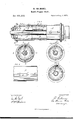
In the accompanying plate of drawings my invention is illustrated; Figure l being a side view in part of a sand-paper roll, and in the remainder a central longitudinal section in the part l 1, along the line x and in the part 2 2, along the line y y, Fig. 2; Figs. 2 and 3, both cross-sections, showing in the one a jaw as closed upon, and in the other as opened from, the roll. Fig. 4 is a side View, illustrating the connecting-band for the several jaws 5 and Fig. 5, a cross-section of Fig. 4.
In the drawings, A represents a roll made of paper or other suitable material. This roll A is hollow along its length,and is closed at each end by a cap-plate, B, applied as shown, or otherwise, in any suitable manner. C, the roll-shaft. This shaft passes throughthe center ofthe roll from end to end, and within the hollow D of the roll the shaft is surrounded by a sleeve, a., which is fastened to it. b, a series of arms which are pivotedV to the shaftsleeve a at intermediate points of its length, and are extended therefrom through suitable apertures c of the roll to outside thereof, where they each terminate in a similar jaw, d, that projects from its arm bin the proper direction, to bear on the periphery of the roll-as, for
instance, as shown in Fig. 2. f, a sharp pin or prong fixed to each jaw d, and g a flat band passing along the several jaws d, and connecting them together.
From the above description, obviously, if the roll-shaft C be turned in one direction, the jaws will be open from the roll-periphery, and if it be turned in the opposite direction the jaws will be closed upon the roll-periphery, and when opened, as stated, the paper sheet can be placed between the jaws and the roll, so that if then the shaft C be properly operated to close the jaws upon the roll, the paper sheet will be firmly and tightly secured to the roll in and between the jaws and the periphery of the roll. The pins f of the jaws, by entering the sand-paper sheet and the roll, (see Figs. 2 and 5,) tend the better to fasten and secure the paper sheet to the roll, and the connecting-band g between the jaws cl acts to lay and to hold and bind the paper sheet to the rollv at its parts between the several jaws along the length of the roll. But both of these features obviously act independently of the operation of the jaws, and it is desirable and preferable to use them, although not absolutely necessary.
After fastening, as described, the sand-paper sheet to the roll, then wind it around the roll, and place theliandshon the roll, one at each end, and by these bands the sand-paper, asv wound on the roll, is secured and held in place. The pivoting of the jaws to the shaft C, as described, gives the jaws, under the operation of the shaft, a more Aor lessswin g in a circular line, and by this swing the jaws are made to draw the paper sheet close about the roll, provided the sand-paper sheet, being of a proper length, is first laid by one edge between the jaws and the roll, and then, after encircling the roll, brought by its other edge between the jaws and the roll, and there held for the pins of the jaws to enter both edges o`f the sheet as the jaws are closed upon the roll.
For encircling the ends of the rolls to hold the sand-paper about and around the rolls, I prefer to use bands h of rubber, as they are easily applied and removed, and,besides being elastic, they compress most perfectly the paper to the roll.
Gompressing-bands h may be used between the ends of the roll as Well as at the ends, as particularly described.
Having thus desoribed lny invention, what neeted to a shaft, C, to swing in circular lines I claim, and desire to secure by Letters Patent, 1s-
1. A hollow roll, A, in combination with jaws d, arranged exteriorly along,` the roll, and adapted to be operated from the inside of the roll, substantially as described, for the purpose specified. Y
2. In combination with a sandpaper roll, the gripingjaws d, having prongs f, and oonwhen operated by said shaft, substantially as described, for the purpose specified.
OTHNIEL GILMORE. Witnesses:
EDWIN W. BROWN, ALBERT W. BROWN,
Publications (1)
| Publication Number | Publication Date |
|---|---|
| US166360A true US166360A (en) | 1875-08-03 |
Family
ID=2235769
Family Applications (1)
| Application Number | Title | Priority Date | Filing Date |
|---|---|---|---|
| US166360D Expired - Lifetime US166360A (en) | Improvement in sand-paper rolls |
Country Status (1)
| Country | Link |
|---|---|
| US (1) | US166360A (en) |
-
0
- US US166360D patent/US166360A/en not_active Expired - Lifetime
Similar Documents
| Publication | Publication Date | Title |
|---|---|---|
| US166360A (en) | Improvement in sand-paper rolls | |
| US1023419A (en) | Winder-shaft collar. | |
| US508822A (en) | Plumber s tack | |
| US288749A (en) | Orvill w | |
| US73609A (en) | David d | |
| US197717A (en) | Improvement in implements for fastening hose-straps | |
| US960013A (en) | Clip or fastener applicable for securing boot-laces and neckties. | |
| US195341A (en) | Improvement in mechanisms for setting eyelet-hooks | |
| US135676A (en) | Improvement in devices for straightening railroad rails | |
| US94090A (en) | Alfred m | |
| US654898A (en) | Lacing-string. | |
| US414115A (en) | Sandpapering-roller | |
| US248093A (en) | Setts | |
| US1019057A (en) | Fastening device or toggle. | |
| US325329A (en) | Buffing-roll | |
| US500806A (en) | Razor-strop | |
| US40545A (en) | Joseph h | |
| US122933A (en) | Improvement in india-rubber bindings for matting | |
| US658402A (en) | Wire-stretcher. | |
| US966787A (en) | Supporting belt or truss. | |
| US269370A (en) | Fowl-fetter | |
| US221951A (en) | Improvement in garment-supporters | |
| US202924A (en) | Improvement in clasps | |
| US795788A (en) | Pivoted clasp. | |
| US856601A (en) | Buffing-roll. |