US1663443A - Punching machine - Google Patents
Punching machine Download PDFInfo
- Publication number
- US1663443A US1663443A US423969A US42396920A US1663443A US 1663443 A US1663443 A US 1663443A US 423969 A US423969 A US 423969A US 42396920 A US42396920 A US 42396920A US 1663443 A US1663443 A US 1663443A
- Authority
- US
- United States
- Prior art keywords
- punches
- punch
- head
- shaft
- machine
- Prior art date
- Legal status (The legal status is an assumption and is not a legal conclusion. Google has not performed a legal analysis and makes no representation as to the accuracy of the status listed.)
- Expired - Lifetime
Links
- 238000004080 punching Methods 0.000 title description 27
- 239000002184 metal Substances 0.000 description 3
- 238000010276 construction Methods 0.000 description 2
- 238000004519 manufacturing process Methods 0.000 description 2
- 102000007469 Actins Human genes 0.000 description 1
- 108010085238 Actins Proteins 0.000 description 1
- 101100340610 Mus musculus Igdcc3 gene Proteins 0.000 description 1
- 101150093941 PORA gene Proteins 0.000 description 1
- 238000009414 blockwork Methods 0.000 description 1
- 239000000463 material Substances 0.000 description 1
- 230000000284 resting effect Effects 0.000 description 1
- 230000000717 retained effect Effects 0.000 description 1
Images
Classifications
-
- B—PERFORMING OPERATIONS; TRANSPORTING
- B21—MECHANICAL METAL-WORKING WITHOUT ESSENTIALLY REMOVING MATERIAL; PUNCHING METAL
- B21D—WORKING OR PROCESSING OF SHEET METAL OR METAL TUBES, RODS OR PROFILES WITHOUT ESSENTIALLY REMOVING MATERIAL; PUNCHING METAL
- B21D28/00—Shaping by press-cutting; Perforating
- B21D28/24—Perforating, i.e. punching holes
- B21D28/32—Perforating, i.e. punching holes in other articles of special shape
-
- Y—GENERAL TAGGING OF NEW TECHNOLOGICAL DEVELOPMENTS; GENERAL TAGGING OF CROSS-SECTIONAL TECHNOLOGIES SPANNING OVER SEVERAL SECTIONS OF THE IPC; TECHNICAL SUBJECTS COVERED BY FORMER USPC CROSS-REFERENCE ART COLLECTIONS [XRACs] AND DIGESTS
- Y10—TECHNICAL SUBJECTS COVERED BY FORMER USPC
- Y10T—TECHNICAL SUBJECTS COVERED BY FORMER US CLASSIFICATION
- Y10T83/00—Cutting
- Y10T83/808—Two tool pairs, driver for one pair moves relative to driver for other pair
- Y10T83/825—Successively acting
-
- Y—GENERAL TAGGING OF NEW TECHNOLOGICAL DEVELOPMENTS; GENERAL TAGGING OF CROSS-SECTIONAL TECHNOLOGIES SPANNING OVER SEVERAL SECTIONS OF THE IPC; TECHNICAL SUBJECTS COVERED BY FORMER USPC CROSS-REFERENCE ART COLLECTIONS [XRACs] AND DIGESTS
- Y10—TECHNICAL SUBJECTS COVERED BY FORMER USPC
- Y10T—TECHNICAL SUBJECTS COVERED BY FORMER US CLASSIFICATION
- Y10T83/00—Cutting
- Y10T83/869—Means to drive or to guide tool
- Y10T83/8821—With simple rectilinear reciprocating motion only
- Y10T83/8841—Tool driver movable relative to tool support
- Y10T83/8843—Cam or eccentric revolving about fixed axis
Definitions
- OneA object of my invention is to provide an improved mechanism for actuating a plurality of punches at one operation, which mechanism is so designed as to require a minimum power output for thepunching operation.
- Another object of my invention is to provide a punching mechanism, which will form a plurality of holes at one operation, the punches operating in dierent phase.
- Another object of my invent-ion is to provide a punching machine comprising a plurality of punches operating along radial lines and other punches actin along lines extending transversely to the p ane containing the radial lines.
- Another object of my invention is to provide a punching machine having right and left hand work supports and cooperating punches ldriven by a common actuating means.
- Another object of my invention is to prof vide a punching machine which is particularly designed to punch, at one operation, radial holes in the flange of a wheel house stamping and, also, holes through. the lateral flange of said stamping.
- Another ob ject of my invention is to provide an improved and more eiiicient punching machine.
- Fig. .II is a sectional view, taken substantially onth'e line II--II of Fig. I: y
- Fig. IV is an end view of the upper part of the machine shown in Fig. I;
- Fig. VI is a detail, sectional view taken on the line VIVI of Fig. V
- Fig. VII is a detail sectional view taken on lthe line VII-VII of Fig. III.
- My invention contemplates a punching machine iii which a plurality of punches are actuated by a common actuating means and move in different phases, so that the punches pass through the metal at different instants, thus reducing the power machine.
- My invention also contemplates the actuation of a series of radial punches, moving in different phases, by a driven shaft. According to one practical embodiment of my invention, such radial punches may be actuated by an eccentric on the shaft and suitable connections to the punches.
- Another feature of my invention resides in the employment of a right hand and lett hand work support, each having a gang or set of punches cooperating therewith, driven from a common source of power but inde-y pendently controlled. ⁇ This is particularly desirable in cases where the punching machine works on stampings ⁇ such as the right and left wheel housings of an automobile body. The character of is determined by the work but, for wheel housings, I prefer to use a work support having a curved upper ledge My invention also concarrying the dies.
- the tonneau may sometimes include wheel housings which may be bolted or riveted to the tonneau panel.
- the curved marginal ⁇ flange has a series of holes formed therein and there are also a pair of holes in another part of the wheel housing extending along lines sub'- stantially perpendicular to the plane containing the axis of the first holes.
- the machine which I have disclosed here, has been designed particularly to punch all of those holes at ,one operation while keeping the maximum power requirement for the machine as low as possible.4 It will be apparent, however, that the inventionembodied in this machine is capable of many other applications and is not to be restricted to this specific arrangement.
- This machine comprises a table, 10, which lnay'be supported by suitable frame work, 11, and which carries a head, 43, which forms the work support and in. which the punch holders may-be slidably mounted.
- the head is provided with a lower, laterally extending ledge, 45 and an upper and narrower laterally extending ledge, 50.
- These ledges are curved to conform to the work, in this instance, the upper and lower flanges of the wheel housing, A.
- I may form a seat, 46, on 'the lowery ledge and mount thereon gauge pins, 47. This forms a very convenient and satisfactory meansfor positioning the lower edge of the wheel housing on the work support.
- I mount the dies, 51, with which the punches cooperate.
- I may form a wor-k supporting surface, 78, against which a flange of the wheel housing lies.
- the punches, 54 which cooperate with the dies, 51, to perforate the upper flange, A1 of the wheel housing, A, are reciprocally mounted with reference to the head, 43. This may be done very satisfactorily by providing guideways, 48, in the head, 43, in which the punch holders, 49, are reciprocally mounted.
- the punch holders, 49 may be retained in the guide ways by the removable cover plates, 52, closing the open sides of the guideways.
- the punches are radiallyarranged and hence the-guideways are formed along lines radiating from a common center.
- the guideways, 48, are formed in one side or face of the head and the ledges forming the work support project from the opposite side or face of the head.
- I provide each punch holder with a head, 53, which overhangs the upper ledge, 50.
- each punch holder may be mounted in each punch holder in l line with the corresponding die, 51.
- Any suitable means for holding the punch, 54, in the head, 53, may be used, for instance, the key, 55. y
- a simple and effective means for actuating the punches consists in connecting the punch holders with a driven shaft so that the rotation of the shaft successively reciprocates the punch holders.
- I provide a drive shaft, 26, which may be journaled, at one end, in a bearing, 27, and, at the other end, in boss, 44, of the head, 43.
- This driven shaft has an eccentric, 63, on which is loosely mounted the collar, 61.
- each punch holder, 49 is connected to this collar.
- One convenient means for accomplishing this is to pivotally connect one end of a link, 56, to the lower end of a punch holder and the other end of the link between flanges, 59 and 60, on the collar, 61.
- These heads are alike with the exception that the ledges, 45 and 50, are so formed as to make a right and a left work support. That is, referring to Fig. 1, the ledges of the work support at the right hand side of the figure are so formedl as to take only a right hand wheel housing and the opposite work support is so formed as to take only ar left hand wheel housing.
- the two heads are identical.
- the gang of punches cooperating with each work su port are driven from a common source o power, but I prefer to provide for their independent control.
- the central drive shaft, 20, is positioned in line with and between the shafts, 26, and may be journaled in suitable bearings, 21 and 22.
- This central drive shaft rotates continuously, so long as the motor, 12, operates, and in order to drive the shafts, 26, independently at the will of the operator, I provide independently controlled clutch connectionsA between-the central drive shaft, 20, and the lindividual drive shafts, 26.
- One very satisfactory clutch comprises a clutch disc, 23, mounted on the end of the shaft, 20, and carrying a pair, of laterally pro]ect ing clutch pins, 24.
- a clutch member ⁇ 25 having a slot, 32, in one edge thereof, in which a latch, 29, is mounted so as to slide parallel to the axis of the shaft.
- a spring, 33 compressed between one end lll() of the latch and a retainer plate, 34, normally presses the latch towards the clutch disc, 23, on the central drive shaft, 20.
- the latch has a projecting portion, 30, which is engaged byl one ofthe clutch pins, 24, so as to drive the clutch member, 25.
- the latch In order to retract the latch out of engagement with the clutch pin, the latch is provided with a radially extending portion having a bevelled nose, 31, to be engaged by the nose of4 a pawl, 35, fulcrumed on bracket, 37.
- a spring, 38 normally 4holds the pawl in position to engage the latch, but the pawl may be Withdrawn against the tension of spring, 38, due to the link, 39, connecting the end of the pawl with the lever, 40, which is fulcrumed at 41, and has the foot pedal, 42.
- the wheel housing, A has a lateral flange, A3, (see Fig. VI) in which two holes are to be formed.
- This flange lies substantially at right angles to the curved flange, A1, in which holes are formed by the radial punches. It was desired in designing this particular machine to form all of these holes at one operation. I have accomplished this by providing a gang of punches for forming the holes in the lateral flan e, A3, and connecting it 'with one of the ra ial punch holders so that 'motion is transmitted from the lat-ter to the former.
- the punch holder has a head, 73, which overhangs the surface, 78, of the Work support.
- the upper end of the slide bar has the jaws, 6'5 and 66, engaging above and below the head, 53, of the adjacent punch holder, 49, so that the slide bar, 67, reciprocates with the punch holder.
- the .lower end of the slide bar, 67 is connected to a link, 68, the opposite end of which is connected to the rear end of the holder, 70.
- the up and down motion of the slide bar, 67 causes a transverse movement of the punchv holder, 70.
- a wheel housing, A is positionedl on the proper work support with flange, A1, resting on the upper ledge, 50, and flange A2, seated on the lower ledge seat, 46.
- the shaft, 26' rotates the punches, 54, successfully enter the metal and coact with the dies, 51, to form the llo-les in flange, A1.
- the punch holder, 70 is reciprocated through its connections with one ofthe radial punch holders, 49, so as to form the holes in the lateral flange, A3.
- the motor, 12, is to run continuously and the clutch connections are controlled and operated through the foot levers to drivelone or the other of the gangs of punches coacting with the right and left work support.
- the clutch is of such a character that it is operable at but one point in each revolution of the shaft and, therefore, the shaft, 26, is always stopped at the same point in its rotation permit-ting the removal of the work from the workisupport.
- the spring brake, 28, aids in this by stopping the shaft as soon as the clutch is thrown out.
- a punching machine comprising a frame, a plurality of punches mounted therein, a drive shaft, an eccentric on said shaft, and independent means controlled by said eccentric for actuating each of said punches in a predetermined sequence.
- a punching machine comprising a frame, a drive shaft, an eccentric on said shaft, a plurality of punches mounted in said frame and reciprocable along lines radial to the axis of and angularly spaced with reference to said shaft, and means controlled by said eccentric for actuating said punches in a predetermined sequence.
- a punching machine comprising a frame,a plurality of punches mounted therein, a drive shaft, an eccentric on said shaft,
- a punching machine comprising a frame, a drive shaft, an eccentric on said shaft, a collarV loosely mounted on said eccentric, a plurality of punches mounted in said frame and reciprocable along lines radial to the axis of said shaft and a plurality of links connecting said collar' and the punches.
- a machine of the class described comprising a head, a plurality of punch holders angularly positioned therein and adapted for rectilinear movement toward and from a. common center, punches carried by said punch holders, a Work support, and means for successively reciprocating a plurality of said punch holders towards the Work support in a predetermined sequence While the Work is in one position on said support.
- a punching ⁇ machine comprising a head, a ledge extending therefrom and forming a Work support, a plurality of punch4 holders reciprocably mounted in said head, each punch holder having a portion overhanging the ledge, punches carried by said overhanging ortions, and means for reciprocating said punch holders.
- a punching machine comprising a head, a vcurved'ledge extending therefrom and forming a Work support, a drive shaft,
- each punch holder mounted in said head and reciprocable along lines radial to the axis of said shaft, each punch holder having a portion overhanging said ledge, punches carried by said overhanging portions, and means actuated by said shaft for reciprocating said punches.
- a punching machine comprising a head, two ledges extending therefrom and forming a Work support, a plurality of punch holders reciprocably mounted in said head, each punch holder having a portion overhanging one of said ledges, punches carried by said punch holders, and means for reciprocating said punch holders.
- a punching machine comprising a head, a substantially horizontal lower ledge and a curved upper ledge formed on said head, a plurality of punch holders reciprocably mounted in said head, punches carried by said punch holders and disposed substantially perpendicular-to said curved upper ledge, and means for reciprocating said punch holders.
- a punching machine comprising a head, having a plurality of radial guideways therein, punch holders reciprocably mounted in said guideways, a Work supporton said head including a curved ledge, punches carried by said punch holders -and extending .substantially perpendicular to said curved ledge, and means for reciprocating said punch holders in predetermined cyclical succession.
- a punching machine comprising a head, a, drive shaft, said head having a plurality of guidevvays formed therein, and extending radially to the axis of said shaft, a Work support on said head including a substantially horizontal lower ledge and a curved upper ledge, a plurality of punch holders reciprocably mounted in said guide- Ways, punches carried by said punch holders and disposed substantially perpendicularly to said curved ledge, and means actuated by said shaft for reciprocating said punch holders.
- a punching machine comprising a head, having a plurality of radial guide- Ways formed therein, a Work support on said head including a curved ledge, a plurality of punch holders reciprocably mounted in said guidcways, punches carried by said punch holders and disposed substantially pcrpendicularly to said curved ledge, and means for actuating said punch holders successively in a predcterinined sequence whereby the punches perfor-ate the Work at successive instants.
- Aimachine for punching holes in nonsymmetrical panels comprising a frame,-a pair of Work supports carried thereby and so formed that one will support right hand panels and the other will support left hand lll panels, a set of punches reciprocable with v respect to each work support, a common actuating means for .said punches, and independent controlling means :for each set of unches.
- a machine of the class described comprising a frame, a drive shaft journaled therein, driven shafts in line therewith, clutch means connecting said driven shafts with said drive shaft, a pair of work supports, said Work supports being non-s mmetrical with respect to a vertical p ane containing the axis of said driven shafts and symmetrical with respect to a vertical plane perpendicular to said axis, a set of punches reciprocable with reference to each Work support and actuated by the respective driven shafts, andindependent means for controlling each of said clutch means.
- a pair of Work supports for non-symmetrical panels respectively arranged to receive and support a right hand and a left hand panel
- a Work support including a ledge and a surface substantially transverse to said ledge, a plurality of punch holders reciprocable normallyto said ledge and said surface respectively, punches carried by said punch holders, .and a common means for actuating said punch holders.
- a punching machine comprising a frame, a punch holder reciprocably mounted therein, means for reciprocating 4said punch holder, a second punch holder mounted to reciprocate in a direction transverse to the first named punch holder, and connections between said punch holders for transmitting movement from one to the other.
- a punchin machine comprising a frame, a punch he der reciprocably mounted therein, means for reci rocating said punch holder, a second punc holder mounted to reciprocate in a direction transverse to the first named punch holder, and a link pivotally connected to said punch holders and transmitting movement from one to the other.
- a punching-machine the combination of a frame, a punch holder slidably mounted therein, and having an overhanging port-ion, a guide block on said overhanging portion, saidframe having a socket in which said block fits, and a punch carriedA by said punch holder.
- Work supports each having a Work supporting ledge, said ledges respectively arranged to receive and support the edge of a right hand and a left hand panel, a set of punches reciprocable With reference to each Work supporting ledge, and means to actuate said punches.
- a punching y machine comprising a support for'the Work to be punched, said support having Work supporting faces substantially perpendicularly disposed relative to each other, and means cooperating with said perpendicularly disposed faces of the Work support for simultaneously punching holes in the Work supported thereon.
Landscapes
- Engineering & Computer Science (AREA)
- Mechanical Engineering (AREA)
- Perforating, Stamping-Out Or Severing By Means Other Than Cutting (AREA)
Description
March 20, 1928.
. 1,663,443 w. H. D'ARDENNE Puucnme cams Filed Nov. 15, 1920- A 4 sneets-sneet3 March 20, 1928.V 1,663,443
w. H. DARDENNE PUNCHING MACHINE AFiled Nov. 13 192C 4 Sheets-Sheet 2 horney March' zo, '1928. Y 1,663,443 W. H. DARDENNE PUNCHING MACHINE Wzzef-Jz miem@ 1 4 i' i mi i l@ if Zio n@ Patented Mar. 20,1928.
UNITED STATES PATENT OFFICE.
WALTER H. DARDENNE, OF PHILADELPHIA, PENNSYLVANIA, ASSIGNOR TO EDWARD G. BUDD MANUFACTURING COMPANY, OF PHILADELPHIA, PENNSYLVANIA, A COR- PORA'IION OF PENNSYLVANIA.
:PUNCHING MACHINE.
Application led November 13, 1920. Serial vNo. 423,969.
to machines for operating a plurality of punches. v I
OneA object of my invention is to provide an improved mechanism for actuating a plurality of punches at one operation, which mechanism is so designed as to require a minimum power output for thepunching operation. i
Another object of my invention is to provide a punching mechanism, which will form a plurality of holes at one operation, the punches operating in dierent phase.
Another object of my invent-ion is to provide a punching machine comprising a plurality of punches operating along radial lines and other punches actin along lines extending transversely to the p ane containing the radial lines.
Another object of my invention is to provide a punching machine having right and left hand work supports and cooperating punches ldriven by a common actuating means. Y
Another object of my invention is to prof vide a punching machine which is particularly designed to punch, at one operation, radial holes in the flange of a wheel house stamping and, also, holes through. the lateral flange of said stamping. Another ob ject of my invention is to provide an improved and more eiiicient punching machine.
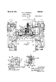
Further objects, and objects relating to economies of manufacture and details 'of construction, will definitely appear from the detailed description to follow. I accomplish the objects of my invention, in one instance,.by the devices and means described in the following specification. My invention is clearly defined and pointed out in the appended claims. A structure constitilting one preferred embodiment of inyinvention is illustrated in the accompanying drawing, forming a part of this specification, in which Fig. I is a top plan view of a machine embodying my invention.
Fig. .II is a sectional view, taken substantially onth'e line II--II of Fig. I: y
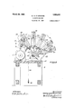
Fig. III is a transverse, sectional view taken substantially =on the line III-III of Fig. I, the gears, clutch members and brakes mounted on the driving shaft, being shown in full lines.
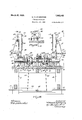
Fig. IV is an end view of the upper part of the machine shown in Fig. I;
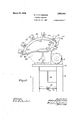
Fig. Vis a fragmentary view showing the means for actuating the horizontally acting punches.
Fig. VI is a detail, sectional view taken on the line VIVI of Fig. V, and Fig. VII is a detail sectional view taken on lthe line VII-VII of Fig. III.
Similar reference numerals refer to similar parts throughout the several views, and the sectional views are `taken looking in the direction of the little arrows at ends of the section lines.
My invention contemplates a punching machine iii which a plurality of punches are actuated by a common actuating means and move in different phases, so that the punches pass through the metal at different instants, thus reducing the power machine. My invention also contemplates the actuation of a series of radial punches, moving in different phases, by a driven shaft. According to one practical embodiment of my invention, such radial punches may be actuated by an eccentric on the shaft and suitable connections to the punches. Another feature of my invention resides in the employment of a right hand and lett hand work support, each having a gang or set of punches cooperating therewith, driven from a common source of power but inde-y pendently controlled.` This is particularly desirable in cases where the punching machine works on stampings `such as the right and left wheel housings of an automobile body. The character of is determined by the work but, for wheel housings, I prefer to usea work support having a curved upper ledge My invention also concarrying the dies.
requirement of the the work supportsto be operated on,
templates the provision of connections with one of thereciprocating punches, acting .0 reciprocate a punch or punches in a direction at an angle to the path of the first punch.
In the construction of automobile'bodies, the tonneau may sometimes include wheel housings which may be bolted or riveted to the tonneau panel. 'In one form of wheel housing, the curved marginal `flange has a series of holes formed therein and there are also a pair of holes in another part of the wheel housing extending along lines sub'- stantially perpendicular to the plane containing the axis of the first holes. The machine, which I have disclosed here, has been designed particularly to punch all of those holes at ,one operation while keeping the maximum power requirement for the machine as low as possible.4 It will be apparent, however, that the inventionembodied in this machine is capable of many other applications and is not to be restricted to this specific arrangement.
This machine comprises a table, 10, which lnay'be supported by suitable frame work, 11, and which carries a head, 43, which forms the work support and in. which the punch holders may-be slidably mounted. In this instance, the head is provided with a lower, laterally extending ledge, 45 and an upper and narrower laterally extending ledge, 50. These ledges are curved to conform to the work, in this instance, the upper and lower flanges of the wheel housing, A. I may form a seat, 46, on 'the lowery ledge and mount thereon gauge pins, 47. This forms a very convenient and satisfactory meansfor positioning the lower edge of the wheel housing on the work support. In the upper ledge, 5,0, I mount the dies, 51, with which the punches cooperate. On the head, 43, adjacent one end of the ledges, 45 and 50, I may form a wor-k supporting surface, 78, against which a flange of the wheel housing lies.
The punches, 54, which cooperate with the dies, 51, to perforate the upper flange, A1 of the wheel housing, A, are reciprocally mounted with reference to the head, 43. This may be done very satisfactorily by providing guideways, 48, in the head, 43, in which the punch holders, 49, are reciprocally mounted. The punch holders, 49, may be retained in the guide ways by the removable cover plates, 52, closing the open sides of the guideways. In the presentinstance,
the punches are radiallyarranged and hence the-guideways are formed along lines radiating from a common center. The guideways, 48, are formed in one side or face of the head and the ledges forming the work support project from the opposite side or face of the head. In order to bring the punches, 54, into line with the dies, 51, I provide each punch holder with a head, 53, which overhangs the upper ledge, 50. A punch, 54,
may be mounted in each punch holder in l line with the corresponding die, 51. Any suitable means for holding the punch, 54, in the head, 53, may be used, for instance, the key, 55. y
In order that the punches may operate in different phase so that they enter the met-al successively, I have found that a simple and effective means for actuating the punches consists in connecting the punch holders with a driven shaft so that the rotation of the shaft successively reciprocates the punch holders. In this particular machine, I provide a drive shaft, 26, which may be journaled, at one end, in a bearing, 27, and, at the other end, in boss, 44, of the head, 43. This driven shaft has an eccentric, 63, on which is loosely mounted the collar, 61.
The lower end of each punch holder, 49, is connected to this collar. One convenient means for accomplishing this is to pivotally connect one end of a link, 56, to the lower end of a punch holder and the other end of the link between flanges, 59 and 60, on the collar, 61.
I have found it very efficient and convenient to provide a head, 43, at each end of the table, 10. These heads are alike with the exception that the ledges, 45 and 50, are so formed as to make a right and a left work support. That is, referring to Fig. 1, the ledges of the work support at the right hand side of the figure are so formedl as to take only a right hand wheel housing and the opposite work support is so formed as to take only ar left hand wheel housing. In other respects the two heads are identical. The gang of punches cooperating with each work su port are driven from a common source o power, but I prefer to provide for their independent control.
In this instance, I accomplish it by providing a separate drive. shaft, 26, for each gang of punches. Each of these drive shafts may have a spring brake, 28, which acts on the shaft to stop its rotation when the power is cut ofi'. The manner in which the indiyvidual drive shafts are driven is not material to my invention, but I have shown a very compact and eficient motor drive. This comprises the motor, 12, mounted on the table, 10, and driving a central shaft, 20, through the train of gearing comprising the gears, 13, 17, 18 -land 19. The gears, 17 and 18, may be carried by an idler shaft, 16, journaled in suitable bearings, 14 and 15. The central drive shaft, 20, is positioned in line with and between the shafts, 26, and may be journaled in suitable bearings, 21 and 22. This central drive shaft rotates continuously, so long as the motor, 12, operates, and in order to drive the shafts, 26, independently at the will of the operator, I provide independently controlled clutch connectionsA between-the central drive shaft, 20, and the lindividual drive shafts, 26. One very satisfactory clutch comprises a clutch disc, 23, mounted on the end of the shaft, 20, and carrying a pair, of laterally pro]ect ing clutch pins, 24. 0n the adjacent' end of the shaft, 26, there is mounted a clutch member` 25, having a slot, 32, in one edge thereof, in which a latch, 29, is mounted so as to slide parallel to the axis of the shaft. A spring, 33, compressed between one end lll() of the latch and a retainer plate, 34, normally presses the latch towards the clutch disc, 23, on the central drive shaft, 20. The latch has a projecting portion, 30, which is engaged byl one ofthe clutch pins, 24, so as to drive the clutch member, 25. In order to retract the latch out of engagement with the clutch pin, the latch is provided with a radially extending portion having a bevelled nose, 31, to be engaged by the nose of4 a pawl, 35, fulcrumed on bracket, 37. A spring, 38, normally 4holds the pawl in position to engage the latch, but the pawl may be Withdrawn against the tension of spring, 38, due to the link, 39, connecting the end of the pawl with the lever, 40, which is fulcrumed at 41, and has the foot pedal, 42.
The wheel housing, A, has a lateral flange, A3, (see Fig. VI) in which two holes are to be formed. This flange lies substantially at right angles to the curved flange, A1, in which holes are formed by the radial punches. It was desired in designing this particular machine to form all of these holes at one operation. I have accomplished this by providing a gang of punches for forming the holes in the lateral flan e, A3, and connecting it 'with one of the ra ial punch holders so that 'motion is transmitted from the lat-ter to the former.
In this instance, I have' accomplished this by mounting in the surface, 78, of the work support, dies, 77, with which the punches, 76, coact. A member, 71, forming part of the frame and fixedon the head, 43, has a punch holder, 70, slidably mounted therein. The punch holder has a head, 73, which overhangs the surface, 78, of the Work support. In order to properly guide the punches and strengthen them against side thrust, I may provide the head, 73, with guide blocks, 74, which fit and work in recesses, 75, of the frame member, 71, and which carry the punches, 76, in line with the dies, 77. I have providedl simple means for reciprocating the punch holder, 70, comprising a slide bar, 67, which is slidably mounted in the guide, 79. The upper end of the slide bar has the jaws, 6'5 and 66, engaging above and below the head, 53, of the adjacent punch holder, 49, so that the slide bar, 67, reciprocates with the punch holder. In order to reciprocate the punch holder, 70, the .lower end of the slide bar, 67, is connected to a link, 68, the opposite end of which is connected to the rear end of the holder, 70. As a result, the up and down motion of the slide bar, 67, causes a transverse movement of the punchv holder, 70. This occurs-because the slide bar, 67, is so guided that it has a straight line movement as it reciprocates with the punch holder, 49. The punch holder, 70, is guided lso that it is confined to a straight line movement. Since the end of the slide bar is connected to the end of punch holder, 70, by the link, 68, a movement of the slide bar, 67, must cause a movement of punch holder, 70, so as to keep the same distance between the ends of such parts.
The operation of this punching machine should be very readily understood from the foregoing description. As the drive shaft, 26, rotates, the connections between the collar, 61, on the eccentric, 63, and the respec tive punch holders, 49, cause the latter to reciprocate successively. That is, these punch holders operate in different phase, no two of them being at the upper limit of their stroke at the same time. As a result, no two of these punches enter the metal at the same time and the power requirementof the machine is kept low because of that fact. This makes a very efficient machine. 'The work,
in this case a wheel housing, A, is positionedl on the proper work support with flange, A1, resting on the upper ledge, 50, and flange A2, seated on the lower ledge seat, 46. As the shaft, 26', rotates the punches, 54, successfully enter the metal and coact with the dies, 51, to form the llo-les in flange, A1. At the same time, the punch holder, 70, is reciprocated through its connections with one ofthe radial punch holders, 49, so as to form the holes in the lateral flange, A3. The motor, 12, is to run continuously and the clutch connections are controlled and operated through the foot levers to drivelone or the other of the gangs of punches coacting with the right and left work support. The clutch is of such a character that it is operable at but one point in each revolution of the shaft and, therefore, the shaft, 26, is always stopped at the same point in its rotation permit-ting the removal of the work from the workisupport. The spring brake, 28, aids in this by stopping the shaft as soon as the clutch is thrown out. y
I am aware that the particular embodiment of my invention, which is disclosed in this application, is susceptible of considerable variation without departing from the spirit of my invention. I desire, therefore,
to claim my invention broadly and also to claim those specific features of the present embodiment which I believe to be of value, all as indicated by the appended claims.
Having thus described my invention, what I claim as new and desire to secure by Letters Patent is 1. A punching machine comprising a frame, a plurality of punches mounted therein, a drive shaft, an eccentric on said shaft, and independent means controlled by said eccentric for actuating each of said punches in a predetermined sequence.
2. A punching machine comprising a frame, a drive shaft, an eccentric on said shaft, a plurality of punches mounted in said frame and reciprocable along lines radial to the axis of and angularly spaced with reference to said shaft, and means controlled by said eccentric for actuating said punches in a predetermined sequence.
i said shaft, and connections between said col lar and said punches.
5. A punching machine comprising a frame,a plurality of punches mounted therein, a drive shaft, an eccentric on said shaft,
a collar loosely mounted on said eccentric, and a plurality of links connecting said collar and said punches. .f
6. A punching machine comprising a frame, a drive shaft, an eccentric on said shaft, a collarV loosely mounted on said eccentric, a plurality of punches mounted in said frame and reciprocable along lines radial to the axis of said shaft and a plurality of links connecting said collar' and the punches.
7. A machine of the class described comprising a head, a plurality of punch holders angularly positioned therein and adapted for rectilinear movement toward and from a. common center, punches carried by said punch holders, a Work support, and means for successively reciprocating a plurality of said punch holders towards the Work support in a predetermined sequence While the Work is in one position on said support.
8. A machine of the-class described comy prising a head, a ledge extending laterally therefrom and forming a Work support, a pluralityy of punches reciprocably mounted in said head and adapted for movement along angularly spaced lines extending peri pendicularly of said work support, and
-means for reciprocating said punches, said means being located substantially at the point of intersection of said angularly spaced lines.
4 9. A punching` machine comprising a head, a ledge extending therefrom and forming a Work support, a plurality of punch4 holders reciprocably mounted in said head, each punch holder having a portion overhanging the ledge, punches carried by said overhanging ortions, and means for reciprocating said punch holders.
10. A punching machine comprising a head, a vcurved'ledge extending therefrom and forming a Work support, a drive shaft,
a plurality of punchholders mounted in said head and reciprocable along lines radial to the axis of said shaft, each punch holder having a portion overhanging said ledge, punches carried by said overhanging portions, and means actuated by said shaft for reciprocating said punches.
11. A punching machine comprising a head, two ledges extending therefrom and forming a Work support, a plurality of punch holders reciprocably mounted in said head, each punch holder having a portion overhanging one of said ledges, punches carried by said punch holders, and means for reciprocating said punch holders.
12. A punching machine comprising a head, a substantially horizontal lower ledge and a curved upper ledge formed on said head, a plurality of punch holders reciprocably mounted in said head, punches carried by said punch holders and disposed substantially perpendicular-to said curved upper ledge, and means for reciprocating said punch holders.
13. A punching machine comprising a head, having a plurality of radial guideways therein, punch holders reciprocably mounted in said guideways, a Work supporton said head including a curved ledge, punches carried by said punch holders -and extending .substantially perpendicular to said curved ledge, and means for reciprocating said punch holders in predetermined cyclical succession.
14. A punching machine comprising a head, a, drive shaft, said head having a plurality of guidevvays formed therein, and extending radially to the axis of said shaft, a Work support on said head including a substantially horizontal lower ledge and a curved upper ledge, a plurality of punch holders reciprocably mounted in said guide- Ways, punches carried by said punch holders and disposed substantially perpendicularly to said curved ledge, and means actuated by said shaft for reciprocating said punch holders.
15. A punching machine comprising a head, having a plurality of radial guide- Ways formed therein, a Work support on said head including a curved ledge, a plurality of punch holders reciprocably mounted in said guidcways, punches carried by said punch holders and disposed substantially pcrpendicularly to said curved ledge, and means for actuating said punch holders successively in a predcterinined sequence whereby the punches perfor-ate the Work at successive instants.
16. Aimachine for punching holes in nonsymmetrical panels comprising a frame,-a pair of Work supports carried thereby and so formed that one will support right hand panels and the other will support left hand lll panels, a set of punches reciprocable with v respect to each work support, a common actuating means for .said punches, and independent controlling means :for each set of unches.
v1 A machine of the class described comprising a frame, a drive shaft journaled therein, driven shafts in line therewith, clutch means connecting said driven shafts with said drive shaft, a pair of work supports, said Work supports being non-s mmetrical with respect to a vertical p ane containing the axis of said driven shafts and symmetrical with respect to a vertical plane perpendicular to said axis, a set of punches reciprocable with reference to each Work support and actuated by the respective driven shafts, andindependent means for controlling each of said clutch means.
18. In a machine ofthe class described, a pair of Work supports for non-symmetrical panels respectively arranged to receive and support a right hand and a left hand panel,
a set of punches reciprocable With reference to each Work support, and means for actuating said punches.
19. In a machine of the class described, the combination of a Work support including a ledge and a surface substantially transverse to said ledge, a plurality of punch holders reciprocable normallyto said ledge and said surface respectively, punches carried by said punch holders, .and a common means for actuating said punch holders.
20. In a machine of the class described, the combination of a reciprocating punch holder, a second punch holder reciprocating substantially transversely thereto, means for reciprocating the first punch holder, and connections between the first and second punch holders, whereby motion is transferred from the first to the second punch holder.
21. A punching machine comprising a frame, a punch holder reciprocably mounted therein, means for reciprocating 4said punch holder, a second punch holder mounted to reciprocate in a direction transverse to the first named punch holder, and connections between said punch holders for transmitting movement from one to the other.
22. A punchin machine comprising a frame, a punch he der reciprocably mounted therein, means for reci rocating said punch holder, a second punc holder mounted to reciprocate in a direction transverse to the first named punch holder, and a link pivotally connected to said punch holders and transmitting movement from one to the other.
23. In a punching-machine, the combination of a frame, a punch holder slidably mounted therein, and having an overhanging port-ion, a guide block on said overhanging portion, saidframe having a socket in which said block fits, and a punch carriedA by said punch holder.
24. In a punching machine, the combination of a frame, a punch holder reciprocably mounted therein, a uide block on said punch holder, said frame aving a socket in which said guide block Works, and `a punch carried by said punch holder.
'25. In a machine of the class described,y
Work supports each having a Work supporting ledge, said ledges respectively arranged to receive and support the edge of a right hand and a left hand panel, a set of punches reciprocable With reference to each Work supporting ledge, and means to actuate said punches.
26. A punching y machine comprising a support for'the Work to be punched, said support having Work supporting faces substantially perpendicularly disposed relative to each other, and means cooperating with said perpendicularly disposed faces of the Work support for simultaneously punching holes in the Work supported thereon.
In testimony whereof,'I aiiix my signature.
' WALTER H. DARDENNE.
Priority Applications (1)
| Application Number | Priority Date | Filing Date | Title |
|---|---|---|---|
| US423969A US1663443A (en) | 1920-11-13 | 1920-11-13 | Punching machine |
Applications Claiming Priority (1)
| Application Number | Priority Date | Filing Date | Title |
|---|---|---|---|
| US423969A US1663443A (en) | 1920-11-13 | 1920-11-13 | Punching machine |
Publications (1)
| Publication Number | Publication Date |
|---|---|
| US1663443A true US1663443A (en) | 1928-03-20 |
Family
ID=23680941
Family Applications (1)
| Application Number | Title | Priority Date | Filing Date |
|---|---|---|---|
| US423969A Expired - Lifetime US1663443A (en) | 1920-11-13 | 1920-11-13 | Punching machine |
Country Status (1)
| Country | Link |
|---|---|
| US (1) | US1663443A (en) |
Cited By (2)
| Publication number | Priority date | Publication date | Assignee | Title |
|---|---|---|---|---|
| US2630467A (en) * | 1946-10-21 | 1953-03-03 | Eaton Mfg Co | Electric clutch and brake controlled press |
| US3485129A (en) * | 1968-01-02 | 1969-12-23 | Frank A Canada | Brakeshoe punching apparatus |
-
1920
- 1920-11-13 US US423969A patent/US1663443A/en not_active Expired - Lifetime
Cited By (2)
| Publication number | Priority date | Publication date | Assignee | Title |
|---|---|---|---|---|
| US2630467A (en) * | 1946-10-21 | 1953-03-03 | Eaton Mfg Co | Electric clutch and brake controlled press |
| US3485129A (en) * | 1968-01-02 | 1969-12-23 | Frank A Canada | Brakeshoe punching apparatus |
Similar Documents
| Publication | Publication Date | Title |
|---|---|---|
| KR20000011868A (en) | Machine for punching and bending metal sheets | |
| US1663443A (en) | Punching machine | |
| US1940883A (en) | Turret punch | |
| US3446499A (en) | Sheet material handling apparatus | |
| JPH0899255A (en) | Sequential feed machining device | |
| US456579A (en) | Punching-machine | |
| US3229556A (en) | Feed control for mechanical presses | |
| US1236508A (en) | Paper-cutting machine. | |
| US1582596A (en) | Punching machine | |
| GB1391497A (en) | Notching machines | |
| US3485131A (en) | Machine for operating on sheet material | |
| US2272751A (en) | Nibbling machine | |
| US3217576A (en) | Plastic article cut-out and perforating apparatus | |
| US842729A (en) | Punching-machine. | |
| US636916A (en) | Stamping-press. | |
| GB1136448A (en) | Machine for upsetting workpieces for the production of screw, bolt and the like blanks | |
| US1389618A (en) | Perforating-machine | |
| US2213566A (en) | Apparatus for perforating metal plates or the like | |
| US1153313A (en) | Machine for folding the corners of pans and the like. | |
| RU2008111630A (en) | EXCENTRIC ROTARY FORMING DEVICE AND METHOD FOR FORMING MOVING SHEET METAL | |
| US3990286A (en) | Piece working machine for the production of punches and/or matrices | |
| US94117A (en) | Improved machine for punching and shearing metal | |
| US1035095A (en) | Punching-machine. | |
| GB327010A (en) | Improvements relating to machines for perforating, cutting or stamping metal or other sheets | |
| US2990742A (en) | Machines for cropping tubes |