US1663294A - Perforating and scoring attachment for printing presses - Google Patents
Perforating and scoring attachment for printing presses Download PDFInfo
- Publication number
- US1663294A US1663294A US17487227A US1663294A US 1663294 A US1663294 A US 1663294A US 17487227 A US17487227 A US 17487227A US 1663294 A US1663294 A US 1663294A
- Authority
- US
- United States
- Prior art keywords
- blade
- attachment
- plunger
- perforating
- plates
- Prior art date
- Legal status (The legal status is an assumption and is not a legal conclusion. Google has not performed a legal analysis and makes no representation as to the accuracy of the status listed.)
- Expired - Lifetime
Links
- 230000033001 locomotion Effects 0.000 description 6
- 238000010276 construction Methods 0.000 description 4
- 230000008933 bodily movement Effects 0.000 description 1
- 229910052729 chemical element Inorganic materials 0.000 description 1
- 230000000994 depressogenic effect Effects 0.000 description 1
- 238000004519 manufacturing process Methods 0.000 description 1
Images
Classifications
-
- B—PERFORMING OPERATIONS; TRANSPORTING
- B41—PRINTING; LINING MACHINES; TYPEWRITERS; STAMPS
- B41G—APPARATUS FOR BRONZE PRINTING, LINE PRINTING, OR FOR BORDERING OR EDGING SHEETS OR LIKE ARTICLES; AUXILIARY FOR PERFORATING IN CONJUNCTION WITH PRINTING
- B41G7/00—Auxiliary perforating apparatus associated with printing devices
- B41G7/006—Auxiliary perforating apparatus associated with printing devices for cylinder presses
-
- Y—GENERAL TAGGING OF NEW TECHNOLOGICAL DEVELOPMENTS; GENERAL TAGGING OF CROSS-SECTIONAL TECHNOLOGIES SPANNING OVER SEVERAL SECTIONS OF THE IPC; TECHNICAL SUBJECTS COVERED BY FORMER USPC CROSS-REFERENCE ART COLLECTIONS [XRACs] AND DIGESTS
- Y10—TECHNICAL SUBJECTS COVERED BY FORMER USPC
- Y10T—TECHNICAL SUBJECTS COVERED BY FORMER US CLASSIFICATION
- Y10T83/00—Cutting
- Y10T83/869—Means to drive or to guide tool
- Y10T83/8737—With tool positioning means synchronized with cutting stroke
- Y10T83/8739—Anvil moves into and out of operative position
Definitions
- the present invention relates to an attachment for printing presses, and more particularly to a mechanism adapted to score or perforate the work or paper along certain lines.
- The-invention pertains more specifically to a' scoring or perforating
- Another object of the invention is to provide a scoring or printing attachment of the type mentioned which is simple in construction, efficient in operation, durable in use and capable of manufacture on a commercial scale, 0r in other words one which is not so diflicult to make as to be beyond the reasonable cost of such a contrivance.
- a further object of the invention is to so design the attachment" that-it may be mounted upon printing presses without necessitating any changes whatever in the construction ofthe latter.
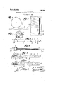
- Figure 1 is aside elevation showing diagrammatically the bed, form and cylinder of a printing press, and also showing the position of the improved scoring or perforating attachment in relation to the elements mentioned;
- Fig. 2 is a top plan view of" the form and scoring or perforating attachment;
- Fig. 3 is a side elevationof the imconstruction within the scope of the ap-,
- Fig. 7 is asection taken on line 77 of Fig. 5; and Fig. 8 is a side elevation, on a larger scale, of a portion of the scoring or perforating blade and its actuating means.
- numeral 10 indicates the bed of a printing press, on which is mounted a form 11, cooperating with a cylinder 12.
- the cylinder supports the material to be printed during the act of impression, the said material being indicated by the numeral 13, it being held in position upon the cylinder by work supporting members 14 of any suitable construction.
- the cylinder is given a rotating motion and the form a reciprocating motion during the act of impression.
- the type 15 and the like is held in a chase 16, in which is also mounted the scoring or perforating attachment 17. i
- the attachment comprises an open housing 18, with which are eithermade integral or to which are attached two. parallel spaced plates 19a Between these plates is inserted a spacing strip 20, held in position by rivets. 21 or otherwise. The height of each plate 19 exceeds considerably that of the spacing strip 20, the said strip being disposed along the lower edges of the said plates. Above the spacing stripis disposed, between the plates 19, a blade 22, extending substantially throughout the length of the plates 19 and being provided with a serrated cutting ed e 23.
- the configuration of the teeth 24 on t e cutting edge may be of any suitable type, ac-
- the blade is provided with slots 25, through which extend pins 26, carried by the plates 19, the arboth directions.
- a recess 31 within which is disposed a bellcranlr lever fulcrumed to the said plunger at 83.
- One end of this bellcrank lever 'engages the plunger 27, while its other end is seated in a notch 34 in an extensionbo of the blade 22, the said extension projecting into the'recess 31 in said plunger.
- a spring coil 36 One end of this coil is fastened to the housing 18, while its other end is attached to the extension of the blade 22. This spring has a tendency to keep the elements in the positions shown in Figs.
- the attachment In use, the attachment is mounted within the chase 16 in a manner that its blade 22 extends in parallel, relation to the axis of the cylinder 1 .of the printing press.
- the upper surface of the plunger 27 projects, however, above the chase, so that, as the form reciprocates in relation to the cylinder 12, the said plunger is depressed by the cylinder, whereby the blade is projected, by the intermediary of the bellcrank lever 32, above the plates 19 into contact with the work, thereby perforating the latter, the ele ments being then in the positions shown in Fig. 6 of the drawings.
- the spring 36 returns the elements to their positions shown in Figs. 3 and-5 of the drawings, whereby the device is ready for the next operation.
- the blade 22 may have a plain cutting edge, for scoring work.
- each of the plates 19 and blade 22 may each be made of a plurality of sec tions, which may be joined together a'ccord ing to the requirements.
- each of the plates may be provided at its outer end with a dove-tailed groove 39, for engagement with the dove-tail of the next plate section.
- the outer end of the blade 22 may be provided with a dovetailed groove 40 for engagement with the dove-tail of the next blade section. Itis'obviousthat the device may be used without change in connection with bed-and platen machines. In the latter case the plunger27 is actuated by the flat platen of the press in the same manner as it is actuated by the cylinder above referred to.
- An attachment for printing presses comprising an open housing, two parallel spaced plates on said housing, a blade movablebetween, said plates, a plunger reciprocably mounted in said housing having one of itsends normally disposed outside of said housing, a connection between said plunger and said blade for causing the cutting edge of said blade "to project beyond its normal position when said plunger is forced into said housing, and a spring for returning said blade and plunger to their normal positions when said plunger is released.
- An attachment for printing presses according to claim 2 comprising spacingmeans between said plates, and inclined c0- acting surfaces on said spacing means and said blade for guiding the movement of the latter between said plates.
- An attachment for printing presses compr sing an open housing, two parallel spaced plates on said housing, a blade movable between said plates, a plunger reciprocable in said housing having one of its ends normally disposed outside of said housing, said plunger being provided with a recess, a bell-crank lever in said recess fulcrumed to said plunger, said blade having an extension projecting into said recess and being provided with a notch, one end of said bellcrank lever abutting against one face of said plunger and the other end of said bellcrank lever being seated in, said notch, whereby upon forcing said plunger into said ion acting surfaces on said spacing means and said blade for guiding the movement of the 10 latter between said plates.
Landscapes
- Handling Of Sheets (AREA)
Description
March 20, 1928. v 1,663,2554
J. A- DAVIDSON PERFORATING AND SCORING ATTACHMENT FOR PRINTING PRESSES Filed March 1 1927 32 35 INVENTOR I 34 9 4 y 3 .32 ATTORNEY Patented Mar. 20, 1928. 1
UNITED STATES PATENT OFFICE. j
JOHN A. DAVIDSON, F GLENDALE, NEW YORK.
Application filed March 12, 1927. Serial no. 174,872.
The present invention relates to an attachment for printing presses, and more particularly to a mechanism adapted to score or perforate the work or paper along certain lines. The-invention pertains more specifically to a' scoring or perforating Another object of the invention is to provide a scoring or printing attachment of the type mentioned which is simple in construction, efficient in operation, durable in use and capable of manufacture on a commercial scale, 0r in other words one which is not so diflicult to make as to be beyond the reasonable cost of such a contrivance.
A further object of the invention is to so design the attachment" that-it may be mounted upon printing presses without necessitating any changes whatever in the construction ofthe latter.
With these and other objects in view, which will more fully appear as thenature of the invention is better understood, the same. consists in the combination, arrangement and construction 'of parts hereinafter described, pointed out in the appended claims and illustrated in the accompanying drawings, it being understood that many changes may be made inthe size and proportion of the several parts and details of pended claims, without departing from the spirit or sacrificing any of the advantages of the invention.
One of the many possible embodiments of the invention is illustrated in the accompanying drawings, in which Figure 1 is aside elevation showing diagrammatically the bed, form and cylinder of a printing press, and also showing the position of the improved scoring or perforating attachment in relation to the elements mentioned; Fig. 2 is a top plan view of" the form and scoring or perforating attachment; Fig. 3 is a side elevationof the imconstruction within the scope of the ap-,
proved attachment, on a larger scale; Fig. i is a top plan view of the device shown in Flg. 3;--Fig. 5 is a section takenon line 55 of Fig. 4; Fig. 6 is a similar section, showing certainelements in other positions; Fig.
7 is asection taken on line 77 of Fig. 5; and Fig. 8 is a side elevation, on a larger scale, of a portion of the scoring or perforating blade and its actuating means. a
. In the drawings, a rolling-contact printingpress has been shown for pur oses of illustration. It will be obvious, however, from the following description of the attachment, that the latter is applicable to other presses just as well. It is applicable more particularly to all presses in which there is a relative bodily movement betweenthe form or printingmember and the opposing ressu re member or platen, irrespective o the fact whether the said pressure member be cylindrical or flat.
-- Referring now to the drawings, the
The attachment comprises an open housing 18, with which are eithermade integral or to which are attached two. parallel spaced plates 19a Between these plates is inserted a spacing strip 20, held in position by rivets. 21 or otherwise. The height of each plate 19 exceeds considerably that of the spacing strip 20, the said strip being disposed along the lower edges of the said plates. Above the spacing stripis disposed, between the plates 19, a blade 22, extending substantially throughout the length of the plates 19 and being provided with a serrated cutting ed e 23. The configuration of the teeth 24 on t e cutting edge may be of any suitable type, ac-
cording to the requirements. The blade is provided with slots 25, through which extend pins 26, carried by the plates 19, the arboth directions. In the plunger is formed a recess 31, within which is disposed a bellcranlr lever fulcrumed to the said plunger at 83. One end of this bellcrank lever'engages the plunger 27, while its other end is seated in a notch 34 in an extensionbo of the blade 22, the said extension projecting into the'recess 31 in said plunger. In the said recessis furthermore arranged a spring coil 36. One end of this coil is fastened to the housing 18, while its other end is attached to the extension of the blade 22. This spring has a tendency to keep the elements in the positions shown in Figs. 3 and 5 of the drawings, in which the plunger 27 is in its elevated and the blade 2:2 in its lowered position. The back of the blade 22 is provided with inclined surfaces 37, co-operating with similar surfaces 38 on the spacing strip 20. When the blade 22 is in its lower position (Fig. 5), it rests upon the spacing strip 20. When the blade is being raised, the inclined surfaces 3? thereof move on the inclined sur faces 38 of the spacing strip 20 until the lower longitudinal edge of the blade rests upon the upper longitudinal edge of the spacing strip. Thereafter the blade is given a longitudinal movement in relation to the spacing strip, so that its lower longitudinal edge will rest upon the spacing strip during the'scoring or perforating operation.
In use, the attachment is mounted within the chase 16 in a manner that its blade 22 extends in parallel, relation to the axis of the cylinder 1 .of the printing press. The
' height of the attachment is such that, with the exception of the plunger 27, it is disposed wholly Within the chase and thus does not interfere with the proper operation of the press. The upper surface of the plunger 27 projects, however, above the chase, so that, as the form reciprocates in relation to the cylinder 12, the said plunger is depressed by the cylinder, whereby the blade is projected, by the intermediary of the bellcrank lever 32, above the plates 19 into contact with the work, thereby perforating the latter, the ele ments being then in the positions shown in Fig. 6 of the drawings. As soon as the cylinder is disengaged from the plunger 27, the spring 36 returns the elements to their positions shown in Figs. 3 and-5 of the drawings, whereby the device is ready for the next operation. The blade 22 may have a plain cutting edge, for scoring work.
In order to adapt the attachment to cylinders of varying sizes, its plates 19 and blade 22 may each be made of a plurality of sec tions, which may be joined together a'ccord ing to the requirements. For this purpose each of the plates may be provided at its outer end with a dove-tailed groove 39, for engagement with the dove-tail of the next plate section. Similarly, the outer end of the blade 22 may be provided with a dovetailed groove 40 for engagement with the dove-tail of the next blade section. Itis'obviousthat the device may be used without change in connection with bed-and platen machines. In the latter case the plunger27 is actuated by the flat platen of the press in the same manner as it is actuated by the cylinder above referred to.
WVhat I claim is:
1.- In a printing press, the combination with a form and a platen having a bodily.
movement in relation to one another, of a blade disposed in said form and adapted to move in and outof-the same, means cooperating with said blade located in the path of and actuated by said platen for causing said blade to project out of said form into engagement with the work carried by said platen, and means for returning said blade to its'normal position on disengagement of said platen from said actuating means.
2." An attachment for printing presses, comprising an open housing, two parallel spaced plates on said housing, a blade movablebetween, said plates, a plunger reciprocably mounted in said housing having one of itsends normally disposed outside of said housing, a connection between said plunger and said blade for causing the cutting edge of said blade "to project beyond its normal position when said plunger is forced into said housing, and a spring for returning said blade and plunger to their normal positions when said plunger is released. q
3. An attachment for printing presses according to claim 2, comprising spacingmeans between said plates, and inclined c0- acting surfaces on said spacing means and said blade for guiding the movement of the latter between said plates.
at. An attachment for printing presses. compr sing an open housing, two parallel spaced plates on said housing, a blade movable between said plates, a plunger reciprocable in said housing having one of its ends normally disposed outside of said housing, said plunger being provided with a recess, a bell-crank lever in said recess fulcrumed to said plunger, said blade having an extension projecting into said recess and being provided with a notch, one end of said bellcrank lever abutting against one face of said plunger and the other end of said bellcrank lever being seated in, said notch, whereby upon forcing said plunger into said ion acting surfaces on said spacing means and said blade for guiding the movement of the 10 latter between said plates.
Signed at New York, in the county of New York, and State of New York, this 28th day of December, A. D. 1926.
JOHN A. DAVIDSON.
Priority Applications (1)
| Application Number | Priority Date | Filing Date | Title |
|---|---|---|---|
| US17487227 US1663294A (en) | 1927-03-12 | 1927-03-12 | Perforating and scoring attachment for printing presses |
Applications Claiming Priority (1)
| Application Number | Priority Date | Filing Date | Title |
|---|---|---|---|
| US17487227 US1663294A (en) | 1927-03-12 | 1927-03-12 | Perforating and scoring attachment for printing presses |
Publications (1)
| Publication Number | Publication Date |
|---|---|
| US1663294A true US1663294A (en) | 1928-03-20 |
Family
ID=22637880
Family Applications (1)
| Application Number | Title | Priority Date | Filing Date |
|---|---|---|---|
| US17487227 Expired - Lifetime US1663294A (en) | 1927-03-12 | 1927-03-12 | Perforating and scoring attachment for printing presses |
Country Status (1)
| Country | Link |
|---|---|
| US (1) | US1663294A (en) |
-
1927
- 1927-03-12 US US17487227 patent/US1663294A/en not_active Expired - Lifetime
Similar Documents
| Publication | Publication Date | Title |
|---|---|---|
| US3176570A (en) | Multiple punch | |
| US1663294A (en) | Perforating and scoring attachment for printing presses | |
| US1497766A (en) | Printing apparatus | |
| US2585612A (en) | Follower for card filing trays | |
| US1856928A (en) | Embossing sheet metal | |
| US2095359A (en) | Automatic punch for printing presses | |
| US3469486A (en) | Paper punching device | |
| US2935941A (en) | Printing plate assembly and its elements | |
| US2415539A (en) | Punch | |
| US1194268A (en) | Walter baxjchwitz | |
| US2060270A (en) | Jogger for a printing press | |
| US2425325A (en) | Printing plate and carrier therefor | |
| US1597534A (en) | Printing-plate holder | |
| US658548A (en) | Punch for platen printing-presses. | |
| US2167746A (en) | Scoring means in printing presses | |
| US2615714A (en) | Sheet receiver for duplicating machines | |
| US2062746A (en) | Auxiliary printing mechanism | |
| US1051206A (en) | Automatic printing-press. | |
| DE575343C (en) | Embossing tool for the cutting edges of thin razor blades | |
| US1910353A (en) | Print guide | |
| US2620729A (en) | Printing apparatus | |
| US1563634A (en) | Paper perforator | |
| US1965724A (en) | Stamping machine | |
| US578219A (en) | Punching attachment for printing-presses | |
| US1085394A (en) | Addressing-machine. |