US1663278A - Rotary swing - Google Patents
Rotary swing Download PDFInfo
- Publication number
- US1663278A US1663278A US182008A US18200827A US1663278A US 1663278 A US1663278 A US 1663278A US 182008 A US182008 A US 182008A US 18200827 A US18200827 A US 18200827A US 1663278 A US1663278 A US 1663278A
- Authority
- US
- United States
- Prior art keywords
- post
- members
- radial
- around
- seats
- Prior art date
- Legal status (The legal status is an assumption and is not a legal conclusion. Google has not performed a legal analysis and makes no representation as to the accuracy of the status listed.)
- Expired - Lifetime
Links
Images

Classifications
-
- A—HUMAN NECESSITIES
- A63—SPORTS; GAMES; AMUSEMENTS
- A63G—MERRY-GO-ROUNDS; SWINGS; ROCKING-HORSES; CHUTES; SWITCHBACKS; SIMILAR DEVICES FOR PUBLIC AMUSEMENT
- A63G1/00—Roundabouts
- A63G1/12—Roundabouts rotated by the passengers themselves
Definitions
- This invention relates to improvements in rotary devices.
- Another object of the invention is to provide a rotary swing wherein the. radial members are held in spaced relation to one another, and wherein other accommodation for additional passengers is so arranged on said members that they are carried, around by the motive power supplied by the working passengers.
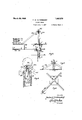
- Figure 1 illustrates a plan view of the invention.
- Figure 2 shows a side view of one radial member and the centre post, partly in section and partly in elevation.”
- Figure 3 is an end view of one of the radial members showing a seat thereon.
- Figure 4 is an enlarged view of the upper end of the central post, showing the method of supporting'the upper ends of the braces for the radial members.
- Figures 5 and 6 are details showing a modified form of support for the stationary centre post.
- Figure 7 shows a modified arrangement of the radial members with circular frames mounted thereon, this view being on a reduced scale.
- 1 designates a centre post supported in a substantially vertical position in any desired manner.
- a sleeve 2 may be sunk in the ground to receive it; the line indicated at 3 in Figure 1 shows the ground level.
- a base having radiating feet 36 may be employed.
- the lower end of the post in that caserests against the out ends of the feet, and a collar 37 is secured around the post as by a pin 38. Attached to the collar are a plurality of rad1atswings intended for useas amusement 1927. Serial No. 182,008.
- braces 39 the outer end of each of which latter is fastened as by a pin 40 to one of the feet.
- a collar 4 Secured around the post 1 is a collar 4; the upper surface of which supports a central plate 5 over which latter a second collar 6, also fixed around the post, may be provided in order to hold the plate in position.
- Radial members 7 and 8 arranged in pairs, are supported onthe plate 5 In this construction it will be seen that the members 7 extend in both directions from the plate and rest thereon substantially centrally of their length, whereas the members 8 project outwardly from the plate and are each lessthan half the length of the members 7.
- the exact numberand arrangement of the radial mem bers is however a matter of choice, and may be varied to suit the style of swing.
- Each pair of radial members are transversely stiffened as by reinforcing members 9, 13 and 15, and secured to the latterin a depending position are bearings 10, 12 and 14.
- a supporting plate 26 is secured, generally welded.
- a crown gear 27 is fixed.
- Meshing with this gear are a plurality of bevel pinions 28, one of which is fastened on the inner end of each of the shafts 11.
- These shafts which are so arranged as to extend substantially radially one under each pair of radial members 7 and 8, are supported by the bearings 10, 12 and 14. Intermediately of their length, and usually between the bearings 10 and 12, these shafts are cranked as shown at 29.
- each pair of radial members 7 and 8 On one of each pair of radial members 7 and 8, and towards their outer ends, supports 31 and 32 are secured to carry a seat 30.
- the device In the construction shown the device is intended to be operated by the riders feet, so the seats should be so positioned as to be substantially centrally located over the cranks 29.
- Otherintermediate seats 33 may also be similarly arranged on the radial members, and in the present instance the shafts are not cranked thereunder; these lat ter seats are intended for smaller children who are so placed that they will not travel as fast as the passengers in the seats 30.
- 34 indicates handles, one of which is arranged opposite each seat and is secured at its lower end to the radial member, 7 or 8, opposite the one to which the supports 31 and 32 are secured. It will be noted that no fastening bers, seat supports, seats, and handles since the connections are, 111 the present instance welded, though when desired other means for fastening the parts to one another may be employed when desired.
- a pocket 16 is inserted which has a flange at its upper end that bears on the upper end of the post.
- the pocket Internally the pocket is circular and terminates at its lower end in 1 substantially semi-spherical concavity.
- the latter supports a ball 17 on which the lower end of the spindle 18 rests.
- This spindle is rotatably supported by the circular wall of the pocket, has an intermediate portion 23 of reduced diameter, and terminates at its upper end in a threaded portion 23.
- the shoulder 19 formed at the junction of the lower and intermediate portions of the spindle is located slightly above the top of the flange 20.
- a rotary element 21 having radial projections integral with it.
- the element is held in position by a nut 22-, shown in the drawings of spherical design, in threaded engagement with the upper end 23* of the spindle.
- 24 designates inclined braces attached at their upper ends to the projections 25 and at their lower ends to the radial members 7 or 8.
- a rotary swing comprising a stationary hollow centre post a frame rotatably mounted around said post, a stationary gear secured around said post, cranked shafts rotatably mounted on said frame, pinions mounted on said shafts and meshing with said stationary gear so that when said cranks are turned said pinions travel around said gear, a pocket in the upper end of said post, having a semi-spherical lower end, a ball in said pocket, a vertical spindle rotatable in said pocket and having-its lower end resting on said ball, a rotary element around the upper end of said spindle above said post,
- braces extending downwardly and outwardly from said element to send frame.
Description
March 20, 1928. 1,663,278
F. w. OLTERSDORF ROTARY SWING Filed April 8, 1927 '2 Sheets-Sheet 1 March 20, 1928. 1,663,278 F. W. OLTERSDORF ROTARY SWING v Filed April 1 927 2 Sheets-Sheet 2 'IIIIIIII/I/A I INVENTOR. fiedc'z zfck W OZZea'sdoy BY Z 2 ATTORNEY.
Patented Mar. 20, 1928.
UNITED STATES,
FREDERICK W. OLTEBSDORE, F DETROIT, MICHIGAN.
* ROTARY SWING.
Application filed April 8,
This invention relates to improvements in rotary devices.
It is an object of the invention to provide a rotary swing having accommodation for passengers which is supported .by radial members rotatably arranged around a stationary centre post; and means so located with respect to the accommodation that some, at least, of the passengers may supply the motive power by which the radial members are driven around their circular path.
Another object of the invention is to provide a rotary swing wherein the. radial members are held in spaced relation to one another, and wherein other accommodation for additional passengers is so arranged on said members that they are carried, around by the motive power supplied by the working passengers.
Having thus broadly outlined the ma or purposes of the invention I Wlll now describe one simple and practical embodiment of the invention with the help of the accompanying drawings, in which;
Figure 1 illustrates a plan view of the invention. c
Figure 2 shows a side view of one radial member and the centre post, partly in section and partly in elevation." v
Figure 3 is an end view of one of the radial members showing a seat thereon.
Figure 4 is an enlarged view of the upper end of the central post, showing the method of supporting'the upper ends of the braces for the radial members.
Figures 5 and 6 are details showing a modified form of support for the stationary centre post.
Figure 7 shows a modified arrangement of the radial members with circular frames mounted thereon, this view being on a reduced scale.
Referring to the drawings, 1 designates a centre post supported in a substantially vertical position in any desired manner. For this purpose, when the installation is to be permanent, a sleeve 2 may be sunk in the ground to receive it; the line indicated at 3 in Figure 1 shows the ground level. For temporary installations a base having radiating feet 36 may be employed. The lower end of the post in that caserests against the out ends of the feet, and a collar 37 is secured around the post as by a pin 38. Attached to the collar are a plurality of rad1atswings intended for useas amusement 1927. Serial No. 182,008.
ing braces 39, the outer end of each of which latter is fastened as by a pin 40 to one of the feet. I
Referring more particularly to Figures 1 L104.- Secured around the post 1 is a collar 4; the upper surface of which supports a central plate 5 over which latter a second collar 6, also fixed around the post, may be provided in order to hold the plate in position.
Radial members 7 and 8, arranged in pairs, are supported onthe plate 5 In this construction it will be seen that the members 7 extend in both directions from the plate and rest thereon substantially centrally of their length, whereas the members 8 project outwardly from the plate and are each lessthan half the length of the members 7. The exact numberand arrangement of the radial mem bers is however a matter of choice, and may be varied to suit the style of swing. Each pair of radial members are transversely stiffened as by reinforcing members 9, 13 and 15, and secured to the latterin a depending position are bearings 10, 12 and 14.
Around the post. 1, and under the collar 1 usually, a supporting plate 26 is secured, generally welded. On this supporting plate a crown gear 27 is fixed. Meshing with this gear are a plurality of bevel pinions 28, one of which is fastened on the inner end of each of the shafts 11. These shafts, which are so arranged as to extend substantially radially one under each pair of radial members 7 and 8, are supported by the bearings 10, 12 and 14. Intermediately of their length, and usually between the bearings 10 and 12, these shafts are cranked as shown at 29.
On one of each pair of radial members 7 and 8, and towards their outer ends, supports 31 and 32 are secured to carry a seat 30. In the construction shown the device is intended to be operated by the riders feet, so the seats should be so positioned as to be substantially centrally located over the cranks 29. Otherintermediate seats 33 may also be similarly arranged on the radial members, and in the present instance the shafts are not cranked thereunder; these lat ter seats are intended for smaller children who are so placed that they will not travel as fast as the passengers in the seats 30. 34 indicates handles, one of which is arranged opposite each seat and is secured at its lower end to the radial member, 7 or 8, opposite the one to which the supports 31 and 32 are secured. It will be noted that no fastening bers, seat supports, seats, and handles since the connections are, 111 the present instance welded, though when desired other means for fastening the parts to one another may be employed when desired.
In the upper end of the post 1, which is tubular, a pocket 16 is inserted which has a flange at its upper end that bears on the upper end of the post. Internally the pocket is circular and terminates at its lower end in 1 substantially semi-spherical concavity. The latter supports a ball 17 on which the lower end of the spindle 18 rests. This spindle is rotatably supported by the circular wall of the pocket, has an intermediate portion 23 of reduced diameter, and terminates at its upper end in a threaded portion 23. The shoulder 19 formed at the junction of the lower and intermediate portions of the spindle is located slightly above the top of the flange 20. Mounted on the intermediate portion and bearing on the said shoulder is a rotary element 21 having radial projections integral with it. The element is held in position by a nut 22-, shown in the drawings of spherical design, in threaded engagement with the upper end 23* of the spindle. 24: designates inclined braces attached at their upper ends to the projections 25 and at their lower ends to the radial members 7 or 8.
In Figure 7 it will be noted that from the central plate 5 a plurality of radial members 7 extend which support inner and outer annular frame members 41. The said frame members support seats and also cross members 42 in the front of the seats. The
said cross members have the lower ends of the handles 34* secured to them. Similar shafts 11 having cranks 22V are arranged undenthe seats. The fragmentary view of this construction is shown in order to convey one of the many variations in construe tion'towhich the invention is susceptible.
Obviously the passengers in the seats 30, or 80, rotate the shafts 11 by turning the cranks 29,'t-hereby causing the pinions 28 to travel around the crown gear 27.
While in the foregoing one embodiment of the invention, and one slightly modified construction, has been described and shown, it is understood that other modifications and alterations may be made therein provided they fall within the scope of the appended claim.
\Vhat I claim as my invention and desire to secure by Letters Patent is:
A rotary swing comprising a stationary hollow centre post a frame rotatably mounted around said post, a stationary gear secured around said post, cranked shafts rotatably mounted on said frame, pinions mounted on said shafts and meshing with said stationary gear so that when said cranks are turned said pinions travel around said gear, a pocket in the upper end of said post, having a semi-spherical lower end, a ball in said pocket, a vertical spindle rotatable in said pocket and having-its lower end resting on said ball, a rotary element around the upper end of said spindle above said post,
and braces extending downwardly and outwardly from said element to send frame.
FREDERICK \V. OLTERSDORF.
Priority Applications (1)
| Application Number | Priority Date | Filing Date | Title |
|---|---|---|---|
| US182008A US1663278A (en) | 1927-04-08 | 1927-04-08 | Rotary swing |
Applications Claiming Priority (1)
| Application Number | Priority Date | Filing Date | Title |
|---|---|---|---|
| US182008A US1663278A (en) | 1927-04-08 | 1927-04-08 | Rotary swing |
Publications (1)
| Publication Number | Publication Date |
|---|---|
| US1663278A true US1663278A (en) | 1928-03-20 |
Family
ID=22666722
Family Applications (1)
| Application Number | Title | Priority Date | Filing Date |
|---|---|---|---|
| US182008A Expired - Lifetime US1663278A (en) | 1927-04-08 | 1927-04-08 | Rotary swing |
Country Status (1)
| Country | Link |
|---|---|
| US (1) | US1663278A (en) |
-
1927
- 1927-04-08 US US182008A patent/US1663278A/en not_active Expired - Lifetime
Similar Documents
| Publication | Publication Date | Title |
|---|---|---|
| US1663278A (en) | Rotary swing | |
| US3073595A (en) | Playground ride | |
| US1368132A (en) | Roundabout | |
| US1426624A (en) | Amusement device | |
| US1654231A (en) | Amusement device | |
| US2368989A (en) | Amusement device | |
| US1720397A (en) | Roundabout | |
| US2242843A (en) | Amusement apparatus | |
| US843908A (en) | Carousel. | |
| USRE17921E (en) | Merry-go-round | |
| US1212109A (en) | Wind-motor. | |
| US770121A (en) | Roundabout. | |
| US799104A (en) | Flower-stand. | |
| US1812946A (en) | Roundabout | |
| US1726262A (en) | Amusement apparatus | |
| US1896796A (en) | Roundabout | |
| US1028418A (en) | Combination clothes-line and merry-go-round. | |
| US1791678A (en) | Whirligig | |
| US1733005A (en) | Merry-go-round | |
| US1070105A (en) | Merry-go-round. | |
| US1518288A (en) | Amusement device | |
| US1494038A (en) | Carrousel | |
| US3203695A (en) | Occupant propelled merry-go-round | |
| US1362864A (en) | Amusement apparatus | |
| US2018655A (en) | Merry go round |