US1663238A - Folding organ - Google Patents
Folding organ Download PDFInfo
- Publication number
- US1663238A US1663238A US753578A US75357824A US1663238A US 1663238 A US1663238 A US 1663238A US 753578 A US753578 A US 753578A US 75357824 A US75357824 A US 75357824A US 1663238 A US1663238 A US 1663238A
- Authority
- US
- United States
- Prior art keywords
- members
- bellows
- organ
- hinged
- frame
- Prior art date
- Legal status (The legal status is an assumption and is not a legal conclusion. Google has not performed a legal analysis and makes no representation as to the accuracy of the status listed.)
- Expired - Lifetime
Links
- 210000000056 organ Anatomy 0.000 title description 19
- 238000010276 construction Methods 0.000 description 2
- 238000005086 pumping Methods 0.000 description 1
Images
Classifications
-
- G—PHYSICS
- G10—MUSICAL INSTRUMENTS; ACOUSTICS
- G10B—ORGANS, HARMONIUMS OR SIMILAR WIND MUSICAL INSTRUMENTS WITH ASSOCIATED BLOWING APPARATUS
- G10B1/00—General design of organs, harmoniums or similar wind musical instruments with associated blowing apparatus
- G10B1/08—General design of organs, harmoniums or similar wind musical instruments with associated blowing apparatus of harmoniums, i.e. reed organs
Definitions
- This invention relates to folding organs and more particularly to the kind in which the stand and mechanism for operating the bellows areadapted to be unfolded from the 6 organ and placed in position for operation,
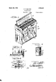
- Figure 1 is a perspective view showing the organ in unfolded position ready for operation.
- Figure 2 is a perspective view showing the organ in folded position ready for being moved about.
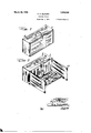
- Figure 3 is a perspective View showing vthe supporting stand in unfolded position before the bellows operating mechanism has 30 been unfolded into position.
- Figure 4 is a cross-section of Figure 2 showing the parts inY folded position.
- Figure 5 is a detail View ofthe catch for securing the engagement between the sides of the stand and a longitudinal member thereof.
- Figure 6 is a detail view showing the catch for holding the bellows into folded posit-ion.
- Numeral 1 represents an organ case, which has a cover 2 adapted to be turned back as shown in Figure 1 to permit operation of the organ and the emission of the sound therefrom.
- a usual organ mechanism is contained in the case- 1 adapted to produce musical notes in the usual manner.
- the bellows is similar to that shown in my prior Patent No. 1,152,475. of September 7th, 1915.
- a frame t of the bellows is secured ⁇ beneath the organ mechanism in the case 1 and is hinged to swing downwardly at the rear edge of said bellows.
- the bellows comprises the pumping members 5 and 6 which are hinged to swing downwardly from the forward end of the 'frame 4 and are provided with springs for normally holding said members upwardly against the frame 4.
- 'A downwardly depending catch 7 as shown in Figure 6 is provided in the casing 1 and is-adapted to be operated from the outf side thereof for catchingthe frame 4t of the bellows and holding it in folded position in said casing.
- Hinged within the bottom of the case 1 beneath the bellows is a longitudinal member 8 which is adapted to open downwardly along the rear edge of said bottom as shown in Figure 3.
- transverse stand members 9 and 10 which are adapted 'to open jd-ownwardly along the sideedges of said bottom and when folded are adapt-ed 'to fold over Vthe longitudinal member 8 inthe case 1.
- the longitudinal member '8 is vadapted when swung downward as shown in said Figure 3 tok tit between the stand members 9 and 10 and hold the latter outwardly.
- Suitable catch members are provided at the lower corners of thel member 8 which are adapted to engage with adjacent lcatch members on the side members 9 and 10 for holding said members from going beyond ⁇ t-he vertical position and for making the stand more rigid.
- Hinged at the lower edge of longitudinal Vmember 8 as shown vin Figure 3 is a frame member 11 which is adapted to swing downwardly along said edge into the position shown in Figure 1.
- flanges 12 Similar tothe catch members referred to on the longitudinal member 8 are provided at the forward outer corners of the frame 11 for engagement with staple members 13 on sides '9 and 10, similar to the aforementioned catch members on said sides for securing said frame 11 to said sides 9 and 10.
- pedals 14 which are connected to the pump members 5 and 6 of the bellows by means of straps 15 and are adapted to actuate said bellows.
- the frame 4.- of the bellows is moved upward from the position shown in Figure 1 to the f position shown in Figure 3 and caught by the catch 7.
- the frame 11 is then folded upwardly from the position shown in said Figure 1 to the position shown in Figure 3.
- the cover 2 is closed and secured.
- the longitudinal member 8 is folded into the casing 1 and the stand members 10 and 9 respec- Cil tively are folded thereover and caught by a catch 16.
- a folding organ comprising ⁇ a ease, a bellows therein, leg members hinged in overlapping relation within said case and ⁇ adapted to be swung .downwardly from the sides thereof, a supporting member also hinged to said case and adapted to be swung downwardly from the rear thereof, said support: ing member being Connected to, and bracing said leg members in the open position, and forming a Cover for said leg members in 'the folded position, a frame member adapted to be unfolded forwardly from said supporting member, and pedal members hinged to said frame member and adapted to actuate said bellows.
- a folding organ comprising a case, a bellows therein, leg members hinged in overlapping relation within said ease and adapted to be swung downwardly from the sides thereof, a supporting ⁇ member also hinged to said ease and adapted to be swung downwardly from Athe rear thereof, said supporting member being connected to, and bracing said leg members in the open position, and forming a Cover for said leg members in the folded position, a frame member adapted vto be unfolded forwardly from .said supporting member, Catch members on said frame member to engage the forward portions of the leg members in the open posi* tion, and pedal members hinged to the front of said frame member and adapted to aetureeaeee ate said bellows, all of said members being adapted to be folded into said ease for transportation.
- a folding organ comprising a ease, a bellows therein, leg panels hinged in overlapping relation within said ease and ladapted to be swung downwardly fronrthe sides thereof, a supporting member also hinged to said oase and adapted to be swung downwardly from the rear thereof for bracing said leg panels, eateh members on said supporting member for engaging the rear portions of said leg panels, a frame member adapted to be unfolded forwardly from said supporting member, eateh members on saidv frame member for engaging the forward portions of said leg panels, and pedal members hinged to the front of said frame member and adapted to actuate said bellows, ⁇ 'the said supporting member forming a' closure for said ease and a cover for said leg panels when the organ is folded foi ⁇ transportation.
- a folding organ comprising a ease,'a bellows therein, flat leg panels hinged in overlapping relation within the opposite ends of the ease, and swingable downwardly and laterally in the open position, va ease bottom closure panel overlying lthe leg panels in the folded position and swingable downwardly and rearwardly, means ⁇ con-- neeting the ⁇ sides of the said closure panel in the open position to the rear edges of the leg panels whereby to brace the latter, a pedal frame hinged to the free edge of the said closure panel Vfor disposition flatwise against the inner face thereofA in the folded position, and swingable downwardly and forwardly therefrom inthe openl position, means connecting the forward Vside portions of said pedal frame to the lower forward edges of the leg panels, and pedals hingedly supported on said frame and having flexible connections with the bellows.
Landscapes
- Physics & Mathematics (AREA)
- Engineering & Computer Science (AREA)
- Acoustics & Sound (AREA)
- Multimedia (AREA)
- Mattresses And Other Support Structures For Chairs And Beds (AREA)
Description
P. P. BILHORN FOLDING ORGAN Mmh 2o, '1928.
2 Sheets-Sheet 1 .m 0 .M m En.. v ,r .m P
March 20, 1928.l
P. P. BILHORN FOLDING `ORGAN Filed Det). 3. 1924 2 Sheets-Sheet 2.
Petey-'P Bihorrl Patented Mar. 20, 192.8.
-UNITED ySTATES PETER P. BILHORN, ory CHICAGO, ILLINOIS.
FOLDING ORGAN.
Application. med December 3, 1924. seriai No. 753,578.
This invention relates to folding organs and more particularly to the kind in which the stand and mechanism for operating the bellows areadapted to be unfolded from the 6 organ and placed in position for operation,
and has for its object the provision of a compact, simple, and easily operated organ which may be quickly unfolded into operating position or folded into position for carrying. It is a further important object of this invention to provide a device o`f this kind which has a maximum of rigidity with a minimum of parts.
lVith the above and other objects in view as will be apparent, this invention consists in the construction, combination and arrangement of parts all as hereinafter more fully described, claimed and illustrated in the accompanying drawing.
On the drawings: y
Figure 1 is a perspective view showing the organ in unfolded position ready for operation. y
Figure 2 is a perspective view showing the organ in folded position ready for being moved about.
Figure 3 is a perspective View showing vthe supporting stand in unfolded position before the bellows operating mechanism has 30 been unfolded into position.
Figure 4 is a cross-section of Figure 2 showing the parts inY folded position.
Figure 5 is a detail View ofthe catch for securing the engagement between the sides of the stand and a longitudinal member thereof. y
Figure 6 is a detail view showing the catch for holding the bellows into folded posit-ion.
As shown on the drawings:
Hinged at the lower edge of longitudinal Vmember 8 as shown vin Figure 3 is a frame member 11 which is adapted to swing downwardly along said edge into the position shown in Figure 1. Depending flanges 12 (Figure 5) similar tothe catch members referred to on the longitudinal member 8 are provided at the forward outer corners of the frame 11 for engagement with staple members 13 on sides '9 and 10, similar to the aforementioned catch members on said sides for securing said frame 11 to said sides 9 and 10. Hinged on the forward edge of frame 11 as shown in Figure 1 are pedals 14 which are connected to the pump members 5 and 6 of the bellows by means of straps 15 and are adapted to actuate said bellows.
In preparing the organ for transportation the frame 4.- of the bellows is moved upward from the position shown in Figure 1 to the f position shown in Figure 3 and caught by the catch 7. The frame 11 is then folded upwardly from the position shown in said Figure 1 to the position shown in Figure 3. The cover 2 is closed and secured. The longitudinal member 8 is folded into the casing 1 and the stand members 10 and 9 respec- Cil tively are folded thereover and caught by a catch 16.
It will be seen that a compact folding organ is provided in which a minimum of parts are used for a maximum amount of ruggedness and rigidity.
It will also be evident that the `organ is simple and sure of operation.
am aware that many changes may be made, and numerous details of construction may be varied through a wide range without departing from the principles Vof this invention, and I therefore do not purpose limiting the patent granted hereon, otherwise than necessitated by the prior art.
I Claim as my invention l. A folding organ, comprising` a ease, a bellows therein, leg members hinged in overlapping relation within said case and`adapted to be swung .downwardly from the sides thereof, a supporting member also hinged to said case and adapted to be swung downwardly from the rear thereof, said support: ing member being Connected to, and bracing said leg members in the open position, and forming a Cover for said leg members in 'the folded position, a frame member adapted to be unfolded forwardly from said supporting member, and pedal members hinged to said frame member and adapted to actuate said bellows.
2. A folding organ, comprising a case, a bellows therein, leg members hinged in overlapping relation within said ease and adapted to be swung downwardly from the sides thereof, a supporting` member also hinged to said ease and adapted to be swung downwardly from Athe rear thereof, said supporting member being connected to, and bracing said leg members in the open position, and forming a Cover for said leg members in the folded position, a frame member adapted vto be unfolded forwardly from .said supporting member, Catch members on said frame member to engage the forward portions of the leg members in the open posi* tion, and pedal members hinged to the front of said frame member and adapted to aetureeaeee ate said bellows, all of said members being adapted to be folded into said ease for transportation.
8. A folding organ, comprising a ease, a bellows therein, leg panels hinged in overlapping relation within said ease and ladapted to be swung downwardly fronrthe sides thereof, a supporting member also hinged to said oase and adapted to be swung downwardly from the rear thereof for bracing said leg panels, eateh members on said supporting member for engaging the rear portions of said leg panels, a frame member adapted to be unfolded forwardly from said supporting member, eateh members on saidv frame member for engaging the forward portions of said leg panels, and pedal members hinged to the front of said frame member and adapted to actuate said bellows,^'the said supporting member forming a' closure for said ease and a cover for said leg panels when the organ is folded foi` transportation.
ln A folding organ comprising a ease,'a bellows therein, flat leg panels hinged in overlapping relation within the opposite ends of the ease, and swingable downwardly and laterally in the open position, va ease bottom closure panel overlying lthe leg panels in the folded position and swingable downwardly and rearwardly, means `con-- neeting the `sides of the said closure panel in the open position to the rear edges of the leg panels whereby to brace the latter, a pedal frame hinged to the free edge of the said closure panel Vfor disposition flatwise against the inner face thereofA in the folded position, and swingable downwardly and forwardly therefrom inthe openl position, means connecting the forward Vside portions of said pedal frame to the lower forward edges of the leg panels, and pedals hingedly supported on said frame and having flexible connections with the bellows.
In testimony whereof l l'iaveihereunto subscribed my name.
PETER BILHORN.
Priority Applications (1)
| Application Number | Priority Date | Filing Date | Title |
|---|---|---|---|
| US753578A US1663238A (en) | 1924-12-03 | 1924-12-03 | Folding organ |
Applications Claiming Priority (1)
| Application Number | Priority Date | Filing Date | Title |
|---|---|---|---|
| US753578A US1663238A (en) | 1924-12-03 | 1924-12-03 | Folding organ |
Publications (1)
| Publication Number | Publication Date |
|---|---|
| US1663238A true US1663238A (en) | 1928-03-20 |
Family
ID=25031253
Family Applications (1)
| Application Number | Title | Priority Date | Filing Date |
|---|---|---|---|
| US753578A Expired - Lifetime US1663238A (en) | 1924-12-03 | 1924-12-03 | Folding organ |
Country Status (1)
| Country | Link |
|---|---|
| US (1) | US1663238A (en) |
Cited By (2)
| Publication number | Priority date | Publication date | Assignee | Title |
|---|---|---|---|---|
| US2487420A (en) * | 1947-02-10 | 1949-11-08 | Charles C Brown | Electroacoustical musical instrument |
| US4380947A (en) * | 1980-06-20 | 1983-04-26 | Nippon Gakki Seizo Kabushiki Kaisha | Portable electronic musical instrument having separable controlling panel and keyboard |
-
1924
- 1924-12-03 US US753578A patent/US1663238A/en not_active Expired - Lifetime
Cited By (2)
| Publication number | Priority date | Publication date | Assignee | Title |
|---|---|---|---|---|
| US2487420A (en) * | 1947-02-10 | 1949-11-08 | Charles C Brown | Electroacoustical musical instrument |
| US4380947A (en) * | 1980-06-20 | 1983-04-26 | Nippon Gakki Seizo Kabushiki Kaisha | Portable electronic musical instrument having separable controlling panel and keyboard |
Similar Documents
| Publication | Publication Date | Title |
|---|---|---|
| US1663238A (en) | Folding organ | |
| US1421929A (en) | Combination table | |
| US431825A (en) | sundback | |
| US3972560A (en) | Chair and table combination | |
| US2107828A (en) | Portable wardrobe, cupboard, or the like | |
| US1568244A (en) | Folding chair | |
| US1167046A (en) | Convertible case or stand. | |
| US1027012A (en) | Foldable chair. | |
| US1724492A (en) | Combination music-sheet holder and stand | |
| US1728430A (en) | Binder | |
| US1646922A (en) | Combined table and camp kit | |
| US2059957A (en) | Obstetric table | |
| US1456670A (en) | Attachment for music sheets | |
| US1426580A (en) | Attachment for davenports | |
| US1341441A (en) | Camping outfit | |
| US1733916A (en) | Combined trunk and bed | |
| US533780A (en) | Portable organ | |
| US1607742A (en) | Automobile bed | |
| US2573104A (en) | Portable nursery chair | |
| US2097604A (en) | Piano case construction | |
| US949340A (en) | Folding display-case. | |
| US1087285A (en) | Folding bed. | |
| US1554310A (en) | Foldable bed structure | |
| US240057A (en) | Fbanz waldeckee | |
| US1256752A (en) | Duofold davenport. |