US1663226A - Nonreversing means for pump heads - Google Patents
Nonreversing means for pump heads Download PDFInfo
- Publication number
- US1663226A US1663226A US108280A US10828026A US1663226A US 1663226 A US1663226 A US 1663226A US 108280 A US108280 A US 108280A US 10828026 A US10828026 A US 10828026A US 1663226 A US1663226 A US 1663226A
- Authority
- US
- United States
- Prior art keywords
- pump
- engager
- rotatable part
- stationary part
- rotatable
- Prior art date
- Legal status (The legal status is an assumption and is not a legal conclusion. Google has not performed a legal analysis and makes no representation as to the accuracy of the status listed.)
- Expired - Lifetime
Links
- XLYOFNOQVPJJNP-UHFFFAOYSA-N water Substances O XLYOFNOQVPJJNP-UHFFFAOYSA-N 0.000 description 5
- 230000002262 irrigation Effects 0.000 description 2
- 238000003973 irrigation Methods 0.000 description 2
- 238000010276 construction Methods 0.000 description 1
Images
Classifications
-
- F—MECHANICAL ENGINEERING; LIGHTING; HEATING; WEAPONS; BLASTING
- F04—POSITIVE - DISPLACEMENT MACHINES FOR LIQUIDS; PUMPS FOR LIQUIDS OR ELASTIC FLUIDS
- F04D—NON-POSITIVE-DISPLACEMENT PUMPS
- F04D15/00—Control, e.g. regulation, of pumps, pumping installations or systems
- F04D15/0077—Safety measures
-
- Y—GENERAL TAGGING OF NEW TECHNOLOGICAL DEVELOPMENTS; GENERAL TAGGING OF CROSS-SECTIONAL TECHNOLOGIES SPANNING OVER SEVERAL SECTIONS OF THE IPC; TECHNICAL SUBJECTS COVERED BY FORMER USPC CROSS-REFERENCE ART COLLECTIONS [XRACs] AND DIGESTS
- Y10—TECHNICAL SUBJECTS COVERED BY FORMER USPC
- Y10S—TECHNICAL SUBJECTS COVERED BY FORMER USPC CROSS-REFERENCE ART COLLECTIONS [XRACs] AND DIGESTS
- Y10S415/00—Rotary kinetic fluid motors or pumps
- Y10S415/901—Drilled well-type pump
Definitions
- This invention relates to pump heads for turbine irrigation pumps.
- a common form of turbine irrigation pump consists of a pump section which is situated 5 near the lower end of a well and from which a column pipe extends upwardly.
- a pump head Connected to the column pipe at the surface of the ground is a pump head.
- This pump head includes a pulley which is driven through a belt by a motor placed a short distance from t-he pump head.
- the pulleyv is connected to a pump shaft which extends downwardly through the column pipe and is attached to impellers in the pump section of the pump. ⁇ When the pulley is properly rotated the impellers are rotated and water is elevated to the surface of the ground through the column pipe. When the pump is shut down the column pipe is filled with with water and this f water will gravitate to the lower end of the well.
- the water acts upon the impellers on the same principle as a reaction turbine and will revolve the pump in a reverse direction. rllhis oftentimes runs the belt off of the pulley and onto the stationary portion of the pump head or may run the motor driving the pump at such an excessive speed that it is greatly damaged. In many cases the belt is damaged.
- .It is 'another object of this invention to provide a non-reversing means for a pump head, which non-reversing means is operated by windage.
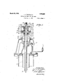
- Fig. 1 is a vertical section through a pump head construction embodying the non-reversing means of my invention.
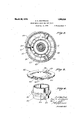
- F ig. 2 is a horizontal section taken on the line 2-2 of Fig. 1.
- Fig. 3 is a view in perspective of a riser plate of the invention
- Fig. l is a view 1n perspective of an engageable member or annular'ratc-het of the' invention. ⁇
- 11 represents al pump head which is ordinarily situated at downwardly vthrough the well and has a.
- a pump section (not shown) attached at the lower end thereof, which pump section carries impellers by means of which water is forced upwardly through the column pipe 12 to the surface of the ground.
- Extending through the column pipe 12 is a pump shaft 15, the lower end 'of this pump shaft being connected to the impellers. of the pump section.
- the upper end of the pump shaft 15 extends through the pump head 11y and the upper end thereof has a nut lscrewed thereonto.
- Surrounding the pump shaft 15 below the nut 16. is ⁇ a thrustv block 17, the upper end or which is engaged by the nut 15.
- the lower end of the thrust block 17 is secured to the upper end of a pulley hub 19 by means of dowel pins 20.
- the pulley hub 19 extends into an ⁇ oil chamber22 of a bearing housing 23.
- the pulley hub is supported by a thrust bearing 241, and the upper part thereof is centralized by radial bearings 25 and 26.
- "Secured to the pulley hub 19l by cap screws 28 is a pulley 29 having a rim 30 which wholly'surrounds; the bearing .housing 23. i
- the bearing housing 23 is provided with an engageable member in the form of an annular ratchet Y 32 having ratchet teeth 33.
- an engageable member in the form of an annular ratchet Y 32 having ratchet teeth 33.
- a riser plate 35 Surrounding the annular ratchet 32 inside the rim 30 of the pulley 29 is a riser plate 35 which is shown in detail in Fig. 3.
- lhisriser plate 35 has radially extending bosses3o' and projecting outwardly from these bosses 36 are guide pins 37.
- the guide pins37 as illustrated best in Figs. 1 and 2, extend into vertically elongated slots'38 formed inthe rim 30 of the pulley 29.
- the riser ring 35 is'sup- 'ported in lower position by engagement of ythe guide pins with the bottom'of the slots 38.
- Projecting inwardly from the radial bosses 36 are engagers in the form of engager pins 11:0.
- These engager pins t() extend inwardly in positions to engage the teeth 33 of the annular ratchet 32 when the riser plate 35 is in the position shown by full lines in Fig, 1 and in Fig-2.
- Securedtothe lower tating direction ot the pulley 3() .being anticlockwise. lVhen the pump head is set into operation, the pulley 30 is revolved in an anti-clockwise diiection as indicated 'by the arrowv 45 in Fig. 2.
- the engager pins 4() at this time ride upwardly on the back 'tacos 46'of the teeth 33 ot the annular ratchet 32.
- the blades situatedon't-lie lower side'oit the riser plate 35 react Vupon the air and the riser plate is forced further upwardly.
- This reaction ot' the blades 43 on the air, due to the rotas tion ofthe riser plate 35, is what is ordinarily termed windage.r
- the riser plate is ytherefore -tirst moved upwardly by the inclined Aback ot the teeth 46 and then moved up into a still higher position,'indicated by dotted lines 448 of Fig. ll, by windage.
- a pump head the combination ot; a stationary part; a rotatable part supported by said stationary part; an engageable ineinber carried by said stationary parti' an engager adapted to engage said engageable member to prevent a reverse rotation oi' said rotatable part; and means operated by wind-age when said rotatable part is rotated .in a proper direction, tor disengaging said engager from said engageable member.
- the combination ot: a stationary part; a rotatable part supported by said stationary part; an engageable niember carried by said stationary part; anwengager adapted to engage said engageable niemeer to prevent a reverse rotation of said rotatable part; and means cairied by said rotatable part and operated by wiiidage when said rotatable part is rotated in a proper direction, tor disengaging said engager from said engageablemember.
- a stationary part a rotatable part supported by said stationary part; an engageable member in ⁇ the form ot a ratchet carried by said stationary part; an engager adapted to engage said engageable member to prevent a reverse rotation ot said rotatable part; and means carried by said rotatable part and operated by windagewhen said rotatable part is rotated in a proper direction, for disengaging said engager from said engageal'ile member.
- a stationary-part a rotatable part supported by said stationary part; an engageablemember in the form of a ratchet carried by'said stationary part; an engager adapted .to engage said engageable 'member to'k prevent a gageable member.
- a stationary part a stationary part
- an annular ratchet carried by said stationary part
- a rotatable part having a pulley surrounding said annular ratchet
- a riser plate carried between saidV pulley and said annular ratchet, said riser plate being adapted toY rotate With said pulley and to be lifted by Windage
- an engager carried by said riser plate adapted to engage said annular ratchet and to prevent a reverse rotation of said rotatable part, said engager being disengaged When said riser plate is lifted.
- a stationary part a rotatable part; an engageable member carried by said stationary part; an engager adapted to engage said engageable member to prevent a reverse rotation of said rotatable part; and means operated by Windage When said rotatable part is rotated in a proper direction, for disengaging said engager from said engageable member'.
- a pump head the combination of: a stationary part; a rotatable part; an engager adapted to prevent a reverse movement of said rotatable part relative to said stationary part; and Windage operated means for mov-r means for preventing a reverse movement of said rotatable part; and wmdage operated means for moving said engaging means into nonoperative position.
- a stationary part a rotatable part
- a riser normally engaging said stationary part and said rotatable part
- means operated by Windage for disengaging said riser and said stationary part when said rotatable part is rotated in a correct direction.
- a pump head the combination stationary part; a rotatable part supported by said stationary part; vand engageable member carried by said stationary part; an engager adapted to engage said engageable member to prevent a reverse rotation of said rotatable part; means operated by Windage y When said rotatable partis rotated in a properfdirection, for disengaging said engager from said engageable member; and means for making said vvindage means operate at a slovv speed of said rotatable part.
- a stationary part a rotatable part; an engager adapted to prevent a reverse movement of said rotatable .part relative to said stationary part; Windage operated means for moving said engager into a non-operative position When said rotatable part is rotated in a proper direction; and means for making said Windage means operate at a slovv speed of said rotatable part.
Landscapes
- Engineering & Computer Science (AREA)
- Mechanical Engineering (AREA)
- General Engineering & Computer Science (AREA)
- Structures Of Non-Positive Displacement Pumps (AREA)
Description
March 20, 1928.
J. A. WINTROATH NONREVERSING MEANS FOR PUMP HEADS Filed May 11. 1926 2 Sheets-Sheet 1 March 2o, 192s. 1,663,226 v J. A. wlNTRoATH NONREVERSINGMEANS FOR PUMP AHEADS Filed May l1. 1926 2 Sheets-5h66?. 2
Patented Mar. 2%, i925.
MENTE@ incazza y paraat? ortica.
JOHN A. wIN'TaoAfrrr, or Los YANefEm'is, oALIronNn, AssIGNon rro rnnannss PUMP COMPANY, on Los ANGELES, CALIFORNIA, A cORroLaATION or CALIFORNIA.
NONREVER-SING MEANS FOR PUMP HEADS.
Application led May 11, 1925. Serial No. 108,280.
This invention relates to pump heads for turbine irrigation pumps.
A common form of turbine irrigation pump consists of a pump section which is situated 5 near the lower end of a well and from which a column pipe extends upwardly. Connected to the column pipe at the surface of the ground is a pump head. This pump head includes a pulley which is driven through a belt by a motor placed a short distance from t-he pump head. The pulleyv is connected to a pump shaft which extends downwardly through the column pipe and is attached to impellers in the pump section of the pump. `When the pulley is properly rotated the impellers are rotated and water is elevated to the surface of the ground through the column pipe. When the pump is shut down the column pipe is filled with with water and this f water will gravitate to the lower end of the well. In so doing, the water acts upon the impellers on the same principle as a reaction turbine and will revolve the pump in a reverse direction. rllhis oftentimes runs the belt off of the pulley and onto the stationary portion of the pump head or may run the motor driving the pump at such an excessive speed that it is greatly damaged. In many cases the belt is damaged.
It is an object of this invention to provide a pump head having means for preventing the pump from being moved in an opposite direction.
.It is 'another object of this invention to provide a non-reversing means for a pump head, which non-reversing means is operated by windage.
Other objects and advantages of this invention will be made evident hereinafter.
Referring to the drawings in whichI illustrate this invention,
Fig. 1 is a vertical section through a pump head construction embodying the non-reversing means of my invention.
F ig. 2 is a horizontal section taken on the line 2-2 of Fig. 1.
Fig. 3 is a view in perspective of a riser plate of the invention Fig. l is a view 1n perspective of an engageable member or annular'ratc-het of the' invention.`
'Referring to the drawings, 11 represents al pump head which is ordinarily situated at downwardly vthrough the well and has a.
pump section (not shown) attached at the lower end thereof, which pump section carries impellers by means of which water is forced upwardly through the column pipe 12 to the surface of the ground. Extending through the column pipe 12 is a pump shaft 15, the lower end 'of this pump shaft being connected to the impellers. of the pump section. The upper end of the pump shaft 15 extends through the pump head 11y and the upper end thereof has a nut lscrewed thereonto. Surrounding the pump shaft 15 below the nut 16.is` a thrustv block 17, the upper end or which is engaged by the nut 15. The lower end of the thrust block 17 is secured to the upper end of a pulley hub 19 by means of dowel pins 20. The pulley hub 19 extends into an `oil chamber22 of a bearing housing 23. The pulley hub is supported by a thrust bearing 241, and the upper part thereof is centralized by radial bearings 25 and 26. "Secured to the pulley hub 19l by cap screws 28 is a pulley 29 having a rim 30 which wholly'surrounds; the bearing .housing 23. i
As shown best in Figs. 2 and 4 the bearing housing 23 is provided with an engageable member in the form of an annular ratchet Y 32 having ratchet teeth 33. Surrounding the annular ratchet 32 inside the rim 30 of the pulley 29 is a riser plate 35 which is shown in detail in Fig. 3. lhisriser plate 35 has radially extending bosses3o' and projecting outwardly from these bosses 36 are guide pins 37. The guide pins37, as illustrated best in Figs. 1 and 2, extend into vertically elongated slots'38 formed inthe rim 30 of the pulley 29. The riser ring 35 is'sup- 'ported in lower position by engagement of ythe guide pins with the bottom'of the slots 38. Projecting inwardly from the radial bosses 36 are engagers in the form of engager pins 11:0. These engager pins t() extend inwardly in positions to engage the teeth 33 of the annular ratchet 32 when the riser plate 35 is in the position shown by full lines in Fig, 1 and in Fig-2. Securedtothe lower tating direction ot the pulley 3() .being anticlockwise. lVhen the pump head is set into operation, the pulley 30 is revolved in an anti-clockwise diiection as indicated 'by the arrowv 45 in Fig. 2. The engager pins 4() at this time ride upwardly on the back 'tacos 46'of the teeth 33 ot the annular ratchet 32. As the pulley 30 gains speed, the blades situatedon't-lie lower side'oit the riser plate 35 react Vupon the air and the riser plate is forced further upwardly. This reaction ot' the blades 43 on the air, due to the rotas tion ofthe riser plate 35, is what is ordinarily termed windage.r The riser plate is ytherefore -tirst moved upwardly by the inclined Aback ot the teeth 46 and then moved up into a still higher position,'indicated by dotted lines 448 of Fig. ll, by windage.
` When the riser plate 35 is in the posit-ion shown'byjdotted lines 48 in Fig. l, the engager pins 40 occupy positions above the teeth 33 of the annular ratchet 32 and there is no engagement between these parts.
vhen the Apump ,head is slowed down and stopped, the windage on the riser plate 35 ceases'and the riser plate will gradually low er into full line position, as shown in the drawings, and the engager vpins 40 will move into engagement with the teeth 33 and again lock the pump head trom rotation in a reversedirection.
I havef'ound that by providing stationary vanes'O, as illustrated in Fig. l, windage suificient to lift the'riser plate 35 becomes effective at a lower' rotational speed ot the y These vanes are formed on. the bearing housing 23 and their yfunction is to prevent alswirlin'g.
of 'the air between the pulley housing 23 and the rim 30 of the pulley 29.
I am aware ot the fact that inventors have heretofore Iprovided non-reversing arrangements 'for pump heads. However, to my knowledge they 'have all employed centrifugal' force for disengaging the parts of their mechanism. My inventionisl different from these prior inventions inasmuch as I do not employ centrifugal torce tor disengaging the engager pins 40 from the annular, ratchet 33, but utilize windage :tor this 'y purpose. IIn t'hetollowing claims I employ the' terms stationary part which refers to that part of' the pump which does not rotate, rotatable'part which refers to thatpart of the pump head which rotates, engageable member which refers to the annular ratchet 32 and engager which refers to the engager pins 40.
I claim as my invent-ion:
l. In a pump head, the combination ot; a stationary part; a rotatable part supported by said stationary part; an engageable ineinber carried by said stationary parti' an engager adapted to engage said engageable member to prevent a reverse rotation oi' said rotatable part; and means operated by wind-age when said rotatable part is rotated .in a proper direction, tor disengaging said engager from said engageable member.
In a puinpliead, the combination ot: a stationary part; a rotatable part supported by said stationary part; an engageable niember carried by said stationary part; anwengager adapted to engage said engageable niemeer to prevent a reverse rotation of said rotatable part; and means cairied by said rotatable part and operated by wiiidage when said rotatable part is rotated in a proper direction, tor disengaging said engager from said engageablemember.
3. In a pump head, 'the combination oit:
stationary part; a rotatable part supported .by .said stationary part; an engageable meinber in the torni oi" a ratchetV carried by said stationary part; an engager adapted to engage said engageable member to prevent a reverse rotation ot said rotatable part; and' means operated by windage when said rotatable part is rotated in a proper direction, for disengaging said engager Lfrom said engageable member. l Y
4. In a pump head, the combination ot :a stationary part; a rotatable part supported by said stationary part; an engageable member in` the form ot a ratchet carried by said stationary part; an engager adapted to engage said engageable member to prevent a reverse rotation ot said rotatable part; and means carried by said rotatable part and operated by windagewhen said rotatable part is rotated in a proper direction, for disengaging said engager from said engageal'ile member.
5. In a pump head, the combination of: a
stationaryipartg a rotatable part supported by said stationary part;` an. engageable member carried by said stationary part; an engager adapted to engage said engageable Vmember to prevent a reverse rotation ot said rotatable part; and a riser plate carried by said rotatable part and operated by windage when saidY rotatable part is rotated in a proper direction, for disenga'ging said engager from said'engageablemember; I
` 6. In a pump head, the combination ot: a stationary-part; a rotatable part supported by said stationary part; an engageablemember in the form of a ratchet carried by'said stationary part; an engager adapted .to engage said engageable 'member to'k prevent a gageable member.
7. In a pump head, the combination of: a stationary part; an annular ratchet carried by said stationary part; a rotatable part having a pulley surrounding said annular ratchet; a riser plate carried between saidV pulley and said annular ratchet, said riser plate being adapted toY rotate With said pulley and to be lifted by Windage; and an engager carried by said riser plate adapted to engage said annular ratchet and to prevent a reverse rotation of said rotatable part, said engager being disengaged When said riser plate is lifted.
8. In a pump head, the combination of: a stationary part; a rotatable part; an engageable member carried by said stationary part; an engager adapted to engage said engageable member to prevent a reverse rotation of said rotatable part; and means operated by Windage When said rotatable part is rotated in a proper direction, for disengaging said engager from said engageable member'.
9. In a pump head, the combination of: a stationary part; a rotatable part; an engager adapted to prevent a reverse movement of said rotatable part relative to said stationary part; and Windage operated means for mov-r means for preventing a reverse movement of said rotatable part; and wmdage operated means for moving said engaging means into nonoperative position. e
11. In a pump head, the combination of: a stationary part; a rotatable part; a riser normally engaging said stationary part and said rotatable part; and means operated by Windage for disengaging said riser and said stationary part when said rotatable part is rotated in a correct direction.
12. In a pump head, the combination stationary part; a rotatable part supported by said stationary part; vand engageable member carried by said stationary part; an engager adapted to engage said engageable member to prevent a reverse rotation of said rotatable part; means operated by Windage y When said rotatable partis rotated in a properfdirection, for disengaging said engager from said engageable member; and means for making said vvindage means operate at a slovv speed of said rotatable part.
13. In a pump head, the combination of: a stationary part; a rotatable part; an engager adapted to prevent a reverse movement of said rotatable .part relative to said stationary part; Windage operated means for moving said engager into a non-operative position When said rotatable part is rotated in a proper direction; and means for making said Windage means operate at a slovv speed of said rotatable part.
In testimony whereof, I have hereunto set my hand at Los Angeles, California, this.
29 day of April, 1926. y
JOHN A. WrNrnoA'rr-r.
Priority Applications (1)
| Application Number | Priority Date | Filing Date | Title |
|---|---|---|---|
| US108280A US1663226A (en) | 1926-05-11 | 1926-05-11 | Nonreversing means for pump heads |
Applications Claiming Priority (1)
| Application Number | Priority Date | Filing Date | Title |
|---|---|---|---|
| US108280A US1663226A (en) | 1926-05-11 | 1926-05-11 | Nonreversing means for pump heads |
Publications (1)
| Publication Number | Publication Date |
|---|---|
| US1663226A true US1663226A (en) | 1928-03-20 |
Family
ID=22321277
Family Applications (1)
| Application Number | Title | Priority Date | Filing Date |
|---|---|---|---|
| US108280A Expired - Lifetime US1663226A (en) | 1926-05-11 | 1926-05-11 | Nonreversing means for pump heads |
Country Status (1)
| Country | Link |
|---|---|
| US (1) | US1663226A (en) |
Cited By (4)
| Publication number | Priority date | Publication date | Assignee | Title |
|---|---|---|---|---|
| US2564838A (en) * | 1945-04-27 | 1951-08-21 | Us Electrical Motors Inc | Motor drive for pump shafts |
| US3799692A (en) * | 1972-09-22 | 1974-03-26 | Carrier Corp | Anti-reverse rotation structure for rotary gas compressors |
| FR2573489A1 (en) * | 1984-11-22 | 1986-05-23 | Rena | Electrical pump for liquids |
| WO2005106253A1 (en) * | 2004-05-05 | 2005-11-10 | Emerson Appliance Motors Europe S.R.L. | An electric synchronous pump with a volute having a tangential outlet |
-
1926
- 1926-05-11 US US108280A patent/US1663226A/en not_active Expired - Lifetime
Cited By (4)
| Publication number | Priority date | Publication date | Assignee | Title |
|---|---|---|---|---|
| US2564838A (en) * | 1945-04-27 | 1951-08-21 | Us Electrical Motors Inc | Motor drive for pump shafts |
| US3799692A (en) * | 1972-09-22 | 1974-03-26 | Carrier Corp | Anti-reverse rotation structure for rotary gas compressors |
| FR2573489A1 (en) * | 1984-11-22 | 1986-05-23 | Rena | Electrical pump for liquids |
| WO2005106253A1 (en) * | 2004-05-05 | 2005-11-10 | Emerson Appliance Motors Europe S.R.L. | An electric synchronous pump with a volute having a tangential outlet |
Similar Documents
| Publication | Publication Date | Title |
|---|---|---|
| US3942026A (en) | Wind turbine with governor | |
| US3265001A (en) | Centrifugal pump | |
| US2775945A (en) | Sand resistant pump | |
| US1170512A (en) | Pump. | |
| US4781531A (en) | Centrifugal pump stage with abrasion resistant elements | |
| US1663226A (en) | Nonreversing means for pump heads | |
| US1949796A (en) | Pump or impeller | |
| US2310816A (en) | Water motor | |
| US2059356A (en) | Windmill | |
| US1387660A (en) | Centrifugal pump | |
| US1634317A (en) | Impeller balancing and sealing device | |
| US1791547A (en) | Centrifugal device for bearings | |
| US1739604A (en) | Fan | |
| US2640427A (en) | Turbine pump | |
| US2614501A (en) | Screw and centrifugal pump | |
| US1286853A (en) | Motor. | |
| US1738210A (en) | Device for increasing buoyancy | |
| US1595636A (en) | Horizontal pump | |
| US2099196A (en) | Electric fan | |
| US1036095A (en) | Pump. | |
| US1314647A (en) | Ernest n | |
| US735692A (en) | High-speed rotary pump. | |
| US1149633A (en) | Deep-well pump. | |
| US2284587A (en) | Regulation of blowers | |
| US1132712A (en) | Hydraulic apparatus. |