US1663190A - Rule - Google Patents
Rule Download PDFInfo
- Publication number
- US1663190A US1663190A US31883A US3188325A US1663190A US 1663190 A US1663190 A US 1663190A US 31883 A US31883 A US 31883A US 3188325 A US3188325 A US 3188325A US 1663190 A US1663190 A US 1663190A
- Authority
- US
- United States
- Prior art keywords
- rule
- section
- sections
- stud
- opening
- Prior art date
- Legal status (The legal status is an assumption and is not a legal conclusion. Google has not performed a legal analysis and makes no representation as to the accuracy of the status listed.)
- Expired - Lifetime
Links
Images
Classifications
-
- G—PHYSICS
- G01—MEASURING; TESTING
- G01B—MEASURING LENGTH, THICKNESS OR SIMILAR LINEAR DIMENSIONS; MEASURING ANGLES; MEASURING AREAS; MEASURING IRREGULARITIES OF SURFACES OR CONTOURS
- G01B3/00—Measuring instruments characterised by the use of mechanical techniques
- G01B3/02—Rulers with scales or marks for direct reading
- G01B3/04—Rulers with scales or marks for direct reading rigid
- G01B3/06—Rulers with scales or marks for direct reading rigid folding
Definitions
- narran stares VVILLIAB F. ⁇ BOAST, OF CASFEB, WYOMING.
- rihis invention relates to .improvements in sectional rules such as are employed by carpenters, and the general object of the invenf tion is'to provide a rule of this type embodying' means whereby it may be employed not only'as a rule but also as a square-and mite'r square, thus enabling vthe user to obtain all necessary 'linear measurements and angular measurements by the use of a single instrument.
- Another obj-ect of the invention is to so construct the rule that the means which is provided ⁇ for holding the several sections thereof in diierent positions of relative an-A gular. adjustment will constitute alsov a means for holding the sections in folded relation to each other.
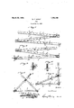
- j 1 Figurel is a plan'view ot the rule embodying the invention, looking at one side thereof.
- 'j Figure 2 is a similar view looking at the other side of the rule.
- Figure 3 is a detail transverse sectiona view taken substantially on the line 3 3 of Figure 1, looking in the direction indi ⁇ cated by the arrows.
- Figure fl is a similar view on the line ll-l of Figure 2, looking in the direction indicated by the arrows.
- Figure-5 is a view similar-to ⁇ Figures 1 and 2, illustrating the sections ot the vrule adjusted to adapt the rule for employment as a Aimiter. square.
- Figure 6 is a similar view illustrating the sect-i ons adjusted to permit of use of the rule as a square.
- FIG. 7 is a detail sectional View takenV substantially on the line 77 of Figure6.
- the rule embodying the invention comprises two end sections, one indicated in ⁇ general by the ⁇ numeral 1, and theother by the numeral Q, and an intermediate section indicated by the numeral 3.
- One end of the section 1 and one end of the section 3 are connected by a pivot joint 11 of a well known type, and one end oi the section 2 and the other end of the section 3 are' similarly cons ncctcd. as indicated by the numeral 5, so that the three sections may be folded to overlie one another when the instrument is not in use, or they may be adjusted to assume various relative angular positions, as will be presently explained, or the sections may be extended to assume a position in alinement with one another, as the user may desire.v
- the section 1 of the rule is provided with two stud members indicated one by the numeral 6 and the otherby the numeral 7 and each of these stud members is of the form shown in Figure 3 of the drawings, this fig*- ure illustrating particularly the stud meme ber 6.
- the sections 1, 2 and 3 are of Vapproximately the same length and the stud member 7 is located approximately midway between the ends of the section 1 and the stud member 6 is located approximately midway between the tree end of thesaid section and the stud member 7, this arrangef ment having been found to :be the one best adapted to ⁇ the attainment of the desired result.
- Openings or sockets 15 and 16 are provided in the section 2 of the'rule, the socket 15 being located near the free eXtremity of the said section and the socket 16 being located a suitable distance inwardly of said ,extremity of the section, and other openings or sockets'l and 18 are provided in the intermediate portion of the section 3,
- the stud members 6 and 7 are lof counterpart construction, and as illustrated in Figure 3 of the drawings, the member, comprises a smallv attaching plate y8 which is riveted or otherwise secured to the base of the sect-ion 1 and may likewise be provided with a rivet projection 9 lfitted through an opening inthe said section of the ruleand headed as shown in ⁇ Figure 3 and likewise in Figurer'?,v vThe stud member proper Sindicated by the numeral 10 and the same projects ⁇ from the outer face of the plate y8 at ⁇ the centerl thereof and .is roundedv at its outer end as at 11 and formed with a notch indicated by thefnumeral 12.
- the rounded end 11 of the stud is of slight-- ly less diameter than the opening or socket into which it is litted and which may be either the opening or socket 1-5 or 16, depending upon the manner in which the sectionsjof the rule are arranged.
- the body of the stud is of slightly greater diameter than the opening or, in other words. of such diameter that it will lit snugly in the opening, and in order that this may be accomplished without binding of the stud so that it can be readily engaged and disengaged.
- the section 2 yot the rule is formed with short longitudinallyextending slits 13 which are radial to the respective Y, about the swivel pin to bring one of its vso ends into engagement iny the 'notch 12 in the stud 10, a finger button 21 'being' preferably provided at the other end of the said stripwhereby it may be convenientlyrotat- Ved about the swivel 20 and thus brought into andout of engagement in the notch in the stud;
- the studV willl bek securely held against withdrawal from the opening 15 or 16, as'the case may f be.
- the rule may bev employed inthe usual' manner A as a rule, vand it will be observed by refer ence to Figures 5 and 6 ofthe drawings, that it may also be employed as a miter square or a right angle square.
- the' sections of the, rule are relatively angularly adjusted tok the position illustrated in the' said4 figure and the stud 6 is engagedr in the socket 16 in the section 2, at which time, the sections 1 and 2 ⁇ will assume a position 'at' an angle of 45 to the section 3.
- the rule for the rule for.
- each section of the rule bear a. linear scale, upon one side, representing twelve inches'divided into inches Vand fractions of inches, so that when the instrument is employed as a square or miter square, any one side ofthe triangle formed by4 the several sections may be employed in makingy measurements as well as determining angles.
- the other sides of the rule sections may be; provided with linear scales 17 and 18 and thus the sections 1 and 3 will be held against relative separation.
- An instrument of the class described comprising end and intermediate sections, the end sections being each pivotally connectedv at one end to a respective end of.I the intermediate section whereby the sections may be relatively angularly adjusted,
- One ofthe end sections having an opening thereinf and being formed with slits extending radially in opposite directions j from the opening whereby to permit of expansion of the opening, andmeans for holding the sec-l tions in a definite position of Vangular adjustment comprising a stud: carried bythe other end section and engageable in the said opening and having an entering end of less diameter than the opening, the body ofthe stud being of a diameter slightly greater than that ofthe opening whereby to'provide for-a tight fitting of the stud in thevopening to prevent disarrangement of the sections when adjusted.
- An instrument of the classdescribed comprising end and intermediate sections, the end-:sections beings each pivotally connected' at one end to a respective end of the intermediate sectionA whereby the sections may be relatively angularly adjusted, one of the end sections having an opening therein, al stud upon lthe other end section engageable in the ⁇ opening and having a notched pro jecting end portion toV project' beyond the opening, the engagement ofthe stud in the openingv serving to hold the several sections inra definite position of angular adjustment, and meansfor restraining the stud' from disengagementV from they opening 'comprisinga' locking member swiveled intermediate its endsy upon the-first mentioned end section at one side ofthe opening therein and engagelable at one end'v in the notchin the stud' and provided at its other end with a linger piece whereby it may be adjustedE into andout of loekingengagement with the stud.
Description
March zo, 192s. 1,663,190
W. F. BOAST RULE Filed May 21, 1925 Patented Mar. Z, 1928,l
narran stares VVILLIAB F.` BOAST, OF CASFEB, WYOMING.
RULE.
Application filed May 21, 1925. Serial No. 31,883.
rihis invention relates to .improvements in sectional rules such as are employed by carpenters, and the general object of the invenf tion is'to provide a rule of this type embodying' means whereby it may be employed not only'as a rule but also as a square-and mite'r square, thus enabling vthe user to obtain all necessary 'linear measurements and angular measurements by the use of a single instrument. v. i
Another obj-ect of the invention is to so construct the rule that the means which is provided `for holding the several sections thereof in diierent positions of relative an-A gular. adjustment will constitute alsov a means for holding the sections in folded relation to each other.
In the accompanying drawings: j 1 Figurel is a plan'view ot the rule embodying the invention, looking at one side thereof. 'j Figure 2 isa similar view looking at the other side of the rule.
Figure 3 is a detail transverse sectiona view taken substantially on the line 3 3 of Figure 1, looking in the direction indi` cated by the arrows. n Figure fl is a similar view on the line ll-l of Figure 2, looking in the direction indicated by the arrows. y .Figure-5 is a view similar-to `Figures 1 and 2, illustrating the sections ot the vrule adjusted to adapt the rule for employment as a Aimiter. square. i
Figure 6 is a similar view illustrating the sect-i ons adjusted to permit of use of the rule as a square.
i Figure 7 is a detail sectional View takenV substantially on the line 77 ofFigure6.,
The rule embodying the invention comprises two end sections, one indicated in `general by the `numeral 1, and theother by the numeral Q, and an intermediate section indicated by the numeral 3. One end of the section 1 and one end of the section 3 are connected bya pivot joint 11 of a well known type, and one end oi the section 2 and the other end of the section 3 are' similarly cons ncctcd. as indicated by the numeral 5, so that the three sections may be folded to overlie one another when the instrument is not in use, or they may be adjusted to assume various relative angular positions, as will be presently explained, or the sections may be extended to assume a position in alinement with one another, as the user may desire.v
v rThe section 1 of the rule is provided with two stud members indicated one by the numeral 6 and the otherby the numeral 7 and each of these stud members is of the form shown in Figure 3 of the drawings, this fig*- ure illustrating particularly the stud meme ber 6. The sections 1, 2 and 3 are of Vapproximately the same length and the stud member 7 is located approximately midway between the ends of the section 1 and the stud member 6 is located approximately midway between the tree end of thesaid section and the stud member 7, this arrangef ment having been found to :be the one best adapted to` the attainment of the desired result. Openings or sockets 15 and 16 are provided in the section 2 of the'rule, the socket 15 being located near the free eXtremity of the said section and the socket 16 being located a suitable distance inwardly of said ,extremity of the section, and other openings or sockets'l and 18 are provided in the intermediate portion of the section 3,
As previously stated, the stud members 6 and 7 are lof counterpart construction, and as illustrated in Figure 3 of the drawings, the member, comprises a smallv attaching plate y8 which is riveted or otherwise secured to the base of the sect-ion 1 and may likewise be provided with a rivet projection 9 lfitted through an opening inthe said section of the ruleand headed as shown in `Figure 3 and likewise in Figurer'?,v vThe stud member proper sindicated by the numeral 10 and the same projects `from the outer face of the plate y8 at` the centerl thereof and .is roundedv at its outer end as at 11 and formed with a notch indicated by thefnumeral 12. The rounded end 11 of the stud is of slight-- ly less diameter than the opening or socket into which it is litted and which may be either the opening or socket 1-5 or 16, depending upon the manner in which the sectionsjof the rule are arranged. The body of the stud, however, is of slightly greater diameter than the opening or, in other words. of such diameter that it will lit snugly in the opening, and in order that this may be accomplished without binding of the stud so that it can be readily engaged and disengaged. the section 2 yot the rule is formed with short longitudinallyextending slits 13 which are radial to the respective Y, about the swivel pin to bring one of its vso ends into engagement iny the 'notch 12 in the stud 10, a finger button 21 'being' preferably provided at the other end of the said stripwhereby it may be convenientlyrotat- Ved about the swivel 20 and thus brought into andout of engagement in the notch in the stud; Of course, when the end of the membery 19 is engaged in the notch, the studV willl bek securely held against withdrawal from the opening 15 or 16, as'the case may f be.
It. will be understood, of course, that the rule may bev employed inthe usual' manner A as a rule, vand it will be observed by refer ence to Figures 5 and 6 ofthe drawings, that it may also be employed as a miter square or a right angle square. In adapting the rule tov be' employed as av milter square, as shown in Figure 5, the' sections of the, rule are relatively angularly adjusted tok the position illustrated in the' said4 figure and the stud 6 is engagedr in the socket 16 in the section 2, at which time, the sections 1 and 2`will assume a position 'at' an angle of 45 to the section 3. In adapting the rule for. use as an ordinary square, the sections are .relatively angularly adjusted; to assume the relationship shown in Figure 6 Vof the drawings, andthestud 7 is engaged in the socket 15 ofthe section 2, so that in this position of the parts the section 1 will extend at right angles to the section 3 'and be held invplace in this position by the section 2.l As illustrated in Figure 2- of the drawings, it is preferable that each section of the rule bear a. linear scale, upon one side, representing twelve inches'divided into inches Vand fractions of inches, so that when the instrument is employed as a square or miter square, any one side ofthe triangle formed by4 the several sections may be employed in makingy measurements as well as determining angles. The other sides of the rule sections may be; provided with linear scales 17 and 18 and thus the sections 1 and 3 will be held against relative separation.
Having thus described the invention, what I claim is:
1'. An instrument of the class described comprising end and intermediate sections, the end sections being each pivotally connectedv at one end to a respective end of.I the intermediate section whereby the sections may be relatively angularly adjusted, One ofthe end sections having an opening thereinf and being formed with slits extending radially in opposite directions j from the opening whereby to permit of expansion of the opening, andmeans for holding the sec-l tions in a definite position of Vangular adjustment comprising a stud: carried bythe other end section and engageable in the said opening and having an entering end of less diameter than the opening, the body ofthe stud being of a diameter slightly greater than that ofthe opening whereby to'provide for-a tight fitting of the stud in thevopening to prevent disarrangement of the sections when adjusted.
2. An instrument of the classdescribed comprising end and intermediate sections, the end-:sections beings each pivotally connected' at one end to a respective end of the intermediate sectionA whereby the sections may be relatively angularly adjusted, one of the end sections having an opening therein, al stud upon lthe other end section engageable in the` opening and having a notched pro jecting end portion toV project' beyond the opening, the engagement ofthe stud in the openingv serving to hold the several sections inra definite position of angular adjustment, and meansfor restraining the stud' from disengagementV from they opening 'comprisinga' locking member swiveled intermediate its endsy upon the-first mentioned end section at one side ofthe opening therein and engagelable at one end'v in the notchin the stud' and provided at its other end with a linger piece whereby it may be adjustedE into andout of loekingengagement with the stud.
In testimony whereof I aiixmy signature.
WILLIAM r. Boas-r: [a 5.31
Priority Applications (1)
| Application Number | Priority Date | Filing Date | Title |
|---|---|---|---|
| US31883A US1663190A (en) | 1925-05-21 | 1925-05-21 | Rule |
Applications Claiming Priority (1)
| Application Number | Priority Date | Filing Date | Title |
|---|---|---|---|
| US31883A US1663190A (en) | 1925-05-21 | 1925-05-21 | Rule |
Publications (1)
| Publication Number | Publication Date |
|---|---|
| US1663190A true US1663190A (en) | 1928-03-20 |
Family
ID=21861902
Family Applications (1)
| Application Number | Title | Priority Date | Filing Date |
|---|---|---|---|
| US31883A Expired - Lifetime US1663190A (en) | 1925-05-21 | 1925-05-21 | Rule |
Country Status (1)
| Country | Link |
|---|---|
| US (1) | US1663190A (en) |
-
1925
- 1925-05-21 US US31883A patent/US1663190A/en not_active Expired - Lifetime
Similar Documents
| Publication | Publication Date | Title |
|---|---|---|
| US1007322A (en) | Tripod. | |
| US1663190A (en) | Rule | |
| US2097361A (en) | Wrench | |
| US2771753A (en) | Segmented band having two pivot joints and a latched joint | |
| US1394088A (en) | Folding rule | |
| US1578157A (en) | Key-holding attachment for belts | |
| US1392825A (en) | Compasses | |
| US1638743A (en) | Pendant ornament | |
| US1872578A (en) | Sketching instrument | |
| US1488875A (en) | Combination instrument | |
| US198065A (en) | Improvement in napkin-ring and holder | |
| US1137169A (en) | Combined square, level, and compass. | |
| US766562A (en) | Combination-rule. | |
| US1477210A (en) | Square | |
| US734539A (en) | Combination-rule. | |
| US1226724A (en) | Locking means for tripods. | |
| US1698420A (en) | Folding table | |
| US818401A (en) | Rule. | |
| US108640A (en) | Improvement in calipers | |
| US1664886A (en) | Jointed rule | |
| USRE5290E (en) | Improvement in dividers | |
| US287168A (en) | manchester | |
| US320995A (en) | Combined darner and mender | |
| US128417A (en) | Improvement in combined rules and dividers | |
| US878801A (en) | Supporting device. |