US1663172A - Casket-retaining device - Google Patents
Casket-retaining device Download PDFInfo
- Publication number
- US1663172A US1663172A US177704A US17770427A US1663172A US 1663172 A US1663172 A US 1663172A US 177704 A US177704 A US 177704A US 17770427 A US17770427 A US 17770427A US 1663172 A US1663172 A US 1663172A
- Authority
- US
- United States
- Prior art keywords
- plate
- casket
- bolt
- clamp
- hearse
- Prior art date
- Legal status (The legal status is an assumption and is not a legal conclusion. Google has not performed a legal analysis and makes no representation as to the accuracy of the status listed.)
- Expired - Lifetime
Links
- 238000004873 anchoring Methods 0.000 description 2
- 238000010276 construction Methods 0.000 description 2
- 238000000465 moulding Methods 0.000 description 2
- 230000000284 resting effect Effects 0.000 description 2
- 208000007256 Nevus Diseases 0.000 description 1
- 238000006073 displacement reaction Methods 0.000 description 1
- 210000005069 ears Anatomy 0.000 description 1
- 238000007689 inspection Methods 0.000 description 1
- 238000009434 installation Methods 0.000 description 1
- 229920000136 polysorbate Polymers 0.000 description 1
Images
Classifications
-
- A—HUMAN NECESSITIES
- A61—MEDICAL OR VETERINARY SCIENCE; HYGIENE
- A61G—TRANSPORT, PERSONAL CONVEYANCES, OR ACCOMMODATION SPECIALLY ADAPTED FOR PATIENTS OR DISABLED PERSONS; OPERATING TABLES OR CHAIRS; CHAIRS FOR DENTISTRY; FUNERAL DEVICES
- A61G21/00—Funeral aspects of hearses or like vehicles
Definitions
- casket holding means of the character indicated preferably associated with casket supports, such as forms the sub-k ject of a patent issued to this applicant 1925, No. 1,565,- 195, wherein rollers are shown which are provided with instrumentalitiesthat are partially imbedded in the bottom of the casket for preventing the casket, although, of course, the inventor does not wish to 'be limited in the use of the invention.
- casket supports such as forms the sub-k ject of a patent issued to this applicant 1925, No. 1,565,- 195, wherein rollers are shown which are provided with instrumentalitiesthat are partially imbedded in the bottom of the casket for preventing the casket, although, of course, the inventor does not wish to 'be limited in the use of the invention.
- lt is a. further object of this invention to produce abutments or lclamping elements for the front and rear ends of a casket, adjustable in positions to operate in conjunction with long or short caskets with equal facility and efficiency.
- lt is a still further objectof this invention to produce adjustable elements or devices which can be expeditiously applied to or removed from coacting parts which are stationed in the hearse.
- the invention consists in thel detailsof construction, and ⁇ in the arrangement and combination of parts to be hereinafter more fully set forth and claimed.
- Figure 2 illustrates a sectional line 2-2 of Fig. 1;
- Figure 3 illustrates a sectional view of part of the device on the line 3-3 of Fig. 2.
- 5 denotes a conventional form of hearse oor having casket view on the lateral shifting movement of vtic'ally disposed flanges supporting rollers 6 with peripheries slightly above the surface of the lloor on which the casket is rolled to position in the hearse.
- the rollers 6 may be of conventional type, although they are preferably madein accordance with the teachings ofthe patent mentioned.
- adjustable means are provided for securing each lend of the casket, although under certain conditions, ture of the inner clamp or abut-ment may be eliminated and the clamp may be stationary and the casket may be m-ovedl into engagement with it., but for the purpose of this disthe adjustable feaclosure, both of the ⁇ clamping elements' are Y,
- the loor ofthe hearse is lon-l gitudinally recessed or grooved, as shown at 7 for the reception of a plate 8 that has ver- 9, whose edges eX- tend outwardly to form' flanges 10 that lie on'the floor of the hearse and are secured thereto by'fastenings 11, such as screws ⁇ or the like.
- the groove in the floor of the hearse is of greater depth thanthe side flanges 9 of the plate 8, and longitudinally extending shoulders 12 are formed ⁇ at thev for a purpose to lbeppresently explained.
- a clamp 17 is preferably provided witha cushioned face 18 a d Vthe clamp is of a con-y iiguration which will partially embrace kthe molding of a casket so that longitudinal movement, as well as vertical movement, of the casket will be prevented when the clamp is properly'set in engagement with the said molding.
- Vthe clamp on the plate between flanges where it is held seated by a nut 20 threaded on the shank 16 of the bolt, it being shown that the shank of the bolt extends through an aperture 21 in the base and the clamp structure, and it is the intention of the ico has a base 19 slidable v the vertically disposed ⁇ inventor that when the nut is manipulated, it
- the head 15 of the bolt may be provided with a lug or spur 22 which will enter a seat or recess 23 formed in. the. under surface of the base of the clamp.V
- the clamp may be slidlongitudinally of the'r plate and its flanges and that thus a guide will be pro vided which willI serve to prevent lateral movement of the cla-mp, It will also be seen that if the clamp is moved to bring the head ofthe bolt into registry with the enlarged area of the slot in the-plate, a clearance will Q be afforded by which the bolt and 4clamp mayberremoved from the plate, ⁇ leaving the floor of the i hearse unobstructed for the movement of the casket when it is placed in or removed' from the hearse.
- the partis just described are'd'uplicated. at the inner end of the floor of the li'earse and the inner clamping member 24 may be adjusted to positions longitudinally of the floor to arrest the inward movement of a casket at any predetermined point, within the length ofthe mounting forthe clamp.
- the nut is knurled externally and the threaded aperture will not extend through the saidl nut,as the arrangement shown will provide a device which is more ornamental than would be the case ⁇ should the nut have anopening in it through which Y the bolt projected;
- a base slidable on*l the plate and guided by the flanges, the saidy base having an aperture therethrough for the reception ofthe shank of the bolt,fan ⁇ d:V an element threaded on the bolt for; drawing the head of the bolt into engagement with the ⁇ under.
Landscapes
- Health & Medical Sciences (AREA)
- Life Sciences & Earth Sciences (AREA)
- Animal Behavior & Ethology (AREA)
- General Health & Medical Sciences (AREA)
- Public Health (AREA)
- Veterinary Medicine (AREA)
- Clamps And Clips (AREA)
Description
March 2o, 192s.
W. B. PARSELS GASKET RETAINING DEVICE Filed March 23, 1927 Patented il ET V ar. 20, 1928.
strata WILLIAM B. PARSELS, OF PLEASANTVILLE, NEVI JERSEY.
oasnnr-anrnrnrno DEVICE.
Application led March 23, 1927. i Serial No. 177,704.
It is furthermore an object of this invenunder date of December 8,
tion to' produce casket holding means of the character indicated preferably associated with casket supports, such as forms the sub-k ject of a patent issued to this applicant 1925, No. 1,565,- 195, wherein rollers are shown which are provided with instrumentalitiesthat are partially imbedded in the bottom of the casket for preventing the casket, although, of course, the inventor does not wish to 'be limited in the use of the invention. Y
lt is a. further object of this invention to produce abutments or lclamping elements for the front and rear ends of a casket, adjustable in positions to operate in conjunction with long or short caskets with equal facility and efficiency.
lt is a still further objectof this invention to produce adjustable elements or devices which can be expeditiously applied to or removed from coacting parts which are stationed in the hearse.
It iS furthermore an object of this inven-l tion to produce clamping devices which will prove strong and durable, of neat appearance and efficient and satisfactory in use.
With the foregoing and -other objects in view, the invention consists in the detailsof construction, and in the arrangement and combination of parts to be hereinafter more fully set forth and claimed.
With the foregoing and other objects in view, the invention consists in thel detailsof construction, and `in the arrangement and combination of parts to be hereinafter more fully set forth and claimed.
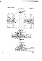
In describing the invention in detail`r reference will be had to the accompanying drawings forming part of this application wherein like characters denote corresponding parts in the several views, and in which- Figure 1 illustrates a plan view of a Hoor of a hearse with devices embodying the in-` vention applied thereto;
Figure 2 illustrates a sectional line 2-2 of Fig. 1; and
Figure 3 illustrates a sectional view of part of the device on the line 3-3 of Fig. 2.
In these drawings, 5 denotes a conventional form of hearse oor having casket view on the lateral shifting movement of vtic'ally disposed flanges supporting rollers 6 with peripheries slightly above the surface of the lloor on which the casket is rolled to position in the hearse. 'As stated heretofore,the rollers 6 may be of conventional type, although they are preferably madein accordance with the teachings ofthe patent mentioned.
Preferably, adjustable means are provided for securing each lend of the casket, although under certain conditions, ture of the inner clamp or abut-ment may be eliminated and the clamp may be stationary and the casket may be m-ovedl into engagement with it., but for the purpose of this disthe adjustable feaclosure, both of the` clamping elements' are Y,
shown as adjustable, and since the parts are duplicated atthe two ends of the floor' of the hearse, except perhaps as to lengths of the guides or the like, a vdetailed description of one of the installations will suilice as a disclosure to one skilled in the art of the means afforded by the invention.
Preferably, the loor ofthe hearse is lon-l gitudinally recessed or grooved, as shown at 7 for the reception of a plate 8 that has ver- 9, whose edges eX- tend outwardly to form' flanges 10 that lie on'the floor of the hearse and are secured thereto by'fastenings 11, such as screws` or the like. The groove in the floor of the hearse is of greater depth thanthe side flanges 9 of the plate 8, and longitudinally extending shoulders 12 are formed` at thev for a purpose to lbeppresently explained.
A clamp 17 is preferably provided witha cushioned face 18 a d Vthe clamp is of a con-y iiguration which will partially embrace kthe molding of a casket so that longitudinal movement, as well as vertical movement, of the casket will be prevented when the clamp is properly'set in engagement with the said molding. rlhe clamp on the plate between flanges where it is held seated by a nut 20 threaded on the shank 16 of the bolt, it being shown that the shank of the bolt extends through an aperture 21 in the base and the clamp structure, and it is the intention of the ico has a base 19 slidable v the vertically disposed` inventor that when the nut is manipulated, it
will act to draw the head of the bolt into engagement with the under surface of the plate 8 with suflicient force to frictionally retain the clamp against accidental displace ment.` As a means for preventing the rotation of the bolt when the nut is being manipulated to tighten the same, the head 15 of the bolt may be provided with a lug or spur 22 which will enter a seat or recess 23 formed in. the. under surface of the base of the clamp.V
It will be seen from an inspection of the draw-ing and from the foregoing description that if the nut is loose, the clamp may be slidlongitudinally of the'r plate and its flanges and that thus a guide will be pro vided which willI serve to prevent lateral movement of the cla-mp, It will also be seen that if the clamp is moved to bring the head ofthe bolt into registry with the enlarged area of the slot in the-plate, a clearance will Q be afforded by which the bolt and 4clamp mayberremoved from the plate, `leaving the floor of the i hearse unobstructed for the movement of the casket when it is placed in or removed' from the hearse.
As stated, the partis just described are'd'uplicated. at the inner end of the floor of the li'earse and the inner clamping member 24 may be adjusted to positions longitudinally of the floor to arrest the inward movement of a casket at any predetermined point, within the length ofthe mounting forthe clamp.
VPreferably thenut is knurled externally and the threaded aperture will not extend through the saidl nut,as the arrangement shown will provide a device which is more ornamental than would be the case` should the nut have anopening in it through which Y the bolt projected;
I clann: t l. In a hearse havinga floor with a-longitudinally extending groove reduced in width at; its bot-to1n,shoulders formed'between the wide and narrow portions of. the groove, a
lateresting on said shoulders, said plate eing slotted longitudinally, upstanding `flanges at nthe edge ofthe plate forming. a
guideymeans foranchoring the plate to the floorv of. the h ears'e,I a bolt having a shank extending through theslot of the plateand at its bottom, shoulders formed between the Wide and narrow portions of the groove, a plate resting on said'shoulders, said plate being slotted longitudinally, flanges at the edge of the plate forminga guide,means'for anchoring the plate to the floor of the hearse, .a bolt having a shank ex tending through the slot of the plate andits' the reduced portion of thev headv slidable in groove under the plate, a casket clamp hav.-` ing a base slidable on the plate and guided by the flanges, the'said baseV having an aperture therethrough for the reception of the shank of the bolt, an element threaded on the bolt for drawing the head of the bolt into engagement with the under surface of the plate, andmeans'forpreventing rotation ofV the said bolt. Y
3. In a hearsehaving al flioorfwith la longitudinally extending groove reduced in width at itsI bottom, shoulders formed be`- tween the wide and narrow portions' of the on said shoulders,saidl groove, a plate resting upstanding`- plate being slottedlongitudinally, upsta'nd ing fiange's'at the'edge'of theplate'formingj a guide, means for anchoring the plate to the floor oftheh'earse,a bolt having a shank extending through the its head slidableinthe reducedportionl of thevgroove under the'plate, a casket-Y clamp having. a base slidable on*l the plate and guided by the flanges, the saidy base having an aperture therethrough for the reception ofthe shank of the bolt,fan`d:V an element threaded on the bolt for; drawing the head of the bolt into engagement with the` under.
surface of the plate, the saidibolth'avinga lug at the preventing rotation of the bolt.A l i WILLIAM B. PARSELS.
slot of theplate and;
l junction of the shank and vhead adapted to fit in a=seat of the clampbasefor.
Priority Applications (1)
| Application Number | Priority Date | Filing Date | Title |
|---|---|---|---|
| US177704A US1663172A (en) | 1927-03-23 | 1927-03-23 | Casket-retaining device |
Applications Claiming Priority (1)
| Application Number | Priority Date | Filing Date | Title |
|---|---|---|---|
| US177704A US1663172A (en) | 1927-03-23 | 1927-03-23 | Casket-retaining device |
Publications (1)
| Publication Number | Publication Date |
|---|---|
| US1663172A true US1663172A (en) | 1928-03-20 |
Family
ID=22649649
Family Applications (1)
| Application Number | Title | Priority Date | Filing Date |
|---|---|---|---|
| US177704A Expired - Lifetime US1663172A (en) | 1927-03-23 | 1927-03-23 | Casket-retaining device |
Country Status (1)
| Country | Link |
|---|---|
| US (1) | US1663172A (en) |
-
1927
- 1927-03-23 US US177704A patent/US1663172A/en not_active Expired - Lifetime
Similar Documents
| Publication | Publication Date | Title |
|---|---|---|
| US2539703A (en) | Single locking wedge | |
| US2625354A (en) | Pipe supporting and anchoring means | |
| US1510978A (en) | Detachable bolt | |
| US1661188A (en) | Wall fixture | |
| US2618145A (en) | Crypt fastener | |
| US1663172A (en) | Casket-retaining device | |
| US1785790A (en) | Combination joist hanger and tie | |
| US2538449A (en) | Bedside clock shelf | |
| US3454979A (en) | Guide unit for sliding doors | |
| US3031669A (en) | Apparatus for aligning, spacing and holding connectors | |
| DE530012C (en) | Pipe fastening | |
| US2307274A (en) | Form clamp | |
| US4003537A (en) | Mountings for tubular metal legs | |
| US1229926A (en) | Railway-rail fastener. | |
| US1461069A (en) | Railroad mine tie and rail fastener | |
| US1454090A (en) | Rail-fastening plate | |
| JPH0316513Y2 (en) | ||
| US1196423A (en) | Combined rail clamp and chair. | |
| US1045757A (en) | Bed-lock. | |
| JPS6244669Y2 (en) | ||
| US1873483A (en) | Crosshead adjuster | |
| JPH0410253Y2 (en) | ||
| US1205183A (en) | Corner-fastening for metal beds and the like. | |
| US1547390A (en) | Tie plate and rail fastening | |
| US1432443A (en) | Railroad tie |