US166313A - Improvement in saw-gummers - Google Patents
Improvement in saw-gummers Download PDFInfo
- Publication number
- US166313A US166313A US166313DA US166313A US 166313 A US166313 A US 166313A US 166313D A US166313D A US 166313DA US 166313 A US166313 A US 166313A
- Authority
- US
- United States
- Prior art keywords
- saw
- arbor
- cutter
- jaws
- ring
- Prior art date
- Legal status (The legal status is an assumption and is not a legal conclusion. Google has not performed a legal analysis and makes no representation as to the accuracy of the status listed.)
- Expired - Lifetime
Links
- 102100038374 Pinin Human genes 0.000 description 1
- 101710173952 Pinin Proteins 0.000 description 1
- 244000221110 common millet Species 0.000 description 1
- 230000007547 defect Effects 0.000 description 1
- 230000001788 irregular Effects 0.000 description 1
Images

Classifications
-
- B—PERFORMING OPERATIONS; TRANSPORTING
- B23—MACHINE TOOLS; METAL-WORKING NOT OTHERWISE PROVIDED FOR
- B23D—PLANING; SLOTTING; SHEARING; BROACHING; SAWING; FILING; SCRAPING; LIKE OPERATIONS FOR WORKING METAL BY REMOVING MATERIAL, NOT OTHERWISE PROVIDED FOR
- B23D63/00—Dressing the tools of sawing machines or sawing devices for use in cutting any kind of material, e.g. in the manufacture of sawing tools
- B23D63/001—Devices for positioning the dressing tool with respect to the saw blade
Definitions
- FIG. B is a carriage-way, provided which my invention relates to make and use with the slides c, and carrying the cross-head the same, reference being had to the accom- B;
- J arbor carrying the cutter G.
- the arpanying drawings, forming part of this specibor is secured in boxes 0, attached to and a fication, in which part of the cross-head B.
- the arbor is pro- Figure l is a perspective view Fig. 2, top. vided with screw-threads, that engage the View; Fig. 3, rear View; Fig. 4, side view of spiral pinion c.
- D threaded feed-screw passjaw; Fig. 5, front view of jaw; Fig.
- FIG. 6 view of ing through a threaded hole in the lug d, and cam-lever; Fig. 7, section showing spiral pinthe bottom journalingin movableboxd. To the ion and thread on arbor; Fig. 8, section of feed-screwDis secured the spiral pinion. c. D, cutter. cam-lever, pivoted at f; and when forced to My invention relates to a saw-gumming the position represented in Fig. 1, the cam, machine; and consists in a ring adjustable in operating upon the movable box d, forces jaws, and provided with a carriage or slides, the spiral pinion 0 to engage the threads on the same carrying a cross-head and cutter-arthe arbor (J.
- the handle contains a position for operation, and in all cases where corresponding thread 01' pin, and when placed the cutter is fed down by hand the feeding is in position to turn the arbor it can move it in irregular consequently the liability of breakbut one direction, and that is in the direction ing the cutter is great, and some of them can for the cutter to out; if it is moved in the oponly be adjusted to suit a particular kind of posite direction it will soon be disengaged saw.
- great annoyance is occutter from being broken.
- the machine can casioned by the unintentional backward movebe operated with one or more handles.
- the threads on the arbor engage the teeth on the pinion c, and cause the same to revolve, which movementrevolves the feed-serew.-
- the arbor containing the cutter, working in boxes secured to the cross-head must necessarily carry the cutter against the saw.
- the cam-lever D comes in contact with the stop D, which movement disengages the cam from the movable box cl, and allows the same to move enough for the pinion c to disengage the thread of the arbor.
- the feed-screw D is then turned backward with'the hand, raising the cross-head to the required height for the next tooth.
- the set-screws b are then loosened, and the machine moved to the next tooth and placed in position, as before.
Landscapes
- Engineering & Computer Science (AREA)
- Mechanical Engineering (AREA)
- Dovetailed Work, And Nailing Machines And Stapling Machines For Wood (AREA)
Description
2 Shank-Sheet 2.
an M. MZ M m J z 7% Z5 m 5 f JLEETRk'PHOTQ-UTHOGRAPHER, WASHINGTON, D c.
UNITED STATES PATENT- OFFICE.
MARVIN 0. SMITH, OF NEW BUFFALO, MICHIGAN, ASSIGNOR TO ISAAC O.
' SMITH, OF SAME PLACE.
IMPROVE'MENT IN 'SAW-GUMMERS.
Specification forming part of Letters Patent No. 166,3] 3, dated August 3, 1875; application filed February 3, 1875.
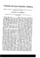
To all whom it may concern: face of the ring. A portion of the flanges are Be it known that I, MARVIN O. SMITH, of removed at 11, this being necessary, as the New Buffalo, in the county of Berrien and jaws are placed on the ring at this point, and State of Michigan, have invented a new and the flange a enters the dovetail grooves a, useful Improvement in Saw-Gumming Maand the jaws are then moved to any point de chines; and I hereby declare the following to sired on the ring, and secured in position by be a full, clear, and exact description thereof, forcing the setscrews 1) against the periphery which will enable others skilled in the art to of the ring. B is a carriage-way, provided which my invention relates to make and use with the slides c, and carrying the cross-head the same, reference being had to the accom- B; (J, arbor carrying the cutter G. The arpanying drawings, forming part of this specibor is secured in boxes 0, attached to and a fication, in which part of the cross-head B. The arbor is pro- Figure l is a perspective view Fig. 2, top. vided with screw-threads, that engage the View; Fig. 3, rear View; Fig. 4, side view of spiral pinion c. D, threaded feed-screw passjaw; Fig. 5, front view of jaw; Fig. 6, view of ing through a threaded hole in the lug d, and cam-lever; Fig. 7, section showing spiral pinthe bottom journalingin movableboxd. To the ion and thread on arbor; Fig. 8, section of feed-screwDis secured the spiral pinion. c. D, cutter. cam-lever, pivoted at f; and when forced to My invention relates to a saw-gumming the position represented in Fig. 1, the cam, machine; and consists in a ring adjustable in operating upon the movable box d, forces jaws, and provided with a carriage or slides, the spiral pinion 0 to engage the threads on the same carrying a cross-head and cutter-arthe arbor (J. When the tooth of the saw is cut her, and with self feeding mechanism at to the desired depth the outer end of the lever tached; and my invention further consists ina D comes in contact with the stop D, which screw-thread on the end or ends of the cutterforces the cam-lever to a perpendicular posiarbor to receive the handle. tion, and allows a spring behind the box to There are several saw-gumming machines force the same out enough to allow the pinin use at the present time; but all of them ion 0 to disengage the threads on the arbor. have some objectionable points. In some it cl, screw-thread on the end of the arbor to retakes too much time to place them in the right ceive the handle. The handle contains a position for operation, and in all cases where corresponding thread 01' pin, and when placed the cutter is fed down by hand the feeding is in position to turn the arbor it can move it in irregular consequently the liability of breakbut one direction, and that is in the direction ing the cutter is great, and some of them can for the cutter to out; if it is moved in the oponly be adjusted to suit a particular kind of posite direction it will soon be disengaged saw. In all saw-gumming machines where a from the arbor, and by so doing will save the rotary cutter is used great annoyance is occutter from being broken. The machine can casioned by the unintentional backward movebe operated with one or more handles. ment of thehandle, which, even in the slightest The operation of my machine is as follows: degree, will remove a portion of the edge of the When a saw is to be gummed the machine is cutter that comes in contact with the saw, all placed upon the same so thatthe saw occuof which defects are overcome by myimprovepics the slots c in the jaws A. The set-screws ment in saw-gumming machines, and which b are forced down upon the saw, so as to hold will be more fully explained hereinafter. the machine firmly to the same. The ring A In the accompanying drawing, A represents is then adjusted in the jaws to the desired angle the jaws, each provided on one side with the of the tooth to be out. When this is accomdovetail groove a, and the lower portion of the pli'shed the set-screws b are forced down and jaw provided with the slot at; A, ring prosecure the ring firmly in position. The camvided with the flange 0/ upon its periphery, lever D is then placed in the position repreand a corresponding flange on the inner sursented in Fig. l, which movement forces the teeth on the spiral pinion c to engage the screw-th read on the arbor O. The handle is then turned in the desired direction. The threads on the arbor engage the teeth on the pinion c, and cause the same to revolve, which movementrevolves the feed-serew.- The threads on the same, engaging the corresponding threads in the lug (1, cause the same to force the cross-head in the direction required. The arbor containing the cutter, working in boxes secured to the cross-head, must necessarily carry the cutter against the saw. When the required depth is reached the cam-lever D comes in contact with the stop D, which movement disengages the cam from the movable box cl, and allows the same to move enough for the pinion c to disengage the thread of the arbor. The feed-screw D is then turned backward with'the hand, raising the cross-head to the required height for the next tooth. The set-screws b are then loosened, and the machine moved to the next tooth and placed in position, as before.
Having thus described my invention, what I claim as new, and desire to secure by Letters Patent, is-
1. In a saw-gunnning machine, the combination of the ring A, provided with the flanges a, jaws A, having dovetail grooves a and slots a, carriage-way B, provided with slides a, and cross-head B, arbor G, cutter 0, boxes a",
spiral pinion c, feed-screw D, cam-lever D,
movable box d, lug d, and stop D, when the several parts are arranged to operate substantially as described, and for the purpose set forth.
2. In a saw-gumming machine, the combination of the rim A, provided with the flanges a, with the jaws A, having the dovetailed grooves 00 and slots at, said rim A being adapted for adjustment within the jaws A, to suit the different angles necessary in gumming saws, substantially as described and shown.
3. In a saw-guniming machine, the combination of the arbor O and cutter C with the spiral pinion c, secured near the base. of the feed-screw D, substantially as and for the purpose described.
The above specification signed by me this 28th day of January, 1875.
MARVIN 0. SMITH.
Witnesses:
J. M. SMITH, A. D. HODGE.
Publications (1)
| Publication Number | Publication Date |
|---|---|
| US166313A true US166313A (en) | 1875-08-03 |
Family
ID=2235722
Family Applications (1)
| Application Number | Title | Priority Date | Filing Date |
|---|---|---|---|
| US166313D Expired - Lifetime US166313A (en) | Improvement in saw-gummers |
Country Status (1)
| Country | Link |
|---|---|
| US (1) | US166313A (en) |
-
0
- US US166313D patent/US166313A/en not_active Expired - Lifetime
Similar Documents
| Publication | Publication Date | Title |
|---|---|---|
| US166313A (en) | Improvement in saw-gummers | |
| US680866A (en) | Pipe-cutter. | |
| US245668A (en) | Lathe-tool | |
| US66641A (en) | John c | |
| US183798A (en) | Improvement in tools for sharpening drills | |
| US1260172A (en) | Cutting attachment for lathes. | |
| US1001425A (en) | Combination-tool. | |
| US9169A (en) | Mitchell c | |
| US61166A (en) | black | |
| US67520A (en) | Improvement in machines | |
| US89687A (en) | Improved tool for turning- centres | |
| US150416A (en) | Improvement in machines for milling metal | |
| US339729A (en) | William j | |
| US73880A (en) | Op philadelphia | |
| US617473A (en) | Boring and mortising machine | |
| US12864A (en) | Thomas j | |
| US1191113A (en) | Work-driving dog. | |
| US313456A (en) | Machine for the manufacture of auger-bits | |
| US555468A (en) | Revolving cutter | |
| US615964A (en) | clark | |
| US78769A (en) | James swan | |
| US718981A (en) | Plane. | |
| US53382A (en) | Improvement in lathes for turning wagon-hubs | |
| US345766A (en) | meyer | |
| US326733A (en) | Screw-thread-cutting tool |