US1663114A - Fodder cutter and the like - Google Patents
Fodder cutter and the like Download PDFInfo
- Publication number
- US1663114A US1663114A US161266A US16126627A US1663114A US 1663114 A US1663114 A US 1663114A US 161266 A US161266 A US 161266A US 16126627 A US16126627 A US 16126627A US 1663114 A US1663114 A US 1663114A
- Authority
- US
- United States
- Prior art keywords
- sides
- feeding
- members
- teeth
- work
- Prior art date
- Legal status (The legal status is an assumption and is not a legal conclusion. Google has not performed a legal analysis and makes no representation as to the accuracy of the status listed.)
- Expired - Lifetime
Links
- 210000000515 tooth Anatomy 0.000 description 16
- 230000033001 locomotion Effects 0.000 description 5
- 241000143872 Bembidion clemens Species 0.000 description 1
- 102100027069 Odontogenic ameloblast-associated protein Human genes 0.000 description 1
- 101710091533 Odontogenic ameloblast-associated protein Proteins 0.000 description 1
- 238000010276 construction Methods 0.000 description 1
- 238000006073 displacement reaction Methods 0.000 description 1
Images
Classifications
-
- A—HUMAN NECESSITIES
- A23—FOODS OR FOODSTUFFS; TREATMENT THEREOF, NOT COVERED BY OTHER CLASSES
- A23N—MACHINES OR APPARATUS FOR TREATING HARVESTED FRUIT, VEGETABLES OR FLOWER BULBS IN BULK, NOT OTHERWISE PROVIDED FOR; PEELING VEGETABLES OR FRUIT IN BULK; APPARATUS FOR PREPARING ANIMAL FEEDING- STUFFS
- A23N17/00—Apparatus specially adapted for preparing animal feeding-stuffs
Definitions
- OSCAR B CLEMENS, OF GRAND RAPIDS, MICHIGAN.
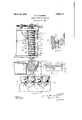
- Figure 1 is a top plan view of a portion of a fodder cutting machine
- Figure 2 is a longitudinal sectional view thereof, and a transverse sectional view of a cooperating feeding roll, taken on a ver tical plane corresponding to line 22 of Figure 1; 1
- Figure 3 is a top plan View (enlarged) of portions of the said machine
- Figure 4 is a sectional view (also enlarged) of portions of some of the parts taken on a vertical plane corresponding to line 4- 1 of Figures 1 and 3;
- Figure 5 is a rear view of the stationary blade of the cutting means of such a machine, and of connected parts.
- the work is fed to the cutting devices usually by feeding rolls having projecting members or teeth moving by the rolls rotation through correspondingly shaped recesses in a stationary element or bar, so that the fodder, while being thus fed, is somewhat compressed to better efiect the cutting thereof.
- the fodder is liable to clog or be so wedged between the rolls teeth and the sides of said recesses as to stop or at least delay or hinder the feeding of the work and the operation of the machine.
- the object of the present invention is to obviate this difiiculty.
- the fodder on the approximately horizontal platform 1 is moved into feedin engagement with the feeding element, the T011 2, which is rotated in its bearings 3 by suitable means as the gear 4. carried In fodder-cutting machines and the like,-
- the feeding element or roll 2 has a plurality of series 7 of work-engaging members or teeth 8.
- the work is somewhat compressed in its feeding movement, between the forward facesl9 of the teeth or members 8 of the element 13, and in such compressed or compacted condition is more effectively operated on by-the cutting means 15 and 16.
- the recesses 20 comprise not only the sides 21 (with which compressingly ;.roll 2 and theupper surface of the bar or cooperate the forward faces 9 of the teeth 8 at their sides 11)'but comprise also another or farther portion spaced away from the teeth 8 sufficiently that the work cannot. wedge between such portion and said teeth, but will be pushedv by the feeding r0112 along the upper surface 14 of the bar or ele- 18; Such space is provided,- inthe con I of the bar 13.
- both sides 11 of the teeth 8 pass in the rotation of the roll 2 so near the inclined sides 21 of recesses in the bar 13, and the outer extremities of these teeth pass so near 'the bottom of the recesses (such recesses receiving only one series of teeth), that the compressing action of the teeth on the work c occurs at both sides of the teeths forward faces and at their outer extremities, thus (there being no relieffrom such. compressing action at any point along the edge'of the proximately radial direction (indicated in- 1 i dotted linesv in Figure 5) as to exert a shearrecesses) the result follows that the work frequently Wedges between the compressing agents-the teeth 8 and the-edge of the recesses in the bar 13.
- a-rotatable feeding element having a plurality of axially spaced series of angularly spaced radially extending work-engaging members, the adjacent sides of adjacent, series being outwardly inclined from-each other and the forward surfaces of saidmembers being outwardly and rearwardly inclined relatively to the intersecting radii respectively of said element; an element having-an edge adjacent said feeding ele *ment provided with a serration comprising recesses 1 having sides inclined from each other toward said edge and cooperatlng with the non-adjacent sides of a pair of said series to compress between said elements the work in its feeding movement.
- a rotatable feeding element having a plurality of axially spaced series of angularly spaced radially extending work-engaging members, the adjacent sides of adjacent series being outwardly inclined from each 3.
- a rotatable feeding element having aplurality of axially spaced, series of angularly spaced radially extendingworkengaging members, the adjacent, sides of adjacent series being outwardly inclined from each other and the, forward surfaces :of said members being outwardly and rearwardly inclined relatively tothe intersecting radii respectively of said element;- anjf.
- 1 element having an edge adjacent said feeding element provided with a serration comprising recesses having sides inclined from each other toward saidedge and cooperating with the sides of saidseries to compress between said elements the workin its'feeding move ment, the recesses having concave bottoms spacedfarther from the outer extremities of said members cooperating therewith than the sides of said members are spaced from the adjacent sides of the recesses.
- a rotatable feeding element having angularlyspaced radially extending workengaging members; an element having arecess through which said members pass in the feeding elements rotation, the recess having sides cooperating with said members to compress the work in its feeding movement and having also a bottom portion spaced farther from the outer extremities of said members cooperating therewith than the sides vof said members are spaced from the adjacent sides'of the recess.
Landscapes
- Life Sciences & Earth Sciences (AREA)
- Chemical & Material Sciences (AREA)
- Engineering & Computer Science (AREA)
- Food Science & Technology (AREA)
- Polymers & Plastics (AREA)
- Fodder In General (AREA)
Description
March 20, 1928. 1,663,114 o. B. CLEMENS FODDER CUTTER AND THE LIKE Fi/led Jax s.15, 1927 [NVENTOR OJcaZ B. CZamenJ ATTORNEY Patented Mar. 20, 1928.
OSCAR B. CLEMENS, OF GRAND RAPIDS, MICHIGAN.
vFODDER CUTTER AND THE LIKE.
Application filed January 15, 1927. Serial No. 161,266.
clog or engage in such manner as to stop or.
hinder the feeding thereof.
These and any further objects hereinafter appearing are attained by, and the invention' finds preferable embodiment in, the
mechanism hereinafter particularly described in the body of this specification and illustrated by the accompanying drawings, in which Figure 1 is a top plan view of a portion of a fodder cutting machine;
Figure 2 is a longitudinal sectional view thereof, and a transverse sectional view of a cooperating feeding roll, taken on a ver tical plane corresponding to line 22 of Figure 1; 1
Figure 3 is a top plan View (enlarged) of portions of the said machine;
Figure 4 is a sectional view (also enlarged) of portions of some of the parts taken on a vertical plane corresponding to line 4- 1 of Figures 1 and 3; and
Figure 5 is a rear view of the stationary blade of the cutting means of such a machine, and of connected parts.
the work is fed to the cutting devices usually by feeding rolls having projecting members or teeth moving by the rolls rotation through correspondingly shaped recesses in a stationary element or bar, so that the fodder, while being thus fed, is somewhat compressed to better efiect the cutting thereof.
In such hitherto-known machines, the fodder is liable to clog or be so wedged between the rolls teeth and the sides of said recesses as to stop or at least delay or hinder the feeding of the work and the operation of the machine. The object of the present invention is to obviate this difiiculty.
In the machine illustrated by the accompanying drawings, the fodder on the approximately horizontal platform 1 is moved into feedin engagement with the feeding element, the T011 2, which is rotated in its bearings 3 by suitable means as the gear 4. carried In fodder-cutting machines and the like,-
by the shaft 5 of said element, and is feedingly engaged between this element 2 and a suitable cooperating roll 6. The feeding element or roll 2 has a plurality of series 7 of work-engaging members or teeth 8.
- The several series 7 are axially spaced apart,
side by side, about the periphery of the roll 2'; and the teeth or work-engaging members 8 composing each of the said series are angularly spaced apart, the forward faces 9 of these members 8 extending outwardly v (i. e. from the axis of the roll 2) in a direction inclined relativelyto the radii 10 which vintersect said surfaces respectively; and the adjacent sides 11, 11 of adjacent series 7, 7 of these teeth or members 8 are inclined outwardly from each other; or, in other words, there is an annular groove 12, whose opposite sides (11, 11) incline outwardly from each other, between adjacent series 7, 7 A stationary element 13 having an approximately horizontal upper face 14L receives the fed work from the rolls 2, 6, and has at its rear the stationary cutting edge or blade 15 with which cooperates the movable cutting blade 16 to sever the fodder into. lengths or separate pieces; This element. 13 hasits opposite or forward edge, adjacent the feeding element orroll 2, provided with a serration comprising recesses 20 whose sides 21 are inclined from each other toward said forward edge.
The work is somewhat compressed in its feeding movement, between the forward facesl9 of the teeth or members 8 of the element 13, and in such compressed or compacted condition is more effectively operated on by-the cutting means 15 and 16.
In order to prevent the work in its feeding and compacting movement from being pressed down and wedging between the sides 11 of the teeth or members 8 and the adjacent sides 21 of the recesses 20 (thus clogging or stopping the operation of the machine), the recesses 20 comprise not only the sides 21 (with which compressingly ;.roll 2 and theupper surface of the bar or cooperate the forward faces 9 of the teeth 8 at their sides 11)'but comprise also another or farther portion spaced away from the teeth 8 sufficiently that the work cannot. wedge between such portion and said teeth, but will be pushedv by the feeding r0112 along the upper surface 14 of the bar or ele- 18; Such space is provided,- inthe con I of the bar 13.
In fodder cutting machines hitherto known, both sides 11 of the teeth 8 pass in the rotation of the roll 2 so near the inclined sides 21 of recesses in the bar 13, and the outer extremities of these teeth pass so near 'the bottom of the recesses (such recesses receiving only one series of teeth), that the compressing action of the teeth on the work c occurs at both sides of the teeths forward faces and at their outer extremities, thus (there being no relieffrom such. compressing action at any point along the edge'of the proximately radial direction (indicated in- 1 i dotted linesv in Figure 5) as to exert a shearrecesses) the result follows that the work frequently Wedges between the compressing agents-the teeth 8 and the-edge of the recesses in the bar 13.
Upwardly extending side flanges 30, guide and retain the work against sidewise displacement. Inasmuch as Y the blades 16 "are preferably carried by a head 31 on the rotatable shaft 82 and extend in such apin'g action on the work between the blades 15, 16, the tendency of the blade 16 to push "thefwork laterally toward the flange 30 and thus 'Wedgethe same between the blade 16 and the rearen'd 33 of said flange is resisted by said flange 30.
The invention being intended to be pointed out in the following claims, is not to be limited to or by details of construction of any'particular embodimentthereof illustrated b the accompanying drawings or hereinbefore described.
I claim:
1. In mechanism of the character described a-rotatable feeding element having a plurality of axially spaced series of angularly spaced radially extending work-engaging members, the adjacent sides of adjacent, series being outwardly inclined from-each other and the forward surfaces of saidmembers being outwardly and rearwardly inclined relatively to the intersecting radii respectively of said element; an element having-an edge adjacent said feeding ele *ment provided with a serration comprising recesses 1 having sides inclined from each other toward said edge and cooperatlng with the non-adjacent sides of a pair of said series to compress between said elements the work in its feeding movement.
2. In mechanism of the character described: a rotatable feeding element having a plurality of axially spaced series of angularly spaced radially extending work-engaging members, the adjacent sides of adjacent series being outwardly inclined from each 3. In mechanism -of the character 'vde-i scribed: a rotatable feeding element having aplurality of axially spaced, series of angularly spaced radially extendingworkengaging members, the adjacent, sides of adjacent series being outwardly inclined from each other and the, forward surfaces :of said members being outwardly and rearwardly inclined relatively tothe intersecting radii respectively of said element;- anjf. 1 element having an edge adjacent said feeding element provided with a serration comprising recesses having sides inclined from each other toward saidedge and cooperating with the sides of saidseries to compress between said elements the workin its'feeding move ment, the recesses having concave bottoms spacedfarther from the outer extremities of said members cooperating therewith than the sides of said members are spaced from the adjacent sides of the recesses.
4. In mechanism of the character described: a rotatable feeding element having angularlyspaced radially extending workengaging members; an element having arecess through which said members pass in the feeding elements rotation, the recess having sides cooperating with said members to compress the work in its feeding movement and having also a bottom portion spaced farther from the outer extremities of said members cooperating therewith than the sides vof said members are spaced from the adjacent sides'of the recess.
In testimony whereof Ihave hereunto set my hand at Grand Rapids, Michigan, this 11th day ofJanuary, 1927.
OSCAR B. CLEMENS.
Priority Applications (1)
| Application Number | Priority Date | Filing Date | Title |
|---|---|---|---|
| US161266A US1663114A (en) | 1927-01-15 | 1927-01-15 | Fodder cutter and the like |
Applications Claiming Priority (1)
| Application Number | Priority Date | Filing Date | Title |
|---|---|---|---|
| US161266A US1663114A (en) | 1927-01-15 | 1927-01-15 | Fodder cutter and the like |
Publications (1)
| Publication Number | Publication Date |
|---|---|
| US1663114A true US1663114A (en) | 1928-03-20 |
Family
ID=22580506
Family Applications (1)
| Application Number | Title | Priority Date | Filing Date |
|---|---|---|---|
| US161266A Expired - Lifetime US1663114A (en) | 1927-01-15 | 1927-01-15 | Fodder cutter and the like |
Country Status (1)
| Country | Link |
|---|---|
| US (1) | US1663114A (en) |
Cited By (1)
| Publication number | Priority date | Publication date | Assignee | Title |
|---|---|---|---|---|
| US2457951A (en) * | 1942-05-11 | 1949-01-04 | Deere Mfg Co | Rotary feed cutter with shear bar arranged on a chord |
-
1927
- 1927-01-15 US US161266A patent/US1663114A/en not_active Expired - Lifetime
Cited By (1)
| Publication number | Priority date | Publication date | Assignee | Title |
|---|---|---|---|---|
| US2457951A (en) * | 1942-05-11 | 1949-01-04 | Deere Mfg Co | Rotary feed cutter with shear bar arranged on a chord |
Similar Documents
| Publication | Publication Date | Title |
|---|---|---|
| DE2907712C2 (en) | Grinding disc for fibrous, preferably vegetable, grist | |
| US1663114A (en) | Fodder cutter and the like | |
| US2299248A (en) | Log chipper | |
| US2297782A (en) | Crushing machine | |
| US2247665A (en) | Chipper | |
| US1946763A (en) | Rock-crushing machine | |
| DE7148062U (en) | STRIPPING DEVICE FOR MEAT SKINNING OR DEMANDING MACHINES | |
| US683826A (en) | Cotton-seed huller. | |
| DE754112C (en) | Extraction and loading machine for underground longwall mining | |
| US3509A (en) | Improvement in sausage-meat cutters | |
| US3262476A (en) | Means for obtaining smooth wood flakes while producing a flat surface wood | |
| AT104780B (en) | Bacon dicing machine. | |
| US4371A (en) | Straw-cutter | |
| US257966A (en) | Henry midwood | |
| US1932166A (en) | Thrust bearings for chippers | |
| US1708442A (en) | Multiple-groover machine | |
| DE1156267B (en) | Machine for chopping essentially cube-shaped pieces of minced fruit or similar products | |
| US1099221A (en) | Power log-loader. | |
| DE632058C (en) | Jaw crusher | |
| DE829947C (en) | Milling head for whitewashing round wood | |
| US13839A (en) | Mill for grinding | |
| DE20002764U1 (en) | Slicer for fruits and vegetables | |
| DE358950C (en) | Peat machine u. Like. With one or more screws, a perforated disc and circling knives in front of it | |
| DE517151C (en) | Machine for trimming the heel ends of soles | |
| US1333882A (en) | sumner |