US1650737A - Fitting - Google Patents
Fitting Download PDFInfo
- Publication number
- US1650737A US1650737A US129705A US12970526A US1650737A US 1650737 A US1650737 A US 1650737A US 129705 A US129705 A US 129705A US 12970526 A US12970526 A US 12970526A US 1650737 A US1650737 A US 1650737A
- Authority
- US
- United States
- Prior art keywords
- fitting
- coating
- pipe
- layer
- projections
- Prior art date
- Legal status (The legal status is an assumption and is not a legal conclusion. Google has not performed a legal analysis and makes no representation as to the accuracy of the status listed.)
- Expired - Lifetime
Links
- 239000011248 coating agent Substances 0.000 description 15
- 238000000576 coating method Methods 0.000 description 15
- 239000000463 material Substances 0.000 description 6
- 238000000034 method Methods 0.000 description 3
- 239000010425 asbestos Substances 0.000 description 2
- 238000001035 drying Methods 0.000 description 2
- 238000010438 heat treatment Methods 0.000 description 2
- 229910052895 riebeckite Inorganic materials 0.000 description 2
- 238000010276 construction Methods 0.000 description 1
- 230000000875 corresponding effect Effects 0.000 description 1
- 238000005336 cracking Methods 0.000 description 1
- 238000005304 joining Methods 0.000 description 1
- 238000004519 manufacturing process Methods 0.000 description 1
Images
Classifications
-
- F—MECHANICAL ENGINEERING; LIGHTING; HEATING; WEAPONS; BLASTING
- F16—ENGINEERING ELEMENTS AND UNITS; GENERAL MEASURES FOR PRODUCING AND MAINTAINING EFFECTIVE FUNCTIONING OF MACHINES OR INSTALLATIONS; THERMAL INSULATION IN GENERAL
- F16L—PIPES; JOINTS OR FITTINGS FOR PIPES; SUPPORTS FOR PIPES, CABLES OR PROTECTIVE TUBING; MEANS FOR THERMAL INSULATION IN GENERAL
- F16L59/00—Thermal insulation in general
- F16L59/14—Arrangements for the insulation of pipes or pipe systems
- F16L59/16—Arrangements specially adapted to local requirements at flanges, junctions, valves or the like
Definitions
- This invention relates to a fitting for a pipe line which it is desired to insulate, as by a coatingofasbestos material.
- fitting as employed in this application, I refer to those devices for joining together a plurality of pipes which are out of axial alinement with each other. This is the generally accepted meaning of the word in the trade.
- Straight lengths of pipe have been coated with asbestos by known methods and in an eiiicient manner, but in coating a fitting such as an elbow or a T difficulty has been experienced. It is the present practice to coat the fittings by plastering the material 5 thereon.
- the exterior of the fitting is smooth and furnishes a poor bond for the material. It has been customary to wire the fitting or to wrap it with twine or other material before applying the coating thereto.
- the first layer has to be given time to dry and then it is necessary to return later to apply the second layer.
- the coating during drying will shrink and crack.
- a further object of my invention is to provide a fitting which shall retain a coating thereon and prevent its cracking or shrinking.
- a still further object of my invention is to provide a fitting which shall not only perform the above functions, but shall also provide a grip for a wrench or other tool which the ordinary fittings do not provide.
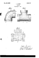
- Figure 1 is an elevation of an elbow fitting constructed according to my invention.
- FIG. 2 is an elevation of a T fitting having my invention embodied therein.
- FIG. 3 is an elevation of a T' fitting showing another form which my invention may take.
- elbow 1 having the two branches 2 and 3, which are joined together by the curved portion 4, and which have the usual flanges to connect the fitting to pipes.
- the curved portion 4 is the part to which it is very diificult to apply the coating.
- a coating of asbestos material is about one-half inch thick when applied to one inch pipe, and therefore it is diflicult to make such a thick coating adhere to the rounded surface of the fitting.
- the same is true to a great extent of the coating which must be applied to the flanges 5 and 6 at the ends of the branches 2 and 3.
- the first layer has been held on the pipeby wiring or the like, which will corrode in time and cause loosening of the coating.
- I provide a plurality of projections 7 extending outwardly from the surface of the fitting.
- These projections may be formed in a variety of ways, but I have shown them here as comprising a plurality of pointed lugs cast integral with the fitting, a construction which I have found to be very eflicient. The number and arrangement of these lugs may be varied as desired.
- Figure 3 I have shown a 'l' fitting 10 having its outer surface formed with a pin-- rality of corrugations 11, preferably made in the wavy form shown.
- the gist of my invention resides in a fitting having the outer surface provided with outwardly extending projections. These may be formed in any way so long as the roughened surface is provided to hold the coating in place and to prevent its shrinkage. It will be noted that the projections are relatively short so as to be completely embedded in the covering or coating and completely covered thereby. I have found that with my invention a coating maybe applied very rapidly to a fitting and by a helper instead of by more skilled labor. All that is necessary to do is to apply the plastic material with the hand and smooth it over with a trowel.
- fittings are provided with flanges such as shown in the drawing and these flanges are provided with screw-threads on their interior, which threads are adapted to engage correspond-- ing threads on the exterior of pipes, the ends of which are received within the flanges.
- a pipe fit- 30 ting adapted to join together a plurality of pipes out of axial alinement with each other
- said fitting having its outer surface pro
Landscapes
- Engineering & Computer Science (AREA)
- General Engineering & Computer Science (AREA)
- Mechanical Engineering (AREA)
- Protection Of Pipes Against Damage, Friction, And Corrosion (AREA)
Description
Nov. 29, 1927.
J. J. QUHN WWWG Filed Mm 19% ATTORNEY Patented Nov. 29, 1927.
UNITED STATES I 1,650,737 PATENT OFFICE.
JOHN J. QUINN, OF ENGLEWOOD, NEW JERSEY, ASSIGNOR, BY MESNE ASSIGNMENTS, OF ONE-HALF TO JEREMIAH J. LANE, OF ENGLEWOOD, NEW JERSEY.
FITTING.
Application filed August 17, 1926.
This invention relates to a fitting for a pipe line which it is desired to insulate, as by a coatingofasbestos material. By the word fitting as employed in this application, I refer to those devices for joining together a plurality of pipes which are out of axial alinement with each other. This is the generally accepted meaning of the word in the trade. Straight lengths of pipe have been coated with asbestos by known methods and in an eiiicient manner, but in coating a fitting such as an elbow or a T difficulty has been experienced. It is the present practice to coat the fittings by plastering the material 5 thereon. The exterior of the fitting is smooth and furnishes a poor bond for the material. It has been customary to wire the fitting or to wrap it with twine or other material before applying the coating thereto.
Then it has been necessary to apply the coating in two layers. The first layer has to be given time to dry and then it is necessary to return later to apply the second layer.
The coating during drying will shrink and crack. In order to hasten the drying of the first layer it has been customary to heat the pipe as by building a fire in the heating plant of which the fitting forms a part.
It is the object of my invention to provide a fitting of novel and improved form which shall avoid the expensive procedure outlined above and which shall permit the coating to be applied in one layer and to be applied rapidly without the heating of the pipe.
A further object of my invention is to provide a fitting which shall retain a coating thereon and prevent its cracking or shrinking.
A still further object of my invention is to provide a fitting which shall not only perform the above functions, but shall also provide a grip for a wrench or other tool which the ordinary fittings do not provide.
a In the accompanying drawings in which I have shown a selected embodiment of my invention Figure 1 is an elevation of an elbow fitting constructed according to my invention.
Figure 2 is an elevation of a T fitting having my invention embodied therein.
Figure 3 is an elevation of a T' fitting showing another form which my invention may take.
Referring now to the drawing in detail and more particularly to Figure 1, I have shown therein a fitting in the form of an Serial N0. 129,705.
elbow 1 having the two branches 2 and 3, which are joined together by the curved portion 4, and which have the usual flanges to connect the fitting to pipes. The curved portion 4 is the part to which it is very diificult to apply the coating. A coating of asbestos material is about one-half inch thick when applied to one inch pipe, and therefore it is diflicult to make such a thick coating adhere to the rounded surface of the fitting. The same is true to a great extent of the coating which must be applied to the flanges 5 and 6 at the ends of the branches 2 and 3. As stated above, it has been customary to apply one layer, dry the same, and then apply the second layer to form the required thickness. The first layer has been held on the pipeby wiring or the like, which will corrode in time and cause loosening of the coating.
In order to avoid the above difficulty and the others mentioned, I provide a plurality of projections 7 extending outwardly from the surface of the fitting. These projections may be formed in a variety of ways, but I have shown them here as comprising a plurality of pointed lugs cast integral with the fitting, a construction which I have found to be very eflicient. The number and arrangement of these lugs may be varied as desired.
In Figure 2 I have shown a T fi ting formed of two intersecting branches 8 and 9, and having applied to the outer surface thereof the pointed lugs 7.
In Figure 3 I have shown a 'l' fitting 10 having its outer surface formed with a pin-- rality of corrugations 11, preferably made in the wavy form shown.
Other forms may suggest themselves to those skilled in the art, but the gist of my invention resides in a fitting having the outer surface provided with outwardly extending projections. These may be formed in any way so long as the roughened surface is provided to hold the coating in place and to prevent its shrinkage. It will be noted that the projections are relatively short so as to be completely embedded in the covering or coating and completely covered thereby. I have found that with my invention a coating maybe applied very rapidly to a fitting and by a helper instead of by more skilled labor. All that is necessary to do is to apply the plastic material with the hand and smooth it over with a trowel.
The entire work is done in a very short time and it is not necessary for the laborer to return at a later time to finish the job. The saving of labor has been found to be approximately 50% of the amount of labor required by the older methods in prior use.
The roughened surface formed by the projections will not only hold the coating in place and prevent shrinkage thereof, but will also furnish a grip for a wrench or other tool, thus greatly aiding the ease with which the fitting is installed. As is well known to those skilled in the art fittings are provided with flanges such as shown in the drawing and these flanges are provided with screw-threads on their interior, which threads are adapted to engage correspond-- ing threads on the exterior of pipes, the ends of which are received within the flanges. By this means two or more pipes are joined together by a fitting. The
roughened surface on my fitting furnishes a convenient grip for tightening of a fitting upon a. pipe to which it ma be applied.
I am aware that various cianges in de- 25 tails may be made Within the scope of my invention and I do not intend to limit myself except by the appendedclaim.
I claim:
As an article of manufacture, a pipe fit- 30 ting adapted to join together a plurality of pipes out of axial alinement with each other,
said fitting having its outer surface pro;-
vided With relatively short projections adapted to bind a heat resisting plastic 3 JOHN J. QUINN.
Priority Applications (1)
| Application Number | Priority Date | Filing Date | Title |
|---|---|---|---|
| US129705A US1650737A (en) | 1926-08-17 | 1926-08-17 | Fitting |
Applications Claiming Priority (1)
| Application Number | Priority Date | Filing Date | Title |
|---|---|---|---|
| US129705A US1650737A (en) | 1926-08-17 | 1926-08-17 | Fitting |
Publications (1)
| Publication Number | Publication Date |
|---|---|
| US1650737A true US1650737A (en) | 1927-11-29 |
Family
ID=22441199
Family Applications (1)
| Application Number | Title | Priority Date | Filing Date |
|---|---|---|---|
| US129705A Expired - Lifetime US1650737A (en) | 1926-08-17 | 1926-08-17 | Fitting |
Country Status (1)
| Country | Link |
|---|---|
| US (1) | US1650737A (en) |
Cited By (4)
| Publication number | Priority date | Publication date | Assignee | Title |
|---|---|---|---|---|
| US2809365A (en) * | 1954-09-07 | 1957-10-08 | Amp Inc | Electrical connector |
| US2876154A (en) * | 1954-05-14 | 1959-03-03 | Reflin Co | Means and methods for attaching connectors to plastic pipe ends |
| US6764102B2 (en) * | 2002-03-22 | 2004-07-20 | Smc Kabushiki Kaisha | Tube joint |
| USD676942S1 (en) * | 2012-01-11 | 2013-02-26 | Bill Kluss | Tee pipe coupling |
-
1926
- 1926-08-17 US US129705A patent/US1650737A/en not_active Expired - Lifetime
Cited By (4)
| Publication number | Priority date | Publication date | Assignee | Title |
|---|---|---|---|---|
| US2876154A (en) * | 1954-05-14 | 1959-03-03 | Reflin Co | Means and methods for attaching connectors to plastic pipe ends |
| US2809365A (en) * | 1954-09-07 | 1957-10-08 | Amp Inc | Electrical connector |
| US6764102B2 (en) * | 2002-03-22 | 2004-07-20 | Smc Kabushiki Kaisha | Tube joint |
| USD676942S1 (en) * | 2012-01-11 | 2013-02-26 | Bill Kluss | Tee pipe coupling |
Similar Documents
| Publication | Publication Date | Title |
|---|---|---|
| US1842298A (en) | Underground pipe line | |
| US1650737A (en) | Fitting | |
| US2405330A (en) | Insulating structure | |
| US2656902A (en) | Insulated heat conducting unit | |
| US3480493A (en) | Method and apparatus for spray foam insulating a pipe | |
| US2315895A (en) | Concrete construction | |
| US3044915A (en) | Method and appliance for heat insulation | |
| US2209547A (en) | Insulated pipe | |
| US852997A (en) | Joint for sewer and like pipes. | |
| US3228425A (en) | Concrete pipe construction | |
| US1013291A (en) | Method of applying pipe-covering. | |
| US2011452A (en) | Manufacturing paper tubes and the like | |
| JPS6212952Y2 (en) | ||
| US1344321A (en) | Pipe-line | |
| US2405567A (en) | Pipe joint | |
| CN208202211U (en) | Complete facing fills the processing structure of Sunken wire tube after wall | |
| US1853698A (en) | Method of and means for coupling fiber conduits | |
| US2473875A (en) | Tubes, pipes, and the like | |
| US1868881A (en) | Method of laying multiple fiber conduit | |
| DE2200606A1 (en) | METAL PIPE COVERED WITH PLASTIC FOR INCREASED EXTERNAL PRESSURE | |
| US1439653A (en) | Composite heat insulation for piping | |
| CN210920383U (en) | Direct-buried heat-insulation steel pipe | |
| JPS5874984A (en) | Method of treating pipe | |
| CN210013204U (en) | Fireproof polyester plastic grille | |
| RU2121619C1 (en) | Method of banding defective section of operating pipe line |