US1853698A - Method of and means for coupling fiber conduits - Google Patents
Method of and means for coupling fiber conduits Download PDFInfo
- Publication number
- US1853698A US1853698A US214067A US21406727A US1853698A US 1853698 A US1853698 A US 1853698A US 214067 A US214067 A US 214067A US 21406727 A US21406727 A US 21406727A US 1853698 A US1853698 A US 1853698A
- Authority
- US
- United States
- Prior art keywords
- conduit
- coupling
- sections
- fiber
- bolts
- Prior art date
- Legal status (The legal status is an assumption and is not a legal conclusion. Google has not performed a legal analysis and makes no representation as to the accuracy of the status listed.)
- Expired - Lifetime
Links
- 230000008878 coupling Effects 0.000 title description 16
- 238000010168 coupling process Methods 0.000 title description 16
- 238000005859 coupling reaction Methods 0.000 title description 16
- 239000000835 fiber Substances 0.000 title description 14
- 238000000034 method Methods 0.000 title description 3
- 239000000463 material Substances 0.000 description 13
- 239000002253 acid Substances 0.000 description 3
- 150000007513 acids Chemical class 0.000 description 3
- 239000010426 asphalt Substances 0.000 description 3
- 239000002657 fibrous material Substances 0.000 description 3
- 239000012530 fluid Substances 0.000 description 3
- 238000012856 packing Methods 0.000 description 3
- 239000004568 cement Substances 0.000 description 2
- 239000011248 coating agent Substances 0.000 description 2
- 238000000576 coating method Methods 0.000 description 2
- 238000004519 manufacturing process Methods 0.000 description 2
- 229920006395 saturated elastomer Polymers 0.000 description 2
- XLYOFNOQVPJJNP-UHFFFAOYSA-N water Substances O XLYOFNOQVPJJNP-UHFFFAOYSA-N 0.000 description 2
- 238000004078 waterproofing Methods 0.000 description 2
- 208000027418 Wounds and injury Diseases 0.000 description 1
- 239000000956 alloy Substances 0.000 description 1
- 229910045601 alloy Inorganic materials 0.000 description 1
- 150000001875 compounds Chemical class 0.000 description 1
- 230000007797 corrosion Effects 0.000 description 1
- 238000005260 corrosion Methods 0.000 description 1
- 230000006378 damage Effects 0.000 description 1
- 230000002542 deteriorative effect Effects 0.000 description 1
- 230000003467 diminishing effect Effects 0.000 description 1
- 229920001971 elastomer Polymers 0.000 description 1
- 208000014674 injury Diseases 0.000 description 1
- 238000002844 melting Methods 0.000 description 1
- 239000002184 metal Substances 0.000 description 1
- 238000012986 modification Methods 0.000 description 1
- 230000004048 modification Effects 0.000 description 1
- 239000004033 plastic Substances 0.000 description 1
- 239000011347 resin Substances 0.000 description 1
- 229920005989 resin Polymers 0.000 description 1
- 239000002904 solvent Substances 0.000 description 1
- 239000000126 substance Substances 0.000 description 1
- 239000002982 water resistant material Substances 0.000 description 1
- 239000002023 wood Substances 0.000 description 1
Images
Classifications
-
- F—MECHANICAL ENGINEERING; LIGHTING; HEATING; WEAPONS; BLASTING
- F16—ENGINEERING ELEMENTS AND UNITS; GENERAL MEASURES FOR PRODUCING AND MAINTAINING EFFECTIVE FUNCTIONING OF MACHINES OR INSTALLATIONS; THERMAL INSULATION IN GENERAL
- F16L—PIPES; JOINTS OR FITTINGS FOR PIPES; SUPPORTS FOR PIPES, CABLES OR PROTECTIVE TUBING; MEANS FOR THERMAL INSULATION IN GENERAL
- F16L13/00—Non-disconnectable pipe joints, e.g. soldered, adhesive, or caulked joints
Definitions
- This invention relates to the coupling together of sections of fiber tubing or conduit in end-to-end relationship, the coupling being made in such a way as to provide a relatively strong, stifi joint.
- conduit made ofpaper pulp which is formed into a wet sheet and rolled up under pressure so that the fibers are compacted'and closely interfelted. W hen the tube is dried, the thorough interfelting results in a conduit having walls of relatively great strength and stiffness. The conduit may then r be impregnated with pitch, asphalt or other equivalent or suitable compounds.
- the impregnated conduit may also be coated; with gilsonite, blown asphalt or other suitable material to make it thoroughly waterproof.
- the resulting product is relatively light, strong, and inexpensive, and is suitable for many industrial uses. Owing to its electric insulatingqualities, it is useful also as power make a strong water-tight joint without diminishing the electric insulating properties of the conduit.
- a suitable coupling is provided having these desired characteristics and furthermore being resistant to corrosion.
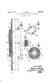
- Figure l is an elevation, partly in section, of a coupling embodying my invention.
- Figure 2 is a transverse section on the line 2-2 of Figure 1.'
- Figure 3 is a fragmentary section showing a slightly modified joint.
- Figure 4 is a ring element which may be used with the coupling.
- 10 represents asection offiber conduit of any desired kind.
- a flange or collar of substantial length may be formed, as for example, by tightly fitting thereover short sections 11 of similar conduit of larger diameters.
- One or more of such short sections may be concentrically arranged upon one another until the desired thickness of flange or collar. is built up.
- three sections 11 are shown on the end portion of each conduit section 10 forming a flange or collar having a substantial thickness and a length almost twice the di ameter of the conduit section 10, but more or less sections 11' may be secured to the end portion of the conduit and to each other by any desired means.
- a plurality of radially extending pegs 12 or similar fastening elements may be used, such pegs being preferably of wood or other fibrous material and being embedded in the sections 10 and 11 in such a way as toanchor them together into a unitary flange. It is usually desirable to waterproof fiber conduit in order to make it resistant to the deteriorating action of moisture and to make it useful as piping for fluids.
- the sections 10 and 11 maybe impregnated with water-resistant saturant of any desired or convenient kind, such as low-melting point asphalt,
- the sa-turant may also be a fluid solution of the above or equivalent waterproofing materials,
- the'solvent being of such a nature as to be i removable after the fibrous body has been saturated.
- he flanges are provided with longitudinally extending perforations or bores of a size to receive suitable bolts 13 in closely fitting engagement.
- bores are preferably arranged symmetrically about the axis of the conduit so that when two end portions are placed in abutting end-to-end relation as shown in Figure 1, the bores through the abutting flanges may be brought into registry so that the bolts 13 can be passed through both the abutting flanges.
- the bolts are preferably of alength to extend beyond the remote faces of the flanges when inserted therein, the projecting ends of the bolts being preferably threaded to receive suitable nuts 14:.
- I may provide cap nuts of a noncorroding alloy so as to protect the bolts from corrosi n by moisture or acids which may be present under some conditions of use.
- I may coat all the free surfaces thereof, within and without, with a suitable waterproofing or acid-resisting material such as for example gilsonite, such coating being indicated as 15.
- a suitable waterproofing or acid-resisting material such as for example gilsonite, such coating being indicated as 15.
- I may insert a gasket 16 of rubber or other suitable packing material between the abutting end faces of the flanges.
- I may apply a layer 17 of gilsonite. cement, or other plastic packing material suitable for the purpose.
- rings may be of any desired form or material.
- I may use a split metal ring 18 comprising two or more parts, an end of each part being offset as at 19 so as to provide a plane face for the ring to bear against the end face of th flange.
- the ring is perforated as at 20, these perforations being arranged to register with the bores extending through the flange.
- the rings 18 may be of any hard material, preferably a material which is non-corroding.
- a coupling for fiber conduit comprising, in combination with a pair of sections of fiber conduit in abutting end-to-end relation, a fiber collar of substantial length secured on each of the abutting end portions, said collars each having an end face flush with the end of its conduit section, means for securing said collars to said end portions comprising radially extending fiber fastening elements embedded in the conduits and collars, water-resistant material permeating said fibrous conduit, collars, and fastening elements, a ring of packing material between the opposed faces of said collars and conduit sections, a plurality of bolts embedded in said collars and extending therethrough to the mutually remote ends thereof parallel to the axis of the collars, nuts on the ends of said bolts, and a coating of waterproof material covering the free surfaces of said sections and collars.
- a fiber conduit section having a fiber collar of substantial length on an end portion thereof, and means for fastening said collar to said end portion, said fastening means comprising pegs of fibrous material embedded in said collar and end portion, said collar being provided with bores extending from end to end thereof.
Landscapes
- Engineering & Computer Science (AREA)
- General Engineering & Computer Science (AREA)
- Mechanical Engineering (AREA)
- Flanged Joints, Insulating Joints, And Other Joints (AREA)
Description
April 12, 1932. w H. PARKER 1,853,698
' METHOD OF AND MEANS FOR COUPLING FIBER CONDUITS Filed Aug. 19. 1927 Patented Apr. 7 12, 1932 UNIT s'resi ATENT FFI'CE HOWARD PARKER, 01 BERLIN, NEW HAMPSHIRE, ASSIGNOR TO BROWN COMPANY, OF BERLIN, NEW HAMPSHIRE, A CORPORATION OF MAINE 7 METHOD OF AND M EANS FOR COUPLING FIBER CONDUITS Application filed August 19, um. Serial No. 214,067.
' This invention relates to the coupling together of sections of fiber tubing or conduit in end-to-end relationship, the coupling being made in such a way as to provide a relatively strong, stifi joint. I It is an object of the invention to provide a coupling which will have a minimum of weight and bulk consistent with requisite strength and stiffness, which will be simple andinexpensive,-which will be easy to manipulate, which will be-highly resistant to corrosive actionof acids or other'substances in .which the coupling may be submerged, and which will have electric insulating properties not inferior to those of the conduit itself.
' While not necessarily limited to any par:
ticular kind of fiber conduit,'my invention relates especially to conduit made ofpaper pulp which is formed into a wet sheet and rolled up under pressure so that the fibers are compacted'and closely interfelted. W hen the tube is dried, the thorough interfelting results in a conduit having walls of relatively great strength and stiffness. The conduit may then r be impregnated with pitch, asphalt or other equivalent or suitable compounds.
This treatment hardens the walls of the conduit and renders themwa'ter-resistant. The impregnated conduit may also be coated; with gilsonite, blown asphalt or other suitable material to make it thoroughly waterproof. The resulting product is relatively light, strong, and inexpensive, and is suitable for many industrial uses. Owing to its electric insulatingqualities, it is useful also as power make a strong water-tight joint without diminishing the electric insulating properties of the conduit. By my invention, a suitable coupling is provided having these desired characteristics and furthermore being resistant to corrosion.
For a more complete understanding of the invention, reference may be had to the disclosure thereof in the following description and on the drawings, of which,
Figure l is an elevation, partly in section, of a coupling embodying my invention.
Figure 2 is a transverse section on the line 2-2 of Figure 1.'
Figure 3 is a fragmentary section showing a slightly modified joint.
Figure 4 is a ring element which may be used with the coupling.
7 Referring to the drawings in detail, 10 represents asection offiber conduit of any desired kind. On the end portions of each section a flange or collar of substantial length may be formed, as for example, by tightly fitting thereover short sections 11 of similar conduit of larger diameters. One or more of such short sections may be concentrically arranged upon one another until the desired thickness of flange or collar. is built up. In Figure 1, three sections 11 are shown on the end portion of each conduit section 10 forming a flange or collar having a substantial thickness and a length almost twice the di ameter of the conduit section 10, but more or less sections 11' may be secured to the end portion of the conduit and to each other by any desired means. As shown, a plurality of radially extending pegs 12 or similar fastening elements may be used, such pegs being preferably of wood or other fibrous material and being embedded in the sections 10 and 11 in such a way as toanchor them together into a unitary flange. It is usually desirable to waterproof fiber conduit in order to make it resistant to the deteriorating action of moisture and to make it useful as piping for fluids. To this end, the sections 10 and 11 maybe impregnated with water-resistant saturant of any desired or convenient kind, such as low-melting point asphalt,
pitch, resin or other equivalent, which can be rendered relatively fluid at temperatures sufficiently low to avoid injury'to the fibrous material of which the conduit is made. The sa-turant may also be a fluid solution of the above or equivalent waterproofing materials,
' the'solvent being of such a nature as to be i removable after the fibrous body has been saturated. I prefer, however, to assemble and fix the flange or collar on the end of the conduit section before the material is treated in saturant. After the short sections 11 have been secured in place with the pegs 12, the whole structure including the conduit 10, the flange and the pegs 12 may then be saturated together, this treatment serving to cement the separate parts together and thus to lend additional ength to the built-up structure. he flanges are provided with longitudinally extending perforations or bores of a size to receive suitable bolts 13 in closely fitting engagement. These bores are preferably arranged symmetrically about the axis of the conduit so that when two end portions are placed in abutting end-to-end relation as shown in Figure 1, the bores through the abutting flanges may be brought into registry so that the bolts 13 can be passed through both the abutting flanges. The bolts are preferably of alength to extend beyond the remote faces of the flanges when inserted therein, the projecting ends of the bolts being preferably threaded to receive suitable nuts 14:. As shown, I may provide cap nuts of a noncorroding alloy so as to protect the bolts from corrosi n by moisture or acids which may be present under some conditions of use. In order to add further protection to the conduit sections and flanges, I may coat all the free surfaces thereof, within and without, with a suitable waterproofing or acid-resisting material such as for example gilsonite, such coating being indicated as 15. In coupling together the ends of two sections of conduit, I may insert a gasket 16 of rubber or other suitable packing material between the abutting end faces of the flanges. Instead of a gasket 16, however, I may apply a layer 17 of gilsonite. cement, or other plastic packing material suitable for the purpose. After bringing the ends of the conduit sections together with the flange bores in registry, bolts 13 are inserted in thebores and cap nuts 14 are screwed on the ends of the bolts. In order to protect the remote end faces of the flanges from the nuts 14 and to provide a better bearing surface for the nuts, 1 may place on the outer end faces of the flanges suitable rings to act as washers for the nuts 14. Such rings may be of any desired form or material. As illustrated in Figure 4, I may use a split metal ring 18 comprising two or more parts, an end of each part being offset as at 19 so as to provide a plane face for the ring to bear against the end face of th flange. The ring is perforated as at 20, these perforations being arranged to register with the bores extending through the flange. The rings 18 may be of any hard material, preferably a material which is non-corroding. I have thus provided a coupling for sections of fiber conduit which is extremely simple and easy to manufacture, but which is also substantial, strong and efficient. The substantial length of the flanges or collars, which is considerably more than the diameter of the conduit in the coupling illustrated in Figure 1, and the correspondng length of the bolts 13 which are preferably embedded snugly in the material of the collars, provide a structure whereby the stiffness of the bolts is utilized to stiffen the joint as a whole afterthe manner of splints. By utilizing cap nuts of non-corroding material, the coupling is easily made proof against being attacked by water or acids such as are found in mines or factories where the conduit may be used. The coupling hereinbefore described provides an effective solution of the problem of how successfully to join together sections of conduit into a continuous line in a practical, efiicient and economical manner. I
Having thus described certain embodiments of this invention, it should be evident to those skilled in the art that various changes and modifications may be made therein with out departing from its spirit or scope as defined by the appended claims.
I claim l. A coupling for fiber conduitcomprising, in combination with a pair of sections of fiber conduit in abutting end-to-end relation, a fiber collar of substantial length secured on each of the abutting end portions, said collars each having an end face flush with the end of its conduit section, means for securing said collars to said end portions comprising radially extending fiber fastening elements embedded in the conduits and collars, water-resistant material permeating said fibrous conduit, collars, and fastening elements, a ring of packing material between the opposed faces of said collars and conduit sections, a plurality of bolts embedded in said collars and extending therethrough to the mutually remote ends thereof parallel to the axis of the collars, nuts on the ends of said bolts, and a coating of waterproof material covering the free surfaces of said sections and collars.
2. As a new article of manufacture, a fiber conduit section having a fiber collar of substantial length on an end portion thereof, and means for fastening said collar to said end portion, said fastening means comprising pegs of fibrous material embedded in said collar and end portion, said collar being provided with bores extending from end to end thereof.
In testimony whereof I have aflixed my signature. 4
HOWVARD PARKER.
Priority Applications (1)
| Application Number | Priority Date | Filing Date | Title |
|---|---|---|---|
| US214067A US1853698A (en) | 1927-08-19 | 1927-08-19 | Method of and means for coupling fiber conduits |
Applications Claiming Priority (1)
| Application Number | Priority Date | Filing Date | Title |
|---|---|---|---|
| US214067A US1853698A (en) | 1927-08-19 | 1927-08-19 | Method of and means for coupling fiber conduits |
Publications (1)
| Publication Number | Publication Date |
|---|---|
| US1853698A true US1853698A (en) | 1932-04-12 |
Family
ID=22797635
Family Applications (1)
| Application Number | Title | Priority Date | Filing Date |
|---|---|---|---|
| US214067A Expired - Lifetime US1853698A (en) | 1927-08-19 | 1927-08-19 | Method of and means for coupling fiber conduits |
Country Status (1)
| Country | Link |
|---|---|
| US (1) | US1853698A (en) |
Cited By (4)
| Publication number | Priority date | Publication date | Assignee | Title |
|---|---|---|---|---|
| US3160425A (en) * | 1960-12-22 | 1964-12-08 | Victor B Sinnott | Anti-root sewer pipe liner |
| US3402945A (en) * | 1967-04-24 | 1968-09-24 | Bowser Inc | Adjustable liquid connector |
| US5330236A (en) * | 1992-10-02 | 1994-07-19 | Aerofit Products, Inc. | Composite tube fitting |
| US20090087259A1 (en) * | 2007-09-27 | 2009-04-02 | Bettinger David S | Robust Hybrid Structural Joints |
-
1927
- 1927-08-19 US US214067A patent/US1853698A/en not_active Expired - Lifetime
Cited By (4)
| Publication number | Priority date | Publication date | Assignee | Title |
|---|---|---|---|---|
| US3160425A (en) * | 1960-12-22 | 1964-12-08 | Victor B Sinnott | Anti-root sewer pipe liner |
| US3402945A (en) * | 1967-04-24 | 1968-09-24 | Bowser Inc | Adjustable liquid connector |
| US5330236A (en) * | 1992-10-02 | 1994-07-19 | Aerofit Products, Inc. | Composite tube fitting |
| US20090087259A1 (en) * | 2007-09-27 | 2009-04-02 | Bettinger David S | Robust Hybrid Structural Joints |
Similar Documents
| Publication | Publication Date | Title |
|---|---|---|
| US4676276A (en) | Method of treating a pipe and product produced thereby | |
| US2742931A (en) | De ganahl | |
| US2552599A (en) | Conduit pipe | |
| US2606574A (en) | Reinforced high-temperature glass conduit | |
| US2405330A (en) | Insulating structure | |
| US2894538A (en) | Composite fabrication pipe | |
| US1853698A (en) | Method of and means for coupling fiber conduits | |
| US1969540A (en) | Pipe | |
| US2039387A (en) | Multiple conduit section | |
| US1822475A (en) | Multiple conduit | |
| EP0014491A1 (en) | Double walled container protected against ignition and corrosion and method of making same | |
| US2808851A (en) | Double wrapped prestressed concrete pipe | |
| US3893488A (en) | Corrosion resistant gel coating lining for composite plastic pipe | |
| US903316A (en) | Insulating covering for pipes. | |
| US852997A (en) | Joint for sewer and like pipes. | |
| US1799673A (en) | Multiple conduit | |
| US6247499B1 (en) | Pipe wrap corrosion protection system | |
| US1344321A (en) | Pipe-line | |
| US1961974A (en) | Conduit | |
| US2054769A (en) | Pipe covering | |
| US950264A (en) | Sectional conduit. | |
| US1013291A (en) | Method of applying pipe-covering. | |
| WO2016010455A1 (en) | Universal conical coupling | |
| US1868881A (en) | Method of laying multiple fiber conduit | |
| US634230A (en) | Conduit-pipe. |