US1620522A - Combined lathe, drilling and milling machine - Google Patents
Combined lathe, drilling and milling machine Download PDFInfo
- Publication number
- US1620522A US1620522A US476393A US47639321A US1620522A US 1620522 A US1620522 A US 1620522A US 476393 A US476393 A US 476393A US 47639321 A US47639321 A US 47639321A US 1620522 A US1620522 A US 1620522A
- Authority
- US
- United States
- Prior art keywords
- spindle
- gear
- shaft
- gears
- lathe
- Prior art date
- Legal status (The legal status is an assumption and is not a legal conclusion. Google has not performed a legal analysis and makes no representation as to the accuracy of the status listed.)
- Expired - Lifetime
Links
Images


Classifications
-
- B—PERFORMING OPERATIONS; TRANSPORTING
- B23—MACHINE TOOLS; METAL-WORKING NOT OTHERWISE PROVIDED FOR
- B23Q—DETAILS, COMPONENTS, OR ACCESSORIES FOR MACHINE TOOLS, e.g. ARRANGEMENTS FOR COPYING OR CONTROLLING; MACHINE TOOLS IN GENERAL CHARACTERISED BY THE CONSTRUCTION OF PARTICULAR DETAILS OR COMPONENTS; COMBINATIONS OR ASSOCIATIONS OF METAL-WORKING MACHINES, NOT DIRECTED TO A PARTICULAR RESULT
- B23Q37/00—Metal-working machines, or constructional combinations thereof, built-up from units designed so that at least some of the units can form parts of different machines or combinations; Units therefor in so far as the feature of interchangeability is important
-
- Y—GENERAL TAGGING OF NEW TECHNOLOGICAL DEVELOPMENTS; GENERAL TAGGING OF CROSS-SECTIONAL TECHNOLOGIES SPANNING OVER SEVERAL SECTIONS OF THE IPC; TECHNICAL SUBJECTS COVERED BY FORMER USPC CROSS-REFERENCE ART COLLECTIONS [XRACs] AND DIGESTS
- Y10—TECHNICAL SUBJECTS COVERED BY FORMER USPC
- Y10T—TECHNICAL SUBJECTS COVERED BY FORMER US CLASSIFICATION
- Y10T29/00—Metal working
- Y10T29/51—Plural diverse manufacturing apparatus including means for metal shaping or assembling
- Y10T29/5104—Type of machine
- Y10T29/5109—Lathe
- Y10T29/5114—Lathe and tool
-
- Y—GENERAL TAGGING OF NEW TECHNOLOGICAL DEVELOPMENTS; GENERAL TAGGING OF CROSS-SECTIONAL TECHNOLOGIES SPANNING OVER SEVERAL SECTIONS OF THE IPC; TECHNICAL SUBJECTS COVERED BY FORMER USPC CROSS-REFERENCE ART COLLECTIONS [XRACs] AND DIGESTS
- Y10—TECHNICAL SUBJECTS COVERED BY FORMER USPC
- Y10T—TECHNICAL SUBJECTS COVERED BY FORMER US CLASSIFICATION
- Y10T409/00—Gear cutting, milling, or planing
- Y10T409/30—Milling
- Y10T409/309576—Machine frame
- Y10T409/309856—Convertible from lathe
Landscapes
- Engineering & Computer Science (AREA)
- Mechanical Engineering (AREA)
- Drilling And Boring (AREA)
Description
H. DALTON COMBINED LATHE, DRILLINQ, AND MILLING MACHINE March 8,1927. 1,620,522
Filed June 10, 1921 4 Sheets-Sheet 1 March 8, 1927.
DALTON COMBINED LATHE, DRILLING AND MILLING MACHINE Filed June 10. 1921 4 Sheets-Sheet 2 INVENTOR. BY flu rfffiazr ATTERNEYI 1, 2 2 March 8,1927. DALTON 6 05 2 COMBINED LATHE, DRILLINGv AND MILLiNG MACHINE Filed June 10. 1921 4 Sheets-Sheet 5 ATTORNEY H. DALTON COMBINED LATHE, DRILLING AND MILLING MACHINE March s, 1927. ,522
Filed June 10- 2 4 Sheets-Sheet 4 O 77 74, Q I 70 INVENTOR BY ATTIORZEY I Patented Mar. 3, 1927.
umans namely, or vonx, Y.
coneinnn LATHE, narnm ve Ann MILLINTG- iyracmnn.
Application filed. June 10,
This invention relates to a combined lathe, drilling and milling machine and in its generic aspect contemplates the provision of a metal working machine upon which a plurality of operations upondi-fl'erent pieces of work may be simultaneously carried on and which is so constructed that the machine will occupy a minimum of floor space.
More particularly,the present invention comprehends the provision of a mechanism whereby the several units comprised in the machine organizationmay be operated from a common driving shaft.
It is also one of the objects of the invention to provide improved means for quickly converting the machine for use from a hori-' zontal milling machine to a. vertical milling or drilling machine, or vice versa.
Inone embodiment of the invention I propose to provide the lathe bed with a detachable section adjacent 'to the head stock which may be readily removed when it is necessary to attach a work supporting plate to the head stock spindle.
With the above and other objects in view, the invention consists in the improved combination and arrangement of the several'coordinated parts of the machine as. will be hereinafter more fully described, illustrated in the accompanying drawings and subsequently incorporated in the subjoined claims.
In the drawings wherein I have illustrated one practical and satisfactory embodiment of the invention and in which similar reference characters designate corresponding parts throughout the several views:
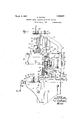
Figures 1 and 1 represent the complete machine in side elevation;
Figure 2 is a front elevation of the machine;
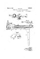
Figure 3 is a fragmentary side elevation showing the machine arranged for use as a drill press;
Figure 4 is a top plan view, and
Figure 5 is a detail view showing the detachable section of the lathe bed in end and side elevation.
Referring in detail to the drawings, .5 designates the lathe bed which is supported at one of its endsby the leg 6 of standard form and at its other end by a "box-like column 7i Upon the latter end of the' {lathe bed the headstock '8 is securedan 'el in this head stock, the spindle 9, togeth'enwi'th'the driving mechanism for the several machine units, statuses. *Upon the"-'liead"toc 1921. Serial No. 475,393.
8 there is secured a frame 10 in which the operating mechanism for the vertical drill press spindle and the vertical milling spindle is mounted," I
Upon the front side of the supportingcolumn 7 the milling lnachine knee 11 is, attached and on said knee the table and operating mechanism for the horizontal milling machine is mounted, the said table, as will be later, explained, also constituting a work support in the operation of the vertical .drill press and the vertical milling spindle.
The several mechanisms may be operated through the medium of an ordinary drive belt from an overhead countershaft, said belt transmitting power to the stepped pulley 12 on the spindle 9. As shown, the pulley 12 affords three changes of driving speed and in addition thereto,three changes ofspeed' may be secured by means of the gears 13 with which gears 14' and 14,- mounted on an eccentric shaft 15 may be thrown into mesh by actuating the handle 15 fixed to one end of the eccentric shaft. The gear 13 on the right, shown in Figure 6, is keyed upon the shaft so that it can be moved longitudinally thereon and operated by any form of lever cooperating with grooved member 13"carried by the gear 13, and is free of the pulley 1 2 but provided with ratchet teeth on its inner'face adapted to cooperate with the ratchet teeth 12gcarried by the pulley whereby the gear is engaged or disengaged with the pulley. The left hand gear 13, Figure 6, is fixed to the pulley 12. Thus atotal of six speed changes may be obtained, though it is apparent that the number of such speed changes may be further increased or decreased as the particular case might demand'or' require.
The lathe includes a tail stock 16 having its spindle axially aligned with the spindle '9', whileupon the bed of the lathe the tool carriage 1'7 with its cross slide is mounted for longitudinal movement along the bed of thellathe,through the medium of the lead screw 18, upon the guide rails 19.
Thepower'for operating the lathe is obtained from the pulley 12. Upon the spindle 91a main driving gear 20 .is fixed, said gear driving'ftheshaft 21 through-the medium of 'apair of gears 22 meshing with each other andy-moiiritediupon an ar1n23 loosely ena ed taste shes This a m l ver 24,150 position either of the gears 22 in operative relation with the gear 20 and with the gear 22 for driving the shaft 21 in reverse directions. On the other hand, the lever 24 may be moved to dispose the gears 22 in neutral position so that the shaft 21 will not be driven.
Upon the forward end of the shaft 21., a gear 25 is fixed and drives a gear 26 detachably mounted on the arm 27, said gear in turn meshing with the gear 28 on the end of the lead screw 18. The arm 27 is loosely mounted upon the bearing for the lead screw and is slotted as shown, so that transmission gears 26 of different diameters may be mounted upon said arm and engaged with the gears 25 and 28 to drive the lead screw at a desired speed. By means of the lever 24;, the gears 22 may be positioned so as to drive the tool carriage of the lathe longitudinally in either direction.
Upon the spindle 9 a drive gear 29 is fixed and meshes with a similar gear 30 fixed on an auxiliary shaft 31 mounted in a suitable bearing 32 secured upon the head stock 8. Upon this shaft a beveled gear 33 is fixed, said gear at its upper side meshing with the beveled gear 34 on the lower end of a sleeve mounted in the bearing 35. The upper end of the sleeve is provided with clutch teeth 36. The lower end of a vertieally disposed shaft 37 has the clutch member 38 keyed thereon. for longitudinal movement. This clutch member is actuated by the hand lever 39. It will be apparent that in the movement of this lever in one direction the teeth of the clutch member 38 are engaged with the clutch member 36 so that the shaft 37 will be positively driven. This shaft transmits power through the medium of the gears 40 and 41 to a horizontal shaft mounted upon the upper end of the frame 10, which in turn, transmits power through the meshing gears 42 and 4:3 to a vertically movable spindle 4-1. The gear 43 is provided with a keyway to receive a longitudinally extending key on the spindle 4 1 so that the spindle is rotated. with said gear while permitting of the free longitudinal. movement of the spindle.
In the frame 10 a shaft is mounted and upon said shaft the worm gear 46 is loosely engaged, said gear having a clutch face 47 to be engaged by a complementary clutch sleeve 48 keyed upon the shaft 45. One end of this sleeve has a ratchet 49 thereon adapted for engagement by a dog 50 mounted on the lever 51 which is loosely engaged on one end of the shaft 45. The worm gear 46 has a hub sleeve which carries a pinion meshing with the rack 52 on the sleeve 53 in which the spindle 4A is loosely engaged. A worm 54 operated by the hand wheel 55 is engaged with the upper side of the gear 46. It will thus be apparent that when the clutch member dB is in the position seen in Figure 2 of the drawings, the rack mechanism will be actuated by means of the hand wheel 55. When, however, this sleeve is shifted to engage its clutch teeth with the clutch teeth 47, the rack mechanism for moving the spindle 14 may be operated by means of the lever 51.
When the machine is to be operated as a vertical milling machine spindle 4:4: is lowered to the desired position by operating the hand wheel 55 and the clamping bolt 56 is then adjusted to tightly clamp the spindle sleeve 53 to the frame 10 so that said sleeve is rigidly held in a stationary position. The shaft or spindle is counterbalanced by means of a cable or chain indicated at 57 which is connected to a counterweight 58 guided in the frame 10, one end of the cable or chain being connected to the machine frame and the other end thereof being connected to the upper end of the sleeve 53.
When the machine is used as a horizontal milling machine, one end of a driving arbor 59 which is hollow and has its opposite ends tapered is securely clamped in the shaft extension of the spindle 9. On this arbor various sizes of milling cutters may be attached. journaled in an arm 60 fixed upon the end of an overhanging rod or shaft 61 which is longitudinally movable in the bored or tubular part 62 of the head stock 8.
When using the machine as a drill press or vertical milling machine, the arbor 59 is detached while the rod or shaft 61 with the supporting arm 60 are either removed or pushed inwardly toward the head stock and secured by means of the clamp screws 63.
The table or work bed 64 for the milling machine is mounted for longitudinal movement upon a carriage 65 which is supported upon a bed or rails on the knee 11. The power for operating this work table is transmitted from the main driving spindle 9 through the medium of the gears 29, 30, and 33, the latter gear meshing at its lower side with. a beveled gear 66 fixed upon the upper end of a shaft 67. On the lower end of the said shaft a similar beveled gear 68 is fixed and meshes with the gear 69 secured upon the end of the shaft 70. This shaft is operatively connected through suitable change speed gearing housed in the box 71 to a shaft section '72. As the particular nature of this change speed gearing whereby the work table may be moved. at varying speeds constitutes no essential. feature of the present invention. it will not be herein disclosed in detail. It will sufiice to state that this gearing may be controlled and the several speed changes readily made by the operation of a hand wheel 73. A flexible power transmitting shaft 74 con- The outer end of the arbor 59 is llll) nects the shatt section 72 to the gear 75. This flexible shaft 74 consists of several sections keyed for relative longitudinal sliding movement and having universal; joint connections to the shaft section 72 and gear 7 5 respectively to permit of theflexible shaft assuming various angles in the vertical ad j'ust'ment of the supporting knee 11. The gear Ta i-s engaged with the gear 76 secured to one end 0% a sl'ia'ft 77 on which a worm is fixed and has meshing engagement with a worm gear secured upon the table feed screw 72%. The front side oi the work table 6% is provided with a longitudinally extending sliot in which relatively adjustable trip dogs '80 are mounted. These dogs are adapted to engage a trip lever 81 at the opposite ends cit the travel of the work table to automatically reverse the direction oi travel off the work table. This automatic control means for the travel or the work table does not, however, constitute an essential part oi? the present invention and further detail reference thereto is unnecessary.
The knee 1']. may be vertically raised or lowered by means "of the crank 82 the shaft of which is provided with a 'b'cvele'd gear 83 iiiesl'iil'igwitli a similar gear 84 on the upper end of the jackscrew 81'), said screw being threaded into a sleeve fixed upon the ma 'cliine base.
' The cross or transverse movement of the work table upon the knee ll secured through the medium of "a suitable teed screw operated by the crank handle '86, said screw having threaded engagement with a part of the jc'ross slide'be'd 6 5 upon which the longitudinally movable table 64 is mounted Pret'erabl'y, the index dials 87 and 88 respectively, are provided whereby the operator can accurately position tlreknee 11 or adjust the work table transversely to properl position the work with respect to the operatingto'ol. "The vertical adjusting means tor the knee '11 and the means for c djus 'ng the work tabletran'sversely as herein disclosed are purely conventional and likewise constitiite no essential part oft "the present n'p-rovemen't.
r nt in co'nnectionwith the accompanying drawinns. it will be seen that in a very fcompact organization of thesev'eral parts, have devised a machine which may be used a's "a standard turning or engine lathe, as a horizontal milling machine, a vertical milling machine, or a drill press, and the power for operating the several instrumentalities is obtained irom a single driving shaft In addition, the bed of the lathe is provided adjacent the head stock 8 with a removable or detachable section 89, shown in Fig. 5, which is provided at opposite sides with rail portions 90 for the traveling carriage 17 1e foregoing description considered adapted to accurately align with the rails 19 of the body of the lathe bed when said section is secured in'place. in Figure 1 of the drawings, this gap section Silhas been removed from the lathe and the carriage 17 is 4' horizontal arbor 59, or, these parts may be removed and a vertical milling putter connected to the lower end of the shutter j ndle e l, or, the lathe and the drill press may be operated sin-mltaneously by attaching the drill indicated at 92 in Figure 3 to the lower end of the shaft or spindle 44 and securing the work supportingplate 93 upon the table "(i-l. As the drilling operation progresses, the drill may be lowered by operatingthe hand wheel or the lever 51.
It will thus be seen that I have produced a combination metal working machine ol maximum utility, and which will occupy tar less floor space than would be the case if separate and distinct machines are provided ea'chwith its own driving; mechanism as required for the several operations above referred to, ashas heretofore been the case. At the same time, it will be appreciated that the present invention is relatively mple in the construction and arrangement of its several parts, and, therefore, not likely to get'out of order and require frequent repair.
lVhile l have herein shown and described the preferred construction and arrangement of the several elements, it will nevertheless be Understood that the n'iachine is susceptible'of considerable modification and I aec1 .rdingly reserve the privilege of adopting all suchlegitimate changes as may be iairl y embodied withi t e Spirit and scope of the invention as claimed,
I 'I claim a a a metal Working machine or the character described, a cerre'lated drilling mechanism, a lathe mechanism and milling inecha'n'ism, including a spindle, step driven pulley mounted on said spindle, a dr ving gear mounted in said spindle for operating the drilling, lathe and milling); mechanisms, two gears mounted on said spindle, a shaft adjacent the spindle and speed varying gears keyed on the shaft and adapted to mesh with the gears on the spindle.
2. In a metal working machine of the class described, correlated drilling mechanism, lathe mechanism and milling mechanism including a spindle, a step driven pulley mounted on the spindle, a driving gear mounted on the spindle gears mounted on said spindle, speed varying gears engaging said gears, an auxiliary shaft provided with a gear engaging the driving gear of said spindle and provided with a beveled gear operating portions of said drill mechanism and milling mechanism.
3. In a metal working machine of the class described, correlated drilling mechanism, lathe mechanism and milling mechanism including a spindle, a step driven pulley mounted on said spindle, a driving gear carried by the spindle gears mounted on said spindle, speed varying gears engaging said gears carried by the spindle, an auxiliary shaft provided with a gear engaging said main driving gear, said shaft being also provided with a beveled gear, a vertically disposed sleeve having a beveled gear engaging the beveled gear of said suxiliary shaft and provided with clutch teeth, a vertically disposed shaft having a sleeve provided with clutch teeth slidingly mounted thereon, a drill shaft provided with a beveled gearing and a connecting shaft having beveled gears engaging the gear of said drill shaft and a gear on the upper end of said vertical shaft.
4. In a metal working machine of the class described, correlated drilling mechanism, lathe mechanism and milling mechanism, including a spindle, a step driven pulley mounted on said spindle, a driven gear carried by the spindle gears mounted upon said spindle, speed varying gears engaging said back gears, and an auxiliary shaft provided with a gear engaging said driving gear, a lead gear shaft on said lathe and provided with a gear and a train of gear connecting the gear of said lead shaft with the gear of said auxiliary shaft.
5. In a metal working machine of the class described, correlated drilling mechanism, lathe mechanism and milling mechanism including a spindle, a step driven pulley mounted on said spindle, a driven gear carried by the spindle gears mounted on said spindle, speed varying gears engaging said gears, an auxiliary shaft provided with a gear engaging said driving gear, a reversing gear shaft provided with a driven gear, and an arm loosely mounted upon said shaft and provided with gears engaging said driven gear and selectively engaging the gear of said auxiliary shaft, a lead screw mounted on said lathe and provided with a-gear,
and intermediate gears connecting said lead screw gear with a gear mounted upon the end of said speed varying gear shaft.
6. In ametal working machine of the class described, correlated drilling mechanism, lathe mechanism and milling mechanism including a spindle, a step driven pulley mounted on the spindle, a driving gear carried by the spindle gears mounted upon said spindle, speed varying gears engaging said gears, an auxiliary shaft having a gear mounted thereon engaging the driven gear of said spindle and having a beveled gear, means for moving the work bed of a millin machine longitudinally upon a cross sli e cooperatively connected with a beveled gear on said auxiliary shaft.
7. In a metal working machine of the class described, a lathe operating mechanism i11- cluding a spindle and a step pulley mounted on said spindle, speed changing gears on said spindle, a main drill and vertical milling machine operating mechanism and a horizontal milling machine operating mechanism, and means connected with said mechanisms and with said spindle for operating said several mechanisms simultaneously.
8. In a metal working machine of the class described, co-related drilling mechanism, lathe mechanism, and milling mechanism including a spindle, a step driven pulley mounted on said spindle for operating the drilling mechanism and the lathe, a driving gear mounted on the spindle, two gears mounted on said spindle, and speed varying gears mounted on an eccentric shaft, whereby they may be moved in and out of engagement with the gears on the spindle.
9. In a metal working machine of the character described, a co -related drilling mechanism, a lathe mechanism, a milling mechanism. including a spindle, a driven pulley mounted on said spindle, a driving gear mounted on said spindle, for operating the drilling mechanism and the lathe, two spaced gears mounted on said spindle, an eccentric shaft adjacent the spindle, and speed varying gears keyed on the shaft and adapted to mesh with the gears on the spindle, whereby the two gears may be moved in and out of engagement with the gears on the spindle.
In testimony that I claim the foregoing as my invention I have signed my name hereunder.
' llUBERT DALTON.
Priority Applications (1)
| Application Number | Priority Date | Filing Date | Title |
|---|---|---|---|
| US476393A US1620522A (en) | 1921-06-10 | 1921-06-10 | Combined lathe, drilling and milling machine |
Applications Claiming Priority (1)
| Application Number | Priority Date | Filing Date | Title |
|---|---|---|---|
| US476393A US1620522A (en) | 1921-06-10 | 1921-06-10 | Combined lathe, drilling and milling machine |
Publications (1)
| Publication Number | Publication Date |
|---|---|
| US1620522A true US1620522A (en) | 1927-03-08 |
Family
ID=23891645
Family Applications (1)
| Application Number | Title | Priority Date | Filing Date |
|---|---|---|---|
| US476393A Expired - Lifetime US1620522A (en) | 1921-06-10 | 1921-06-10 | Combined lathe, drilling and milling machine |
Country Status (1)
| Country | Link |
|---|---|
| US (1) | US1620522A (en) |
Cited By (2)
| Publication number | Priority date | Publication date | Assignee | Title |
|---|---|---|---|---|
| US2823445A (en) * | 1955-05-31 | 1958-02-18 | Richard B Lyons | Machine tool with rotatable headstock |
| US3463049A (en) * | 1967-03-27 | 1969-08-26 | John B Thomson | Machine work holding table |
-
1921
- 1921-06-10 US US476393A patent/US1620522A/en not_active Expired - Lifetime
Cited By (2)
| Publication number | Priority date | Publication date | Assignee | Title |
|---|---|---|---|---|
| US2823445A (en) * | 1955-05-31 | 1958-02-18 | Richard B Lyons | Machine tool with rotatable headstock |
| US3463049A (en) * | 1967-03-27 | 1969-08-26 | John B Thomson | Machine work holding table |
Similar Documents
| Publication | Publication Date | Title |
|---|---|---|
| US2341061A (en) | Combination machine | |
| US1620522A (en) | Combined lathe, drilling and milling machine | |
| US1751931A (en) | Stoneworking machine | |
| US2263404A (en) | Boring and milling machine | |
| US1634534A (en) | Machine tool | |
| GB329272A (en) | Improvements in or relating to combined drilling and tapping machines | |
| US2325733A (en) | Rapid traverse mechanism for lathes | |
| US694784A (en) | Automatic drilling-machine. | |
| US1977202A (en) | Boring machine | |
| US1996752A (en) | Tapping machine | |
| US1940443A (en) | Milling machine | |
| US1517431A (en) | Metal-working machine | |
| US1473356A (en) | Combination metal-working machine | |
| US1749374A (en) | Machine tool | |
| US513827A (en) | Turret-machine for boring cylinders | |
| US1700980A (en) | Intermittent drilling and tapping machine | |
| US1969791A (en) | Horizontal boring machine | |
| US548539A (en) | harden | |
| US1970810A (en) | Planer | |
| DE640637C (en) | Horizontal drilling and milling mill | |
| US1960566A (en) | Power elevator for shaping machine work tables | |
| US766747A (en) | Multiple drilling-machine. | |
| GB181311A (en) | Improvements in combined lathe, drilling and milling machines | |
| US694783A (en) | Turret drilling, milling, and tapping machine. | |
| GB261985A (en) | Improvements in or relating to metal cutting and like machine tools |