US1588198A - Sand cap for oil wells - Google Patents
Sand cap for oil wells Download PDFInfo
- Publication number
- US1588198A US1588198A US744782A US74478224A US1588198A US 1588198 A US1588198 A US 1588198A US 744782 A US744782 A US 744782A US 74478224 A US74478224 A US 74478224A US 1588198 A US1588198 A US 1588198A
- Authority
- US
- United States
- Prior art keywords
- cap
- members
- sand
- ears
- toggle
- Prior art date
- Legal status (The legal status is an assumption and is not a legal conclusion. Google has not performed a legal analysis and makes no representation as to the accuracy of the status listed.)
- Expired - Lifetime
Links
- 239000004576 sand Substances 0.000 title description 21
- 239000003129 oil well Substances 0.000 title description 2
- 210000005069 ears Anatomy 0.000 description 18
- 238000005553 drilling Methods 0.000 description 6
- 230000000295 complement effect Effects 0.000 description 5
- 210000004907 gland Anatomy 0.000 description 4
- 210000000887 face Anatomy 0.000 description 3
- 244000179328 Dieffenbachia seguine var. seguine Species 0.000 description 2
- 210000001331 nose Anatomy 0.000 description 2
- 230000002093 peripheral effect Effects 0.000 description 2
- 230000000717 retained effect Effects 0.000 description 2
- 230000001154 acute effect Effects 0.000 description 1
- 238000010276 construction Methods 0.000 description 1
- 210000003414 extremity Anatomy 0.000 description 1
- 238000012856 packing Methods 0.000 description 1
- 108010085990 projectin Proteins 0.000 description 1
- 210000001364 upper extremity Anatomy 0.000 description 1
Images
Classifications
-
- E—FIXED CONSTRUCTIONS
- E21—EARTH OR ROCK DRILLING; MINING
- E21B—EARTH OR ROCK DRILLING; OBTAINING OIL, GAS, WATER, SOLUBLE OR MELTABLE MATERIALS OR A SLURRY OF MINERALS FROM WELLS
- E21B33/00—Sealing or packing boreholes or wells
- E21B33/02—Surface sealing or packing
- E21B33/08—Wipers; Oil savers
Definitions
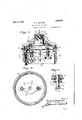
- FIG. 1 is a vertical sectional view through the upper end of the well tube, showing the device in operative position therein.
- Figure 2 is a vertical sectional view showing the device ready to be removed.
- Figure 3 is a top plan view of thestructure of Figure 1.
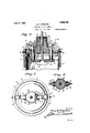
- Figure 4 is a section on the line H of Figure 2. i
- Figure 5 is a section on the line 55 of Figure 1. a
- Figure 6 is a section'on the line 6-6 of Figure 1.
- the collar 2 is interiorly provided with an inwardly directed armnlar flange 4 constituting a seat for the sand cap 5, the latter being-provided with a peripheral beveled edge 6 butat diametrically opposite points beingrecessed, as indicated at 7, with the floors or bottoms of the recesses at a more acute angle to the bottom face than the peripheral edge.
- the recesses constitute seats 'forthe ter minal armsS oftoggle members 9, the upper arms 10 of the latter having pivotal connections with thehub 11-of the cap.
- the hub 11 reduced to-provide a neck embraced by' the complemental band members 14 having terminal ears 15.
- the clamping members disposed in surrounding relation to the neck 12, the ears on the two are properly spaced to receive between them the upper arms of the toggle members and the bolts 16 which pass transversely through the ears and through the toggle members constitute combined clamping and pivotal mounting means for the toggle members.
- the toggle members are pivotally jointed intermediately, as at 17, the pivot pins constituting the connections between the upper' and lower arms, and when the lower arms rest in the bottoms of the recesses 7,. the noses of said arms engage under the extremities of the set-screws 18 radially threaded through the collar 2 and projectin from ,the interior wall of the latter a slig 1t distance above the seating flange 4.
- the pivot points 17 are slightly below the in clined planes passing through the centers of the bolts 16 and the lines of contact between the arms and the set-screws 18 and thus the cap is locked in position on the collar and thia1 well tube thereby closed at the upper en
- the cap 5 and its hub 11 are axially bored, as indicated at 19, to provide for.
- the free movement of the cable 20 carrying the tool 21 and the hub 11 abovethe neck is exteriorly threaded, as indicated at 22, for the reception of a cap 23 bored to permit the passage of thecable but snugly fitting the latter and retaining in place the packing- 24which will preclude leakage from the well around the cable.
- a trip plate 25 provided with a clearanceeye or hole 26 for the'passage of the cable 20. Adjacent-opposite ends, the trip plate is provided with the upstanding studs 27 reduced at their lower ends, as indicated at 28, and assing through holes in the trip plate an secured to the latter by riveting or peening over, as indicated at 29.
- the studs or posts 27 constitute the trip elements for the toggle members, and to this end pass slidingly through eyes 30 formed in the sand cap and adjacent their upper extremities receive transverse pins 31 bearing on the top of the cap to limit downward remain seated in the recesses 7 and the cap is retained in place.
- the studs or posts 27 are raised with the result that the toggle members are broken at the center, resultin in the withdrawal of the noses of the lower arms 8 from the set-screws, thereby releasing the cap, and if the tool 21 be the means for 1mparting the upward movement to the trip plate, as intended inpractice, the cap and all its component parts, will be released from the collar and withdrawn from place by the tool.
- the posts or studs 27 are surrounded by compress on springs 36 bearing at their lower ends on the trip plate and at their upper ends on the glands 37 seated in counterbores 38 in the sand cap and compressing the packlng 39 which surrounds the studs or posts and prevents leakage around them;
- the glands are retained in position by the cap-screws 40 threadingly engaging the cap 5.
- a terminal fitting for a well tubing constituting a seat for a sand cap, a sand cap having toggle members for engaging said fitting and locking the cap on the seat, and a tripping member yieldingly impelled away from said togglemembers and adapted for actuation by a drilling tool, the tripping member being provided with elements engaging the toggle members at the toggle joints.
- a terminal fitting for a well tubing constituting a seat for a sand cap, a sand cap having a hub portion, toggle members having one arm each pivotally connected with said hub portion and adapted for terminal engagement of the other arms with the fitting to lock the cap on the seat, and a trip consisting of a plate disposed in obstructing relation to a drilling tool and provided with studs for impact engagement with the toggle members at. the toggle joints.
- a sand cap having a hub provided with areduced neck portion, complementary clamping members seated in said neckportion and provided with terminal ears, bolts spanning the ears of said clamping members, toggle members having one arm disposed between adjacent ears and pivotally engaging said bolt and the other arms adapted for terminal engagement with the fitting to retain the cap on the seat, and tool operating tripping means operatively engaging with the toggle members at the toggle joints.
- a sand cap having-a hub provided with a reduced neck portion, complementary clamping members seated in said neck portion and provided with terminal ears, bolts spanning the ears of said clamping members, toggle members having one arm disposed between adjacent ears and pivotally engaging said bolt andthe other arms adapted for terminal engagement with the fitting to retain the cap on the seat, and a trip plate disposed in obstructing relation toa drilling tool and provided with studs slidably fitted in the cap and terminally engaged with the toggle members at the toggle joints.
- sand cap a sand cap having a hub provided 7 with a reduced neck portion, complementary clamping members seated in said neck portion and provided with terminal ears, bolts spanning the ears of said clamping members, toggle members having one arm disposed between adjacent ears and pivotally engaging said bolt and the other arms adapted for terminal engagement with the fitting to retain the cap on the seat, a trip plate provided with a central opening for the passage of the drilling tool cable, studs carried by said plate and slidably engaging eyes formed in the sand cap, the upper terminals of said studs engaging the toggle members at the toggle joints, and sprlngs disposed in surrounding relation to the studs and bearing on the plate to normally force the latter in a direction away from the sand cap.
- a sand cap having a hub provided with a reduced neck portion, complementary clamping members seated in said neck portion and provided with terminal ears, bolts spanning the ears of said clamping members, toggle members having one arm disposedbetween adjacent ears and pivotally engaging said bolt and the other arms adapted for terminal engagement with the fitting to retain the ca on the seat, a trip plate provided with a c earance opening for a drilling tool cable, studs mounted in the plate and slidably engaging the openings formed in the cap, said openings being counterbored, glands secured in the counterbores, and a packing disposed in surrounding relacombination with a terminalfitting tion to the studs and compressed by the glands, the upper terminals of said studs being engaged withthe toggle members at the toggle joints.
- a sand cap having a hub provided with a reduced neck portion, complementary clamping members seated in said neckportion and provided with terminal ears, bolts spanning the ears of said clamping members, toggle members having one arm disposed between adjacent ears and pivotally engaging said bolt and the other arms adapted for terminal engagement with the fitting to retain the cap on the seat, a trip plate rovided with a'central opening to provi e a clearance space for a drilling.
Landscapes
- Life Sciences & Earth Sciences (AREA)
- Engineering & Computer Science (AREA)
- Geology (AREA)
- Mining & Mineral Resources (AREA)
- Physics & Mathematics (AREA)
- Environmental & Geological Engineering (AREA)
- Fluid Mechanics (AREA)
- General Life Sciences & Earth Sciences (AREA)
- Geochemistry & Mineralogy (AREA)
- Earth Drilling (AREA)
Description
June 8,1926. 1,588,198.
G. A. SEGUINE SAND CAP FOR OIL WELLS Filed 001. 20, 1924 2 Sheets- Sheet 1 azy. 1.1 v
I al ke: nu,
June 8', 1926. 1,588,198
1 G. A. SEGUINE SAND GAP FOR 011. WELLS Filed Oct. 20, 1924 2 Sheets-Sheet 2 I 19 4 v 1s 11 9 a1 6 a! s a I 7 m M I 4 1 4 5 a? as i Y K 36 as! as 6 as v Guy A. Segutne V 2' v v ready:
Patented June 8, 1926.
v UNITED STATES v 1,588,198 PATENT OFFICE.
GUY A. SEGUINE, OF BLACKWELL, OKLAHOMA, ASSIGNOR OF ONE-SIXTEENTH TO FBEDERICK A. 051, OF FREDONIA,
KANSAS, ONE-FIFTH TO 0. J. BROWN, AND
ONE-FIFTH TOW. E. LUCAS, BOTH OF TONKAWA, OKLAHOMA.
SAND CAP FOB OIL WELLS.
Application filed.0ctober 20, 1924. Serial No. 744,782.
With these objects in view, the invention.
consists in a construction and combination of parts of which a preferred embodiment is illustrated in the accompanying drawings, wherein:
- Figure 1 is a vertical sectional view through the upper end of the well tube, showing the device in operative position therein.
Figure 2 is a vertical sectional view showing the device ready to be removed.
Figure 3 is a top plan view of thestructure of Figure 1.
Figure 4 is a section on the line H of Figure 2. i
Figure 5 is a section on the line 55 of Figure 1. a
- Figure 6 is a section'on the line 6-6 of Figure 1.
In carrying out the invention, there is attached to the top of the well tubing 1 the collar 2 interiorly threaded, as at 3, for engagement with the exterior threads on the upper end of the'top length of the well tube.
The collar 2 is interiorly provided with an inwardly directed armnlar flange 4 constituting a seat for the sand cap 5, the latter being-provided with a peripheral beveled edge 6 butat diametrically opposite points beingrecessed, as indicated at 7, with the floors or bottoms of the recesses at a more acute angle to the bottom face than the peripheral edge.
' The recesses constitute seats 'forthe ter minal armsS oftoggle members 9, the upper arms 10 of the latter having pivotal connections with thehub 11-of the cap. In order to providefor the pivotal connections of the tp gglezrnembers and to also provide for the disassembling ofthe parts the hub 11 reduced to-provide a neck embraced by' the complemental band members 14 having terminal ears 15. lVith the clamping members disposed in surrounding relation to the neck 12, the ears on the two are properly spaced to receive between them the upper arms of the toggle members and the bolts 16 which pass transversely through the ears and through the toggle members constitute combined clamping and pivotal mounting means for the toggle members.
' The toggle members are pivotally jointed intermediately, as at 17, the pivot pins constituting the connections between the upper' and lower arms, and when the lower arms rest in the bottoms of the recesses 7,. the noses of said arms engage under the extremities of the set-screws 18 radially threaded through the collar 2 and projectin from ,the interior wall of the latter a slig 1t distance above the seating flange 4. With the lower arms engaged under the set-screws, the pivot points 17 are slightly below the in clined planes passing through the centers of the bolts 16 and the lines of contact between the arms and the set-screws 18 and thus the cap is locked in position on the collar and thia1 well tube thereby closed at the upper en The cap 5 and its hub 11 are axially bored, as indicated at 19, to provide for. the free movement of the cable 20 carrying the tool 21 and the hub 11 abovethe neck is exteriorly threaded, as indicated at 22, for the reception of a cap 23 bored to permit the passage of thecable but snugly fitting the latter and retaining in place the packing- 24which will preclude leakage from the well around the cable.
In order that the cap may be released from engagement with its seat upon the elevation of the tool to the top of the well, there is provided in connection with the cap a trip plate 25 provided with a clearanceeye or hole 26 for the'passage of the cable 20. Adjacent-opposite ends, the trip plate is provided with the upstanding studs 27 reduced at their lower ends, as indicated at 28, and assing through holes in the trip plate an secured to the latter by riveting or peening over, as indicated at 29.
The studs or posts 27 constitute the trip elements for the toggle members, and to this end pass slidingly through eyes 30 formed in the sand cap and adjacent their upper extremities receive transverse pins 31 bearing on the top of the cap to limit downward remain seated in the recesses 7 and the cap is retained in place. Upon imparting an upward movement to the trip plate, how-, ever, the studs or posts 27 are raised with the result that the toggle members are broken at the center, resultin in the withdrawal of the noses of the lower arms 8 from the set-screws, thereby releasing the cap, and if the tool 21 be the means for 1mparting the upward movement to the trip plate, as intended inpractice, the cap and all its component parts, will be released from the collar and withdrawn from place by the tool.
In order toimpose against the too free movement of the trip plate, the posts or studs 27 are surrounded by compress on springs 36 bearing at their lower ends on the trip plate and at their upper ends on the glands 37 seated in counterbores 38 in the sand cap and compressing the packlng 39 which surrounds the studs or posts and prevents leakage around them; The glands are retained in position by the cap-screws 40 threadingly engaging the cap 5.
The invention having been described, what is claimed as new and useful is: t
1. In combination with a terminal fitting for a well tubing constituting a seat for a sand cap, a sand cap having toggle members for engaging said fitting and locking the cap on the seat, and a tripping member yieldingly impelled away from said togglemembers and adapted for actuation by a drilling tool, the tripping member being provided with elements engaging the toggle members at the toggle joints.
2. In combination with a terminal fitting for a well tubing constituting a seat for a sand cap, a sand cap having a hub portion, toggle members having one arm each pivotally connected with said hub portion and adapted for terminal engagement of the other arms with the fitting to lock the cap on the seat, and a trip consisting of a plate disposed in obstructing relation to a drilling tool and provided with studs for impact engagement with the toggle members at. the toggle joints.
3. In combination with a terminal fitting for a well tubing'constituting a seat-for a sand cap, a sand cap having a hub provided with areduced neck portion, complementary clamping members seated in said neckportion and provided with terminal ears, bolts spanning the ears of said clamping members, toggle members having one arm disposed between adjacent ears and pivotally engaging said bolt and the other arms adapted for terminal engagement with the fitting to retain the cap on the seat, and tool operating tripping means operatively engaging with the toggle members at the toggle joints.
4. In combination with a terminal fitting for awell tubing constituting a seat for a sand cap, a sand cap having-a hub provided with a reduced neck portion, complementary clamping members seated in said neck portion and provided with terminal ears, bolts spanning the ears of said clamping members, toggle members having one arm disposed between adjacent ears and pivotally engaging said bolt andthe other arms adapted for terminal engagement with the fitting to retain the cap on the seat, and a trip plate disposed in obstructing relation toa drilling tool and provided with studs slidably fitted in the cap and terminally engaged with the toggle members at the toggle joints.
5. In combination with a terminal fitting for a well tubing constituting a seat for a.
sand cap, a sand cap having a hub provided 7 with a reduced neck portion, complementary clamping members seated in said neck portion and provided with terminal ears, bolts spanning the ears of said clamping members, toggle members having one arm disposed between adjacent ears and pivotally engaging said bolt and the other arms adapted for terminal engagement with the fitting to retain the cap on the seat, a trip plate provided with a central opening for the passage of the drilling tool cable, studs carried by said plate and slidably engaging eyes formed in the sand cap, the upper terminals of said studs engaging the toggle members at the toggle joints, and sprlngs disposed in surrounding relation to the studs and bearing on the plate to normally force the latter in a direction away from the sand cap. j i
6. In fora well tubing constituting a seat for a sand cap, a sand cap having a hub provided with a reduced neck portion, complementary clamping members seated in said neck portion and provided with terminal ears, bolts spanning the ears of said clamping members, toggle members having one arm disposedbetween adjacent ears and pivotally engaging said bolt and the other arms adapted for terminal engagement with the fitting to retain the ca on the seat, a trip plate provided with a c earance opening for a drilling tool cable, studs mounted in the plate and slidably engaging the openings formed in the cap, said openings being counterbored, glands secured in the counterbores, and a packing disposed in surrounding relacombination with a terminalfitting tion to the studs and compressed by the glands, the upper terminals of said studs being engaged withthe toggle members at the toggle joints.
7 In combination with a terminal fitting for a well tubing constituting a seat for a sand cap, a sand cap having a hub provided with a reduced neck portion, complementary clamping members seated in said neckportion and provided with terminal ears, bolts spanning the ears of said clamping members, toggle members having one arm disposed between adjacent ears and pivotally engaging said bolt and the other arms adapted for terminal engagement with the fitting to retain the cap on the seat, a trip plate rovided with a'central opening to provi e a clearance space for a drilling. tool cable per 'ends having impact faces and related cam faces, and one arm of each of the tog-' gle members having an impact face engaging the impact face of the stud and the other arms having rounded edges engaging the cam faces ofthe studs, and springs bearing upon the trip plate and normally impelling it in a direction away from the sand cap. a In testimony whereof he aflixeshis signa ture. GUY A. SEGUIN E.
Priority Applications (1)
| Application Number | Priority Date | Filing Date | Title |
|---|---|---|---|
| US744782A US1588198A (en) | 1924-10-20 | 1924-10-20 | Sand cap for oil wells |
Applications Claiming Priority (1)
| Application Number | Priority Date | Filing Date | Title |
|---|---|---|---|
| US744782A US1588198A (en) | 1924-10-20 | 1924-10-20 | Sand cap for oil wells |
Publications (1)
| Publication Number | Publication Date |
|---|---|
| US1588198A true US1588198A (en) | 1926-06-08 |
Family
ID=24993972
Family Applications (1)
| Application Number | Title | Priority Date | Filing Date |
|---|---|---|---|
| US744782A Expired - Lifetime US1588198A (en) | 1924-10-20 | 1924-10-20 | Sand cap for oil wells |
Country Status (1)
| Country | Link |
|---|---|
| US (1) | US1588198A (en) |
Cited By (2)
| Publication number | Priority date | Publication date | Assignee | Title |
|---|---|---|---|---|
| US20040159438A1 (en) * | 2003-01-27 | 2004-08-19 | Reimert Larry E. | Control pod latchdown mechanism |
| US20050070150A1 (en) * | 2003-09-23 | 2005-03-31 | Williams Alfred Moore | Assembly for connecting a jumper to a subsea structure |
-
1924
- 1924-10-20 US US744782A patent/US1588198A/en not_active Expired - Lifetime
Cited By (4)
| Publication number | Priority date | Publication date | Assignee | Title |
|---|---|---|---|---|
| US20040159438A1 (en) * | 2003-01-27 | 2004-08-19 | Reimert Larry E. | Control pod latchdown mechanism |
| US6907932B2 (en) | 2003-01-27 | 2005-06-21 | Drill-Quip, Inc. | Control pod latchdown mechanism |
| US20050070150A1 (en) * | 2003-09-23 | 2005-03-31 | Williams Alfred Moore | Assembly for connecting a jumper to a subsea structure |
| US7318479B2 (en) * | 2003-09-23 | 2008-01-15 | Dril-Quip, Inc. | Assembly for connecting a jumper to a subsea structure |
Similar Documents
| Publication | Publication Date | Title |
|---|---|---|
| US1588198A (en) | Sand cap for oil wells | |
| US2278050A (en) | Well head closure | |
| DE202011101484U1 (en) | Bucket tooth for construction machine | |
| US1847087A (en) | Spider and slip construction | |
| US2092793A (en) | Relief valve | |
| US1482944A (en) | Releasable wire-rope socket | |
| US1857321A (en) | Fluid control device | |
| US502750A (en) | Valve for oil-well pumps | |
| CN103821805B (en) | A kind of guideway vehicle and press-in unlocking type equipment case lid secondary protection device thereof | |
| US2919900A (en) | Bumper safety joint | |
| US1822140A (en) | Plug for oil wells and apparatus for seating the same | |
| US1652542A (en) | Lock joint for standing valves and the like | |
| US2937659A (en) | Ball valve cage | |
| US1599144A (en) | Well elevator | |
| US2330266A (en) | Cementing plug | |
| US1398216A (en) | Safety device for mine-elevators | |
| US1566419A (en) | Oil and gas saving and life-saving collar for oil and gas well drilling outfits | |
| US1781199A (en) | Fitting for electrical conduits | |
| US1695332A (en) | Oil saver for oil wells and packing screws therefor | |
| US2851242A (en) | Gate valve | |
| EP3126283A2 (en) | Filling adapter (aeration line) | |
| US2234438A (en) | Tool removing device | |
| US1895636A (en) | Adjustable choke nipple | |
| DE831276C (en) | Device for connecting several flush-mounted boxes | |
| US836065A (en) | Pipe-pulling device. |