US1576830A - Engine - Google Patents
Engine Download PDFInfo
- Publication number
- US1576830A US1576830A US677101A US67710123A US1576830A US 1576830 A US1576830 A US 1576830A US 677101 A US677101 A US 677101A US 67710123 A US67710123 A US 67710123A US 1576830 A US1576830 A US 1576830A
- Authority
- US
- United States
- Prior art keywords
- cross
- engine
- head
- cylinder
- crank case
- Prior art date
- Legal status (The legal status is an assumption and is not a legal conclusion. Google has not performed a legal analysis and makes no representation as to the accuracy of the status listed.)
- Expired - Lifetime
Links
Images

Classifications
-
- F—MECHANICAL ENGINEERING; LIGHTING; HEATING; WEAPONS; BLASTING
- F01—MACHINES OR ENGINES IN GENERAL; ENGINE PLANTS IN GENERAL; STEAM ENGINES
- F01L—CYCLICALLY OPERATING VALVES FOR MACHINES OR ENGINES
- F01L29/00—Reversing-gear
- F01L29/04—Reversing-gear by links or guide rods
Definitions
- An ob ect of our invention is to provide described a device by means of which the stroke of the slide valves associated with a plurality of cylinders may be simultaneously regulat-' ed so as to admit a predetermined amount of steam to the cylinders.
- a further object of our invention is to provide a device of the type described,
- a further object of our invention is to provide an engine having a novel form of cross-head guide so arranged as to consume a minimum amount of energy in friction.
- a further object of our invention is to provide an engine of the V-cy1inder type arrangement, in which the valve stroke control mechanism is enclosed in the crank case, thereby insuring efficient lubrication, and also the protection of the working parts.
- Figure 5 1s a sect on along the line 5-65 of Figure 4,
- Figure 6 is a side view of one of the crosshead guides, I
- Figure 7 is a diagrammatic view showing the ports in the steam chest.
- Figure 8 is a diagran'imatic view showing a slide valve.
- a support 1 having an opening 2 therein, arranged to receive the bottom 3 of the crank case.
- the crank case proper is made preferably of a casting, and is provided with portions 4 which rest upon the support 1 (see Figures 2 and 3). Adjacent to the portions Land integral therewith are portions 5, which are inclined and which form the parts to which the cylinders are secured. An integral cover or top portion 6 connects the portions 5, as will be seen from the drawings.
- a pair of opposed cylinders angularly dis posed with respect to one another, as in the V type, but offset to permit connection to a common crank shaft. 1
- the block 'lfi'sl ideslin a guide member shown in Figure 6.j
- This cross-head guide consists of a body portion 20 having a head or end plate 21, and it is provided with arms 22 having guide strips 23 on which the block slides, as shown in Figure 5.
- crank shaft 32 On the crank shaft 32 are pair of eccentrics 33 which are connected by rods 34- with heads 35, disposed in the respective slots-3U otthe levers 29. These heads 35 are connected by links 3-6 with a lever 37, which is mounted on a shaft 38, to which a handle 39 is connected.
- a crank case a crank case, a cylinder disposed externally of said crank case, a removable cross head guide having a portion extending into said crank case, a piston in said cylinder, a piston rod, a cross head secured to said piston rod and arranged to reciprocate on said cross head guide within said crank case, and means for securingsaid cylinder and said removable cross head guide to said crank case, said'sccuring means also serving a spacing means for spacing said cylinder from said. cross head guide.
- a crank case having: an opening in the wall thereof, a closure for said opening, said closure extending into the crank case and constituting a cross head guide.
- a cross head arranged to reciprocate on said cross head guide, a cylinder, a piston within the cylinder, a piston rod connecting said piston with said cross head, spacing sleeves disposed between said cylinder and said closure, andbolts arranged to pass through said spacing sleeves for securing said cylinder at a spaced distance fromsaidclosure, andior locking said closure to the crank case. wall.
Landscapes
- Engineering & Computer Science (AREA)
- Mechanical Engineering (AREA)
- General Engineering & Computer Science (AREA)
- Cylinder Crankcases Of Internal Combustion Engines (AREA)
Description
March 16 1926.
w, y. JORDAN ET AL ENGINE Filed Nov. 26; 1923 2 Sheets-Sheet 1 BYLK mfiiam ZTTORNEY-S' Mud; 16,1926.
. 1,576,830 w. v. JORDAN Er m.
ENGINE Filed Nov. 26. 1923 2 Sheets-Sheet 2 l j "I vmmn BY I Patented Mar. 16, 19260 UNITED STATES PATENT OFFICE.
WILLIAM VIRGIL JORDAN AND THOMAS MARSHALL SWANK, OF LOUISVILLE,
. KENTUCKY.
ENGINE.
Application filed November 26, 1923.
engines, more particularly to a novel valve controlling mechanism for steam engines,
and it consists in the combinations,construetions, and arrangements herein and claimed.
An ob ect of our invention is to provide described a device by means of which the stroke of the slide valves associated with a plurality of cylinders may be simultaneously regulat-' ed so as to admit a predetermined amount of steam to the cylinders.
A further object of our invention is to provide a device of the type described,
which may be operated even while the en glue is running, thereby obviating the notes sity of stopping the engine to adjust the travel of the valves.
A further object of our invention is to provide an engine having a novel form of cross-head guide so arranged as to consume a minimum amount of energy in friction. A further object of our invention is to provide an engine of the V-cy1inder type arrangement, in which the valve stroke control mechanism is enclosed in the crank case, thereby insuring efficient lubrication, and also the protection of the working parts. Other objects and advantages will appear in the following specification, and the novel features of the invention will be particularly pointed out in the appended claims.
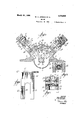
Our invention is illustrated int-he ac Figure l is an enlarged section along the,
line 4-4 of Figure 2,
Figure 5 1s a sect on along the line 5-65 of Figure 4,
Serial No. 677,101.
Figure 6 is a side view of one of the crosshead guides, I
Figure 7 is a diagrammatic view showing the ports in the steam chest, and
Figure 8 is a diagran'imatic view showing a slide valve.
In carrying out our invention, we provide a support 1 having an opening 2 therein, arranged to receive the bottom 3 of the crank case. The crank case proper is made preferably of a casting, and is provided with portions 4 which rest upon the support 1 (see Figures 2 and 3). Adjacent to the portions Land integral therewith are portions 5, which are inclined and which form the parts to which the cylinders are secured. An integral cover or top portion 6 connects the portions 5, as will be seen from the drawings. In the drawings, we have shown a pair of opposed cylinders angularly dis posed with respect to one another, as in the V type, but offset to permit connection to a common crank shaft. 1
In Figure 2, it willbe observed that the cylinders 7 and 8 are secured to the portions 5 by means of rods 9 which pass through extensions or flanges 10 of the cyl inders. Each cylinder is closed at its outer end by heads 11, which are screwed in place. The opposite end of'the cylinder has a head 12, and a stufiing box 13 connected thereto. The pistons 14 are connected by piston rods 15 with a cross-head L6. The construction of this cross-head is best shown in Figure 5. It will be seen that it comprises a block 16 having a wrist pin 17 extending therethrough. This wrist pin is mounted in roll- The piston rod is forked er bearings 18. I at its-end to 'straddlethe pitn ian 19, and the forked ends of thepiston rods are pinned to the wrist-pin, as shown in Figure 4. The block 'lfi'slideslin a guide member shown in Figure 6.j This cross-head guide consists of a body portion 20 having a head or end plate 21, and it is provided with arms 22 having guide strips 23 on which the block slides, as shown in Figure 5. The arm 22, as
will be seen from Figure 2, passes through an opening in the portion 5 of'the crank case, and the plate 21 is held in position by means of sleeves 24 which surround the rods 9, thus holding the cross-head guides rigidl in position.
It will be understood tha the ylinder on the opposite side oi the center line through the crank shaft at 31. On the crank shaft 32 are pair of eccentrics 33 which are connected by rods 34- with heads 35, disposed in the respective slots-3U otthe levers 29. These heads 35 are connected by links 3-6 with a lever 37, which is mounted on a shaft 38, to which a handle 39 is connected.
From the foregoing;description of the various parts of the device, the". operation thereofinay be readily understood Steam is admitted to the steam chest and passes into the cylinders 7, driving the pistons l ft in the usual manner. The movement is transmitted to the cross-head 16' which slides in the cross-head guides 22', and through the pitman 19 to the crankshaft The latter is provided with ball bearingsat its connection with the. pitmair 19, and also within thec 'ank case; The, movement of the crank shaft 32 causes a reciprocatory movement ofthe eccentrics 33, and consequently an oscillatingmovement of the levels 29. This in turn, imparts, a reci'procatory move=- ment to the valve rods 26, and causes the movement of the valves 25 to control" the admissioi'r and the exhaust of the steam.
In Figure 3, when the, rods 34 a're'iii the position indicated in full lines, they will 25, this passage would connect the porty/ and the cxhaustportc, when the valve; is in the position shown in dotted lines; This would ccur when'the arms 34 are thrown farthest away from the 'dottedli'ne position,shown The: port 2)" 'wou'ldhe taking in the full amountof steami "If now the handle 39' ismoved so as to hring the arms in Figure 8.
In Fi ure 3 we haveshowna steam Si in Figure 3 to the dotted line position, then the valve would have been n'ioved to its full lineposition, shown in Figure T, and instead of opening the ports and p tully it would only open them partially, thus letting less steam in. Now there are certain conditions in which it is very advantageous toregulate the admission of steam to the cylinder, other than by the throttle. Thus, where the load 'issuch that it could be operated by a reduced amount of steam, the valves may beadjusted so that this will be effected. Since the exhaust is always fully open at the end of the throw of the valve, the result is that there is a decrease oi back pressure, and the engine'is run more economically.
The provision of rcnu able cross-head guides adds to the sin'iplicity and economical manufacture of the engine, and it also provides anefficient means for lubrication, since it will be observed that'the cross-head guides extend into the crankcase, where they can be virtually bathed in oil, as for instance, by a splash system.
\Ve claim:
1. In an engine, a crank case, a cylinder disposed externally of said crank case, a removable cross head guide having a portion extending into said crank case, a piston in said cylinder, a piston rod, a cross head secured to said piston rod and arranged to reciprocate on said cross head guide within said crank case, and means for securingsaid cylinder and said removable cross head guide to said crank case, said'sccuring means also serving a spacing means for spacing said cylinder from said. cross head guide.
2. In an engine, a crank case having: an opening in the wall thereof, a closure for said opening, said closure extending into the crank case and constituting a cross head guide. a cross head arranged to reciprocate on said cross head guide, a cylinder, a piston within the cylinder, a piston rod connecting said piston with said cross head, spacing sleeves disposed between said cylinder and said closure, andbolts arranged to pass through said spacing sleeves for securing said cylinder at a spaced distance fromsaidclosure, andior locking said closure to the crank case. wall. a
WILIZI'A \ti' VIE-GIL JOB-BAIT. THOMAS li [ARSHALLL
Priority Applications (1)
| Application Number | Priority Date | Filing Date | Title |
|---|---|---|---|
| US677101A US1576830A (en) | 1923-11-26 | 1923-11-26 | Engine |
Applications Claiming Priority (1)
| Application Number | Priority Date | Filing Date | Title |
|---|---|---|---|
| US677101A US1576830A (en) | 1923-11-26 | 1923-11-26 | Engine |
Publications (1)
| Publication Number | Publication Date |
|---|---|
| US1576830A true US1576830A (en) | 1926-03-16 |
Family
ID=24717330
Family Applications (1)
| Application Number | Title | Priority Date | Filing Date |
|---|---|---|---|
| US677101A Expired - Lifetime US1576830A (en) | 1923-11-26 | 1923-11-26 | Engine |
Country Status (1)
| Country | Link |
|---|---|
| US (1) | US1576830A (en) |
Cited By (2)
| Publication number | Priority date | Publication date | Assignee | Title |
|---|---|---|---|---|
| US2511905A (en) * | 1950-06-20 | Two-cycle multiple cylinder diesel | ||
| US2837062A (en) * | 1957-03-28 | 1958-06-03 | Thorpe Joseph | Hydraulic power unit |
-
1923
- 1923-11-26 US US677101A patent/US1576830A/en not_active Expired - Lifetime
Cited By (2)
| Publication number | Priority date | Publication date | Assignee | Title |
|---|---|---|---|---|
| US2511905A (en) * | 1950-06-20 | Two-cycle multiple cylinder diesel | ||
| US2837062A (en) * | 1957-03-28 | 1958-06-03 | Thorpe Joseph | Hydraulic power unit |
Similar Documents
| Publication | Publication Date | Title |
|---|---|---|
| US1736639A (en) | Driving mechanism for internal-combustion engines | |
| US1782975A (en) | High-pressure reciprocating compressor | |
| US2434584A (en) | Multiple cylinder opposed piston and pumps | |
| US2295962A (en) | Multiple cylinder steam engine and valve gear therefor | |
| US1660487A (en) | Internal-combustion engine | |
| US1442995A (en) | Internal-combustion engine | |
| US779727A (en) | Counterweight attachment for gas-engines. | |
| US1789376A (en) | Air compressor | |
| US745814A (en) | Reversible driving-gear. | |
| US499584A (en) | player | |
| US1088609A (en) | Engine-valve. | |
| US380375A (en) | willans | |
| US455555A (en) | Valve-motion for duplex engines | |
| US1306198A (en) | stanley | |
| US1151434A (en) | Two-stroke-cycle internal-combustion engine. | |
| US922036A (en) | Engine valve-gear. | |
| US1568615A (en) | Overhead cam shaft and valve gear | |
| US871471A (en) | Lead-controlling mechanism for steam-engines. | |
| US1518033A (en) | Two-stroke cycle combustion engine | |
| US919207A (en) | Valve-gear for steam-engines. | |
| US1917429A (en) | Compressor drive apparatus | |
| US1912285A (en) | Internal combustion engine | |
| US1222266A (en) | Steam-engine valve and valve-gear. | |
| US1127924A (en) | Valve-operating gear of internal-combustion engines. | |
| US1706394A (en) | Liquid-operated brake for motor vehicles |