US1574486A - Radiator cap and overflow pipe - Google Patents
Radiator cap and overflow pipe Download PDFInfo
- Publication number
- US1574486A US1574486A US729819A US72981924A US1574486A US 1574486 A US1574486 A US 1574486A US 729819 A US729819 A US 729819A US 72981924 A US72981924 A US 72981924A US 1574486 A US1574486 A US 1574486A
- Authority
- US
- United States
- Prior art keywords
- cap
- radiator
- overflow pipe
- ring
- pipe
- Prior art date
- Legal status (The legal status is an assumption and is not a legal conclusion. Google has not performed a legal analysis and makes no representation as to the accuracy of the status listed.)
- Expired - Lifetime
Links
Images
Classifications
-
- F—MECHANICAL ENGINEERING; LIGHTING; HEATING; WEAPONS; BLASTING
- F01—MACHINES OR ENGINES IN GENERAL; ENGINE PLANTS IN GENERAL; STEAM ENGINES
- F01P—COOLING OF MACHINES OR ENGINES IN GENERAL; COOLING OF INTERNAL-COMBUSTION ENGINES
- F01P11/00—Component parts, details, or accessories not provided for in, or of interest apart from, groups F01P1/00 - F01P9/00
- F01P11/02—Liquid-coolant filling, overflow, venting, or draining devices
- F01P11/0285—Venting devices
-
- F—MECHANICAL ENGINEERING; LIGHTING; HEATING; WEAPONS; BLASTING
- F01—MACHINES OR ENGINES IN GENERAL; ENGINE PLANTS IN GENERAL; STEAM ENGINES
- F01P—COOLING OF MACHINES OR ENGINES IN GENERAL; COOLING OF INTERNAL-COMBUSTION ENGINES
- F01P2025/00—Measuring
- F01P2025/70—Level
-
- Y—GENERAL TAGGING OF NEW TECHNOLOGICAL DEVELOPMENTS; GENERAL TAGGING OF CROSS-SECTIONAL TECHNOLOGIES SPANNING OVER SEVERAL SECTIONS OF THE IPC; TECHNICAL SUBJECTS COVERED BY FORMER USPC CROSS-REFERENCE ART COLLECTIONS [XRACs] AND DIGESTS
- Y10—TECHNICAL SUBJECTS COVERED BY FORMER USPC
- Y10S—TECHNICAL SUBJECTS COVERED BY FORMER USPC CROSS-REFERENCE ART COLLECTIONS [XRACs] AND DIGESTS
- Y10S220/00—Receptacles
- Y10S220/32—Radiator cap
Definitions
- This invention relates to improvements in radiator caps and overflow pipes for motor vehicles.
- An object of the present invention is to so combine a closure cap and owriiow pipe in order that this pipe will not work loose or become detached when in use.
- difficulties have often been experienced by having the overflow in some types ot i'notor vehicles working loose or becom ing completely detached from the radiator.
- my l1i'lp1() ⁇ *l'l'l611t consists in securing a metallic ring between the inner surface of the cap and the radiator filling tube, which ring serves as a packing ring, and, to this ring is permanently secured the overflow pipe which consists of a piece of tubing of suitable size, as generally employed tor this purpose.
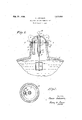
- Fig. l is a view showing my in'iprovement in place on the upper end of the filling tube of the radiator, also illustrating the float construction
- v Fig. 2 is a detail horizontal sectional View on the line 2-2 of Fig. 1.
- 1 designates the upper portion of the radiator
- 2 the filling tube for introducing the cooling water into the radiator
- 3 the closure cap for the tube having the usual integral wing portions t for threading the cap onto the tube.
- Formed on the lower inner surface of the cap are the internal threads 5 which mesh with the external threads on the upper end of the filling tube.
- 6 is a metallic ring which is loosely placed in the annular groove 7. It serves as a packing ring between the upper end of the filling pipe 2 and the cap.
- 8 designates the upper portion of the overflow pipe. This pipe is secured to the ring 6 by inserting the same through an opening 9 which is "formed in the enlarged or extension portion 11 ot the metallic ring (3.
- the overflow tube 8 is permanently secured in this opening by soldering indicated at 11, or otherwise so that when the cap 3 is threaded onto or away from the filling tube 2 it will serve to firmly clamp the ring in place, and at the same time retain the pipe 8 against displacement.
- the device is used as follows: When the cap 8 slipped over the pipe 8 and soldered thereto, then when the cap is threaded onto the tube 2 the ring 6 and overflow pipe 8 will be firmly secured in place.
- a, depending tubular member 11 which is secured by means of solder. indi cated at 12. The lower end of this member is closed with the washer 13 and packing 1d.
- the upper end 01" the cap is formed with an opening 15.
- 16 designates a metallic fioat to which is attached the rod 17.
- the upper end of the rod is provided with an indicating ball 18, whereby the level of the water in the radiator may be readily determined as the float 16 rises and falls, as readily understood.
- a device for the purpose described comprising in combination, a metallic ring memher which is formed with substantially all of its center portion removed and an inwardly extending part which projects into the open center portion and having an opening through the said inwardly extending part, the opening in the metallic ring being designed to receive the upper end of the overflow pipe ofan automobile radiator and the ring serving as a gasket or packing between the closure cap and the upper end of the radiator filling tube, said overflow pipe being permanently secured in the opening of the inwardly extending part of the ring.
Description
" Feb 23 1926.
, 1,574,486 C. JOH NSON I RADIATOR CAP AND OVERFLOW PIPE Filed August 2 I 192 INVENTOR,
A TTORNEY.
Class Johnson Patented Feb. 23, 1926.
untrue srarss Parent OFFICE.
CLAES JOHNSON, F SPRINGFIELD, MASSACHUSETTS, ASSIGNOR OF ONE-HALF TO ERIC G. JOHNSON, OF SPRINGFIELD, MASSACHUSETTS.
RADIATOR CAP AND OVERFLOVE PIPE.
Application filed August 2, 1924. Serial No. 729,819.
To all whom it may concern Be it known that I, Cmus JorINsoN, a subject of the King of Sweden, residing at Springfield, in the county ot Hampden and (lommonwealth of Massachusetts, have invented new and useful IIIHQTOVQD'LQIItS in Radiator Caps and Overflow Pipes, of which the tollowiifii' is the specification.
This invention relates to improvements in radiator caps and overflow pipes for motor vehicles.
An object of the present invention is to so combine a closure cap and owriiow pipe in order that this pipe will not work loose or become detached when in use. At the present time difficulties have often been experienced by having the overflow in some types ot i'notor vehicles working loose or becom ing completely detached from the radiator.
lh-oadly considered, my l1i'lp1()\*l'l'l611t consists in securing a metallic ring between the inner surface of the cap and the radiator filling tube, which ring serves as a packing ring, and, to this ring is permanently secured the overflow pipe which consists of a piece of tubing of suitable size, as generally employed tor this purpose.
Referring to the drawings:
Fig. l is a view showing my in'iprovement in place on the upper end of the filling tube of the radiator, also illustrating the float construction v Fig. 2 is a detail horizontal sectional View on the line 2-2 of Fig. 1.
Referring to the drawings in detail: 1 designates the upper portion of the radiator, 2 the filling tube for introducing the cooling water into the radiator, 3 the closure cap for the tube having the usual integral wing portions t for threading the cap onto the tube. Formed on the lower inner surface of the cap are the internal threads 5 which mesh with the external threads on the upper end of the filling tube. 6 is a metallic ring which is loosely placed in the annular groove 7. It serves as a packing ring between the upper end of the filling pipe 2 and the cap. 8 designates the upper portion of the overflow pipe. This pipe is secured to the ring 6 by inserting the same through an opening 9 which is "formed in the enlarged or extension portion 11 ot the metallic ring (3. The overflow tube 8 is permanently secured in this opening by soldering indicated at 11, or otherwise so that when the cap 3 is threaded onto or away from the filling tube 2 it will serve to firmly clamp the ring in place, and at the same time retain the pipe 8 against displacement.
The device is used as follows: When the cap 8 slipped over the pipe 8 and soldered thereto, then when the cap is threaded onto the tube 2 the ring 6 and overflow pipe 8 will be firmly secured in place.
Attached to the inner upper surface of the cap 3 is a, depending tubular member 11 which is secured by means of solder. indi cated at 12. The lower end of this member is closed with the washer 13 and packing 1d. The upper end 01" the cap is formed with an opening 15. 16 designates a metallic fioat to which is attached the rod 17. The upper end of the rod is provided with an indicating ball 18, whereby the level of the water in the radiator may be readily determined as the float 16 rises and falls, as readily understood.
lVhat I claim is:
A device. for the purpose described comprising in combination, a metallic ring memher which is formed with substantially all of its center portion removed and an inwardly extending part which projects into the open center portion and having an opening through the said inwardly extending part, the opening in the metallic ring being designed to receive the upper end of the overflow pipe ofan automobile radiator and the ring serving as a gasket or packing between the closure cap and the upper end of the radiator filling tube, said overflow pipe being permanently secured in the opening of the inwardly extending part of the ring.
OLAES JOHNSON.
removed tor filling the ring 6 is
Priority Applications (1)
| Application Number | Priority Date | Filing Date | Title |
|---|---|---|---|
| US729819A US1574486A (en) | 1924-08-02 | 1924-08-02 | Radiator cap and overflow pipe |
Applications Claiming Priority (1)
| Application Number | Priority Date | Filing Date | Title |
|---|---|---|---|
| US729819A US1574486A (en) | 1924-08-02 | 1924-08-02 | Radiator cap and overflow pipe |
Publications (1)
| Publication Number | Publication Date |
|---|---|
| US1574486A true US1574486A (en) | 1926-02-23 |
Family
ID=24932762
Family Applications (1)
| Application Number | Title | Priority Date | Filing Date |
|---|---|---|---|
| US729819A Expired - Lifetime US1574486A (en) | 1924-08-02 | 1924-08-02 | Radiator cap and overflow pipe |
Country Status (1)
| Country | Link |
|---|---|
| US (1) | US1574486A (en) |
-
1924
- 1924-08-02 US US729819A patent/US1574486A/en not_active Expired - Lifetime
Similar Documents
| Publication | Publication Date | Title |
|---|---|---|
| US1396606A (en) | Funnel | |
| US1574486A (en) | Radiator cap and overflow pipe | |
| US1618720A (en) | Draw-off appliance for liquid containers | |
| US3054427A (en) | Radiator test plug | |
| GB126586A (en) | Improvements in Liquid Strainers. | |
| US3098254A (en) | Luminated dip stick wiper | |
| US2490443A (en) | Filter | |
| US2054600A (en) | Tripod | |
| US1173117A (en) | Gage. | |
| US3363616A (en) | Device to prevent oil loss from automobile engines | |
| US2131316A (en) | Nonvibrating tube coupling | |
| US1516871A (en) | Fuel filter, strainer, and separator for internal-combustion engines | |
| US1307755A (en) | Plug for -liquid containers | |
| US1369991A (en) | Pipe-fitting | |
| US1335073A (en) | Spark-plug or radiator leak finder | |
| US2274437A (en) | Battery terminal clamp | |
| US1508272A (en) | Liquid-level gauge | |
| US1316846A (en) | Isaac l | |
| BE336907A (en) | ||
| GB256377A (en) | A self soldering nipple for fixing on control wires and cables of motor cycles and for other similar purposes | |
| US1476321A (en) | Oil gauge | |
| US1524691A (en) | Vent-tube-attaching means for radiators | |
| US1039950A (en) | Burner-supply connection. | |
| US1055541A (en) | Milk-pail strainer. | |
| US1459384A (en) | Flushing attachment for automobile radiators |