US1574419A - Board-dressing machine - Google Patents
Board-dressing machine Download PDFInfo
- Publication number
- US1574419A US1574419A US613162A US61316223A US1574419A US 1574419 A US1574419 A US 1574419A US 613162 A US613162 A US 613162A US 61316223 A US61316223 A US 61316223A US 1574419 A US1574419 A US 1574419A
- Authority
- US
- United States
- Prior art keywords
- bar
- board
- arm
- cutter
- machine
- Prior art date
- Legal status (The legal status is an assumption and is not a legal conclusion. Google has not performed a legal analysis and makes no representation as to the accuracy of the status listed.)
- Expired - Lifetime
Links
Images
Classifications
-
- B—PERFORMING OPERATIONS; TRANSPORTING
- B27—WORKING OR PRESERVING WOOD OR SIMILAR MATERIAL; NAILING OR STAPLING MACHINES IN GENERAL
- B27C—PLANING, DRILLING, MILLING, TURNING OR UNIVERSAL MACHINES FOR WOOD OR SIMILAR MATERIAL
- B27C5/00—Machines designed for producing special profiles or shaped work, e.g. by rotary cutters; Equipment therefor
- B27C5/08—Rounding machines
Definitions
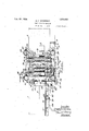
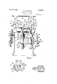
- Fig. 1 is a plan 'of the machine of my invention. Y
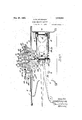
- Fig. 2 is a longitudinal vertical vsection therethrough.
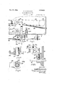
- Fig. 3 is an enlarged fragmentary plan ⁇ view, parts of the upper mechanism being re-V movedand other parts shown in section for better disclosure of the mechanism.
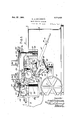
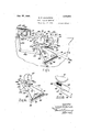
- Fig. 5 is a vertical transverse section through the machine.
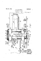
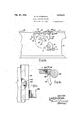
- Fig. 9 is afragmentary vertical section through the mount for the movable cutter spindle.
- Fig. 14 is a fragmentary elevationV of the rear side of the machine.
- Fig. 15 is a fragmentary plan vview with parts broken away and in section, showing the slide mount at .the rear edge of the front table section, and
- the table 1 is atwhat may be termed the front of the machine and table 2 is spaced a distance from the rear edge of the front'table.
- a horizontally located drive shaft 1 passes through the sides of the frame 8, at .one .end being equipped with a drive pulley 5 4adapted to bedri'ven from any suitable source of power by a belt 6.
- a pinion 7 is secured at the opposite end of the drive shaft and engages'v with a gear v8 mounted on a studshaft 9 secured to the rear side of the frame.
- a pinion 10 connected with gear 8 drives a relatively large gear 11 mounted von a stud shaft 12, connected with which gear 11 is a smaller gear 13 meshing with and driving two gears 11i of equal size mounted on stud shafts 15, as shown.
- Each of the gears 14e meshes with and drives two pinions 16 secured on the ends of shafts 17 which extend across the frame between the adjacent edges of the tables 1 and 2 and are mounted at their ends in suitable bearings 18.
- a roller 19 is carried on each shaft 1'?.
- rollers Two Aof the rollers are located close together at the rear edge of the front table 1 and the other two at the front edge of the rear table 2 and their upper lpoints are in substantially l.the same horizontal plane with the upper s ides of the tables. These rollers constitute .driven feed rollers for the boards entered into the machine. y
- a bar 13 is pivotally connected to each arm 86 of each bell-crank lever at the front side of the machine and extends across and downwardly to the lower end of the downturned portion l2 of the directly opposite bell-crank lever at the opposite side.
- Eyerods lll pass through the upper ends of the arms 36 and 39 of the directly opposite levers, being threaded at their outer ends to receive nuts, and strong coiled spring d5 connects the said rods at their inner ends.
- Y1 ⁇ his arrangement serves to cause the rollers 3lto be pressed downwardly through the force of the springs, and if one end of a roller is elevated with the passage of a board thereunder the. opposite end is also elevated through the passage of the arms 3? and t0 through the openings in the eye members 35 on blocks 32.
- the arrangement is an equalizing device capable of elevating one end of the roller 34 when the opposite end is elevated and workable within the slight limits required in the machine.
- a heavy vertical shaft 52 is rotatably mounted on which a forwardly extending heavy arm 58 is secured, at its forward end terminating in two journal ears 5l, one over the other in which a vertical spindle 55 is rotatably mounted, it being equipped with a cutter heat 56 at its upper end.
- a drive pulley 57 is formed on the spindle and is driven by a belt 58 from any motor, line shafting or the like.
- rEhe arm 53 is movable about the pivotal axis of shaft 52 and the spindle and cutter head carried at the forward inner end thereof may be moved to different positions relative to the other lined spindle and cutter, being normally drawn toward the same through a spring 59 attached to arm 53 and the end of the frame 8, as shown in Fig. 7.
- the two spindles 47 and 55 lie ene in front of the other and the two cutter heads 4-8 and 56 extend above the tables 1 and 2, lying between said tables and in sub- Stantially the same horizontal plane with eac-h other.
- a yoke 60 at the inner end of a fiat bar 61 is connected to the arm 53, lthe bar 61 cxtending horizontally'through an opening ⁇ in a block 62 connected to the back of the front side of the frame 3.
- a clamping block or har 63 also lies in said opening in block 62 against the upper side of the bar 61, as shown in Fig. 8, and a. screw 64. is threaded through the block 62 at its upperside to engage against the clamping member 63. A partial turn ot the screw 64e serves to clamp the bar 6l securely in place against movement.
- a gear 65 is secured, the same being; locatedV directlyvv over a rack segment 66 which is mounted on the end of a bar 67 located in front of the front side of trame 3 inclining ⁇ downwardly toward the rear end ot the machine.
- rack segment 66 is in alinement normally with additional rack teeth 68 cut in the upper edge of the bar near its upper end.
- rEhe segment 66 is adjustably.mounted on the bar, having depending sides 66L with a pin and slot connection with the bar and under the said segment a rubber cushion 69 is located, as shown in Fig. 13, so to permit a slight downward movement of the segment it'there -should not be perfect mesh of the rack and gear 65 at the time of their engagement.
- rlhe bar 67 At its lower end bar 67 is equippedwith a rod 7 0 which has slidable mounting in a kmember 71 carried by the front sideof the trame 3. rlhe bar 67 has a section cut away from its lower edge so as to leave a recessat the upper end of which is a shoulder 72, as shown.
- a supporting' bracket 108 is connected to the 'front end 21 of the open frame 'heretofore described and extends o-rward over the table 1 being!A turned downwardly at its free end toward the table.
- a rock shaft 109 is rotatably mounted at the end of the bracket and at eac-h end the rock shaft is equipped with a bell-crank lever comprising a vertical arm 110 and a rearwardly extending' horizontal arm 111, springs 112 being connected to the arms 110 and the end 21 of the open frame so as to normally move the arms 111 o'l" the levers in a downward direction.
- a shaft 13 with a roller 114e thereon is rotatably mounted on and between the ends ot the' arms 111 off the levers.
- the elevation of the roller 1111 does not talre place until after the end ott the board has passed between the first rollers 19 and 34:. lts release for return to lower position occurs with the release of the bar 67 as the board passes from over the linger 86, and in the meantime al succeeding' board may have been started over the table 1 and be partly under the roller ⁇ 114 which drops against it in time to move it to the said rollers 19 and Se, rollers, and help in the necessary elevation ot the rollers 341 for the passage of the board.
- A. machine of the class described comprising a support,- a Vfeed yand a VdeliveryV table carried by said support in a'linement and spaced apart at adjacentends, plurality of feed rollersrotatably mounted between the Iends of thetables, means for i positively driving the rollers, a plurality of spring pressed presser rollers located one over each feedrroller, a support for the presser rollers, an auxiliary feed roller Vcarried by the last named support and located over the feed table in front and above the first feed rollers, spring means tending to force said auxiliary feed roller in a downward direction, means for elevating the auxiliary feed roller against the force fof said spring means, cutters for dressing ythe edges ico Y of a board passed through the machine from f the feed to the v4delivery table, and lmeans extending above the plane of the tables
- a support a feedI and a delivery table carried thereby in alignment and spaced apart at their adjacent ends, feed means for boards located at said adjacent ends of the table, a relatively fixed rotatably mounted cutter located between the tables, a second cutter movab'ly mounted adjacent the iirst cutter, springmeans tending to move said second cutter toward said fist cutter, a bar slidably mounted transversely of the feed table, connections between said bar and the second cutter for moving the second cutter away from the first cutter on slidable movement of the bar in oney direction, a member adjustably mounted on said bar and adapted to be engaged by one edge of the board' as it is fed over the feed table, means on the feed table against which the opposite edge of the board bears whereby on movement of a board over the feed table said second eutter is moved away from the first cutter a distance depending upon the width of the board, and means mounted between the cut-v ters engaged by the boardV as the same passes between the Asam
- a feed table and a delivery table having ends spaced apart, means mounted adjacent the adjacent ends of' the table for carrying boards from the feed to the delivery table, a relatively fined rotatably mounted cutter for dressing one edge of the different boards, a second rotatableY cutter, a pivotally mounted arm on which the second cutter is mounted, said second cutter being adapted to dress the opposite edge of the board, a bar mounted transversely of and flush with the upper side of the feed table for slidable movements adjacent the feeding means, connections between said bar and the movable arm, mea-ns on said bar engaged by one edge of the board for slidably moving the bar when a board passes thereby, relatively lifted means on the feed table against which the opposite edge of the board bears, and means tor lock said movable arm againsty movement away from the edgel of the board; after it has once been moved to proper position to dress saidA edge of the board, said means being automatically operated by the board as its front end
Landscapes
- Life Sciences & Earth Sciences (AREA)
- Engineering & Computer Science (AREA)
- Mechanical Engineering (AREA)
- Wood Science & Technology (AREA)
- Forests & Forestry (AREA)
- Treatment Of Fiber Materials (AREA)
Description
Feb. 23 1926.
1,574,419 G. H. nl cKERsoN BOARD DRESSING MACHINE Filed Jan. 17, 1923 s sheets-sheet 1 @Hamam Feb. 23 1926. 1,574,419
- A G. H, DICKERSON BOARD DRESSING MACHINE Filed Jan. 17, 192s s sneetS-sheet s @nenn D' e Hmmm;
Feb. 23 1926. L 1,574,419 G H.UD|CKERSON l BOARD DRssNG MACHINEr Filed Jan'. 17, 1923- 8 Sheets-Sheet 4 Inuemor T5 Glennihckeron- I` 1,574,419 G. H. DICKERSON BOARD DRESSING' MACHINE Filed Jan. 17, 1925 8 Sheets-Sheet -6 'Gwnnhckerso i Feb. 23,`1926.- y 1",574,41'9 G. H..Dr|cKERso`N i BOARD DRES-SING MACHINE Filed Jan, 17, 1923 8 sheets-Sheet e Patented Feb. 23, 1925.
GLENN H. DICKERSQN, OF GRAND RAPIDS, MCHIGAN, ASSIGNOR OFIONE-THII-RD -'10 DE FOREST HAMILTON AND GNETHIRD-TO HENRY RIECI-IEL, BOTH yOIE GRAND RAPIDS, MICHIGAN.
BOARD-DRESSING MACHNE.
Application filed January 17, 1923. Serial No. 613,162.
To aZZ, whom t may concern.' Y
Be it known that I, GLENN H. Dickenson, a citizen of the United States of America,
residing at Grand Rapids, in the county of;
Kent and State of Michigan, have invented certain new and useful Improvements in Board-Dressing Machines; and 1 doV hereby declare the following to be a full, clear, and exact description of the invention, such as will enable others skilled in the art to which it appertains to make and use the same.
This invention relates to what is known as a glue j-oiner machine, being particularly concerned with a machine which dresses ory shapes the opposite edges of boards for subsequent gluing and joining` of the boards together. The present invention has for its primary object and purpose, a machine ir. which boards may be fed, one after the i effectively accomplishing this end, as 'will' fully appearV with understanding of the invention embodied in the construction which is illustrated in the accompanying drawings, in which,
Fig. 1 is a plan 'of the machine of my invention. Y
Fig. 2 is a longitudinal vertical vsection therethrough.
Fig. 3 is an enlarged fragmentary plan` view, parts of the upper mechanism being re-V movedand other parts shown in section for better disclosure of the mechanism.
Fig. 4l is an enlarged fragmentary side elevation of the machine looking at what may be termed the front side of the machine. n
Fig. 5 is a vertical transverse section through the machine.
Fig. 6 is a fragmentary elevation and section, on t-he plane lof linee- 6, Vof Fig. 5, looking in the direction, indicated bythe arrows. l. Y Y
Fig. 7 is an yenlarged fragmentary horirarn ortica.
zontal section through the machine at vthe front side and rearend yof the same. Y
Fig. 8 1s a fragmentary enlarged vertical section taken substantially on the plane of..`
line 8-8,.of F ig. 7.
Fig. 9 is afragmentary vertical section through the mount for the movable cutter spindle.
Fig. 10 is a horizontalsection taken on Y the plane of line 10V-10 of Fig. 9. e Fig. 11 is a fragmentary side eleva-tion `of the front side of the machine illustrating vthe position of the lock operatingmechanismV immediately after the entrance of a board to. the cutters.
Fig. 12 is a like view of the lock operating mechanism at a slightly later stage of the operation.
Fig. 13 is afragmentary sidel velevation and section of a detail of construction of the lock operating mechanism.
Fig. 14 is a fragmentary elevationV of the rear side of the machine.
Fig. 15 is a fragmentary plan vview with parts broken away and in section, showing the slide mount at .the rear edge of the front table section, and
Fig. 16 is a transverse vertical section` therethrough.
LikeV reference characters refer to: like f' parts in the dierent figures of the drawings.
1n the construction two horizontal tables 1 and 2 are supported in alinementonan under frame 3. The table 1 is atwhat may be termed the front of the machine and table 2 is spaced a distance from the rear edge of the front'table. A horizontally located drive shaft 1 passes through the sides of the frame 8, at .one .end being equipped with a drive pulley 5 4adapted to bedri'ven from any suitable source of power by a belt 6.
A pinion 7 is secured at the opposite end of the drive shaft and engages'v with a gear v8 mounted on a studshaft 9 secured to the rear side of the frame. A pinion 10 connected with gear 8 drives a relatively large gear 11 mounted von a stud shaft 12, connected with which gear 11 is a smaller gear 13 meshing with and driving two gears 11i of equal size mounted on stud shafts 15, as shown. Each of the gears 14e meshes with and drives two pinions 16 secured on the ends of shafts 17 which extend across the frame between the adjacent edges of the tables 1 and 2 and are mounted at their ends in suitable bearings 18. A roller 19 is carried on each shaft 1'?. Two Aof the rollers are located close together at the rear edge of the front table 1 and the other two at the front edge of the rear table 2 and their upper lpoints are in substantially l.the same horizontal plane with the upper s ides of the tables. These rollers constitute .driven feed rollers for the boards entered into the machine. y
An open frame comprising two parallel sides 20 and two parallel ends 21 is located over the feed rollers, shafts 22 screw threaded at their lower ends to enter su1ta-ble interiorly threaded guides 23 passing through the corners of the frame downwardly into the guides which are permaF nently secured to t-he front and rear sides of the frame 3. Each shaft at its upper end is equipped with a bevelled gear 24. A shaft 25 is located above and lengthwise of each side 2O of the open frame, being rotatably carried in sui-table brackets 26 attached to said open frame. Each shaft is equipped with -a bevelled pinion 27 adjacent each end which is in mesh with the adjacent gear 24 immediately below. A third shaftJ 28 lies above one of vthe ends 21 `of theopen frame, being rotatably mounted in brackets 29 and is likewise equipped 'with bevelled pinions 27a in mesh bracket including three parallel vertical guides 31 between which blocks 32 are mounted for vertical movements. The blocks serve as journals for the ends of cross shafts 88 on which rollers 34 are secured, one above each of the feed rollers 19. Each block y32 is formed with an integral upwardly eXtending eye member 85 lhaving' an opening therethrough.
Two bell-crank levers, each lncluding a vertical arm 36 and an inwardly extending horizontal arm 37 are pivotally mounted at 38 on eaeh'of the bracket guides at the front side of the machine, there being four of the bellvcrank levers at said front side. Similarly, an equal number of bell-crank levers are carried at the rear side. Each of the rear bell-crank levers includes a vertical arm 89 and an inwardly extending arm l0 and the same are pivotally mounted on and between the guides 31 at 41. Each of the arms 4-0 at its inner end is turned downwardly for av short distance, as indicated at 42.
A bar 13 is pivotally connected to each arm 86 of each bell-crank lever at the front side of the machine and extends across and downwardly to the lower end of the downturned portion l2 of the directly opposite bell-crank lever at the opposite side. Eyerods lll pass through the upper ends of the arms 36 and 39 of the directly opposite levers, being threaded at their outer ends to receive nuts, and strong coiled spring d5 connects the said rods at their inner ends. Y1`his arrangement serves to cause the rollers 3lto be pressed downwardly through the force of the springs, and if one end of a roller is elevated with the passage of a board thereunder the. opposite end is also elevated through the passage of the arms 3? and t0 through the openings in the eye members 35 on blocks 32. The arrangement is an equalizing device capable of elevating one end of the roller 34 when the opposite end is elevated and workable within the slight limits required in the machine.
At the front side of the frame 8, a heavy yoke t6 is secured having upper and lower arms and bearings therein for the rotatable mountof a vert-ical spindle 47, at the upper end of which a cutter head 48 is located. A drive pulley 4:9 is formed on the spindle and the same is driven by a belt 50 from any suitable source of power. This spindle is fixed except for its rot-ation and will hereafter be termed the i'iXed spindle and cutter.
Between .two lugs 51 projecting inwardly from'the rear end of the frame 3, a heavy vertical shaft 52 is rotatably mounted on which a forwardly extending heavy arm 58 is secured, at its forward end terminating in two journal ears 5l, one over the other in which a vertical spindle 55 is rotatably mounted, it being equipped with a cutter heat 56 at its upper end. A drive pulley 57 is formed on the spindle and is driven by a belt 58 from any motor, line shafting or the like. rEhe arm 53 is movable about the pivotal axis of shaft 52 and the spindle and cutter head carried at the forward inner end thereof may be moved to different positions relative to the other lined spindle and cutter, being normally drawn toward the same through a spring 59 attached to arm 53 and the end of the frame 8, as shown in Fig. 7. The two spindles 47 and 55 lie ene in front of the other and the two cutter heads 4-8 and 56 extend above the tables 1 and 2, lying between said tables and in sub- Stantially the same horizontal plane with eac-h other.
A yoke 60 at the inner end of a fiat bar 61 is connected to the arm 53, lthe bar 61 cxtending horizontally'through an opening `in a block 62 connected to the back of the front side of the frame 3. A clamping block or har 63 also lies in said opening in block 62 against the upper side of the bar 61, as shown in Fig. 8, and a. screw 64. is threaded through the block 62 at its upperside to engage against the clamping member 63. A partial turn ot the screw 64e serves to clamp the bar 6l securely in place against movement.
vAt the frontend oi one the shafts 17,
as shown in Fig. et, a gear 65 is secured, the same being; locatedV directlyvv over a rack segment 66 which is mounted on the end of a bar 67 located in front of the front side of trame 3 inclining` downwardly toward the rear end ot the machine. 'lhe rack segment 66 is in alinement normally with additional rack teeth 68 cut in the upper edge of the bar near its upper end. rEhe segment 66 is adjustably.mounted on the bar, having depending sides 66L with a pin and slot connection with the bar and under the said segment a rubber cushion 69 is located, as shown in Fig. 13, so to permit a slight downward movement of the segment it'there -should not be perfect mesh of the rack and gear 65 at the time of their engagement. At its lower end bar 67 is equippedwith a rod 7 0 which has slidable mounting in a kmember 71 carried by the front sideof the trame 3. rlhe bar 67 has a section cut away from its lower edge so as to leave a recessat the upper end of which is a shoulder 72, as shown.
Directly under the forward upper portion of the bar 67 a bell-crank lever comprising two arms 7 8 and 79 is pivotally mounted at 8O on the front side of the supporting frame 3, the arm 78 extending Vupwardly and forwardly and at'its end Carr)7n ing a block 78a against which the under edge t bar 67 rests. A. shaft 81, passes through the machine transversely a short-distance in front of the endet arm 78, on the front end ot which `an arm 82 is iixed'which ezttends downwardly to the arm .79, having a roller 83 at its free end which'is received in a cam slot 84 cut inthe arm. A spring 85 connects the end ot arm82 with the sta-V tionary` pivot of the bell-crank lever. On the shaft 81 a linger 86 is secured which normally,'at its upper end inte posesin the path of movement orp the board, indicated at B, as it passes from the front pairsof` rollers 19 and 34, moving it downwardly and roel;- ing the shaft-81.
This movement occurs as soon as the front end of the board comes to the finger 86, the
rocking ot the shaft 81, causes a movement of the arm 82 to the positionshown in Fig.
11, whereupon the bell-crank lever is tilted to elevate Athe arm 78 and raise the rack segment 66 into engagement with the continuously rotating gear 65. This causes the bar 67V to be moved longitudinally until the shoulder at 7 2 passes beyond the block 7 8a,
on which the bar is forced downwardly by spring 77 andthe'block 78a seated behind the shoulder, or the parts occupy the position shown in Figml. The rack is disengaged from the gear 65, and the clamping screw at has been turned so as to lock the bar 61 against movement. The arm 53 and the movable spindle and cutter head carried thereby are thereby positively locked against movement away from the board while itis passing between the cutters and its edges are being dressed or shaped.
lt isnecessary that the movable cutterbe properly located with reference to the sta- Y tionary cutter'to dress or shape the edges of the boards, and as the boards are oit yditlerent widths, this 'has to be done for each board entered into the machine. l have provided means -or accomplishing this VVautomatically.A lit is apparent that after the end of the board has passed the linger 869 said iinger is released and the parts relating to the locking ot the bar 60 come back to original position under the force oi springs 112, as later described, freeing the arm 53 for move-- ment. lilhen the board is entered into the machine, its rear edge bears against a guide shoe 87'v-.fhich is pivotally mounted between its ends at 88l on a slide bar 89 mounted for trar verse sliding.'movements atthe rear edge ot the front-table This shoe hasv aV short curved slot 96 therein, into which a pin 91 from the slide 89 extends. An adjustably mounted stop block 92 is carried by the shoe to limit its pivotal movement in onev direction, and a leaf spring 33 attached at one end to the pivot post 88 and at its other `end at 94tto the end of the 'shoe normally turns the shoe so as to bring theblock 9E' lee against 'the pii.. A strengthening' bar 88a is connected tothe pivot post 88 at one end and to the slide 89 at its other, as shown `in Fia'. 3.
To guide the board B into the machine at its opposite edge, an adjustably mounted guide bar 95 is carried on the upper side ot the table 1 parallel with the front side edge, said bar having' diagonally cut slots 96 therein through which headed pins 9'? pass into the table. in Varm 98 is pivotally mounted on a pin 99 carried by the'table, and an operating' arm or handle 169 is connected with the arm 98 so as to turn it.
rlhe free end of arm 98 extends over the bar 95 which is transversely slotted at 101 and a pin 102 extends trom the end of arm 98 into the slot. By operating the handle 100, a longitudinal movement is given to the guide bar 95 and the same is moved transversely in or out by reason oi the inclined slots at 96 bearing` against the pins 97.
lflilhen the board is entered into the machine, with One edge against the guide .bar 95, as soon as its opposite edge comes against the end of the shoe 87, .it is turned slightly about the pivot post or until the pin 91 comes against the end oi' the slot 90, and thereafter the shoe and attached slide bar 89 move laterally. 'lree sliding movementat the edpge of the `feed table 1, as shown in Figs. 15 and 16, the bar on its under side having longitudinal groove 103 cut therein with av rib 101i extending under the groove and seating` in a recess out in the table to receive it. Rollers 105 are mounted on the table to enter the groove 168 whereby the slide bar is mounted Jfor free anti-friction mo\ ement. An arm 196 is 'formed integral with the slide bar and extends downwardly and is curved to the rear, at its tree end beine; formed with a volte 167 which engages with a suitable collar 107'1'onthe spindle 55. The sliding` movement of the slide bar is imparted to the arm 58 through this connection with the spindle and the cutter 56 is moved to the proper position with reference to the board that it will dress the edge thereolc and remove no more than is necessary for the required dressing' or shaping. As soon as this adjustment of the movable cutter to place has occurred, the end or the board strikes the Enger 86 and starts the lock mechanism for the bar 61V in movement, almost instantly locking' the cutter against movement away 'from the board until after the board has passed whereupon the lock is released, as previously described, and the cutter carrying; arm 53 moved toward the front side ot the machine by spring` 59 so as to be ready 'for the action of the next board entered into the machine.
lt .is desirable that an auxiliary feed roller be used to engage against the upper side The bar is mounted for Y of the board to help its entrance between the rollers 19 and 34. A supporting' bracket 108 is connected to the 'front end 21 of the open frame 'heretofore described and extends o-rward over the table 1 being!A turned downwardly at its free end toward the table. A rock shaft 109 is rotatably mounted at the end of the bracket and at eac-h end the rock shaft is equipped with a bell-crank lever comprising a vertical arm 110 and a rearwardly extending' horizontal arm 111, springs 112 being connected to the arms 110 and the end 21 of the open frame so as to normally move the arms 111 o'l" the levers in a downward direction. A shaft 13 with a roller 114e thereon is rotatably mounted on and between the ends ot the' arms 111 off the levers.
A pinion 115 is located over and in mesh with the continuously rotating` gear 65 (see Fig. e) and a pulley 116 is either' 'formed integral with the pinion or permanently secured thereto. The pulley drives a belt 117 which passes around a second` pulley 118 tixed on the end of the shaft 118, whereby it is evident the roller 11eL is continuously driven and normally bears against the upper sides of boards ted into the machine to impel them to the rollers 19 and 34` On the end of the shaft 81 a lever 119 is secured a point between its ends, being formed with a part 120 which extends above the shaft 81 alongside ythe bar 67 so to be in the path ot movement of a pin 121 projecting laterally from the bar. A linlr bar 122 connects the lower` end of the lever 119 with an arm 123 which is fixed to the rock shaft 109 at its upper end and extends downwardly to its point oi connection to the linlr 122. When the bar 67 is given its longitudinal movement as the entering end of a board strikes the finger 86, pin 121 strikes against the part 120 to turn the lever 119 on the shaft 81 on which it is loosely mounted, this moving the link 122 for an operation of arm 123, thereby rocking the shaft 109 with a consequent elevation of the roller 114: above the board which lies beneath it. rlhis operation appears in the showing ot Fig. 11. The elevation of the roller 1111 does not talre place until after the end ott the board has passed between the first rollers 19 and 34:. lts release for return to lower position occurs with the release of the bar 67 as the board passes from over the linger 86, and in the meantime al succeeding' board may have been started over the table 1 and be partly under the roller` 114 which drops against it in time to move it to the said rollers 19 and Se, rollers, and help in the necessary elevation ot the rollers 341 for the passage of the board. rlhe operator does not have to force cntrance of the board between the rollers 19 and 84- as this entrance is automatically etserving` to torce the same between said Nin rected by the'rollery 114, and said roller 114 is moved upwardly out of the wayvso as to permit the placing of succeeding boards in the machine without the necessity of forcing the elevation of the rollerv 1111 against springs 112.
A movably mounted stop pin 125 normally held inwardly to the inner limit of its movement by a spring 124c ismounted on the front side of the supporting frame 8` to stop the movement of the arm 53 under the influence of spring 59. This insures against the movable cutter coming too close to the fixed cutter. j Y
This construction lof glue joiner machine is practical and has proved its merit in severe test. l/Vith it both side edges of a board may be dressed or shaped simultaneously ready for the application of glue and subsequent clamping together. The cutters may be of any preferred type so as to either plan-e the edges of the boards or to provide them with tongue and groove or other type of joint wanted. Any width of boards be tween the narrowest and the widest which vthe machine will take may be fed into the sameand the cutters will automatically take the required .positions with respect 'thereto and the inovably mounted cutterwill be automatically locked against movement away from the board until after the dressing of the .edges thereof has been completed,
the lock immediately thereafter becoming ineffective. The. machine may be almost instantly changed for different thicknesses of boards. The construction is practical and complete in every way. The invention is defined in the appended claims and l consider myself entitled to all forms of structure coming within their scope.
I claim:
1. In a machine of the class described, a
support, a feed and a delivery table carriedv `nected to the arm extending laterally therefrom, va block through which the arm passes, a clampingmember carried in the block and bearing againstv the bar, a screw for clamping said member against the bar, a gear ro-V Y j tatable with one ofthe feed rollers, a bar formed with a rack section thereon located adjacent the gear, a bar extending from the` in combination definedin claim 1, combined with meansfor freeing the rack barfromy longitudinal movement sufcient to turn thel zoA screw to clamping position, means for lioldv-` ing the rack bar againstreturn to original position when freed from the gear, and
means for 'moving said holding means to inoperative position o n passage of the boa-rd past the cutters, Y i 1. A. machine of the class described, comprising a support,- a Vfeed yand a VdeliveryV table carried by said support in a'linement and spaced apart at adjacentends, plurality of feed rollersrotatably mounted between the Iends of thetables, means for i positively driving the rollers, a plurality of spring pressed presser rollers located one over each feedrroller, a support for the presser rollers, an auxiliary feed roller Vcarried by the last named support and located over the feed table in front and above the first feed rollers, spring means tending to force said auxiliary feed roller in a downward direction, means for elevating the auxiliary feed roller against the force fof said spring means, cutters for dressing ythe edges ico Y of a board passed through the machine from f the feed to the v4delivery table, and lmeans extending above the plane of the tables into thepath of movement of the board for. yopleratingsaid elevating means and holdingA the lauxiliary feed roller elevated until the board has passed .by said last Ymentioned means. Y
5. A machine of the class described, comprising a support, a feed and a delivery table carried by said. support inalinement and spacedapart at adjacent ends, a plu` rality of feed rollers rotatably mounted between the ends of the tables, means for driving t-he feed rollers, a second support over the tables, a plurality of spring pressed rollersV vcarried by the Ysecond support, one above each feed roller, a bracketk extending from the ysecond support over the feed table, a rock shaftv mounted thereon, bell crank levers on vthe roclrvshaft, a, shaft passing throughone of the arms of each lever, a roller ont-he shaft, springs attached to the other arms ofthe levers tendingto force the roller downwardly, means for driving the last mentioned roller, a shaft mounted transversely through the first support, a finger extending therefrom to between and vabove the tables, an arm connected to the rock shaft, a lever loosely mounted on the last named shaft, a link connecting the arm and lever, agear connected with one of the feed rollers and rotating therewith, a rack bar, means for elevating the rack bar into engagement with the gear on depression of the linger, means for disconnecting the rack bar from the gear after it has moved longitudinally a predetermined distance, means for holding the rack bar in the position to which moved after disconnection from the gear, said means being freed on elevation of the linger, and means for operating the said last' mentioned lever by the movement of the rack bar to elevate the auxiliary roller by rocking of the rock shaft and holding it elevated until the rack bar is released.
6. A constructioncontaining the elements in combination. defined iny claiml 5, Vcombined with cutters for dressing the edges of a board passing from the feed table to the delivery table between the first feed and the presser rollers, said board serving to depress the said' linger on reaching the same and release it for elevation on passing therefrom.
7. A construction containing the elements in combination deined in claim 5, combined with a relatively lined rotatably mounted cutter and a movable* rotatablyT mountedI cutter, mea-ns to adjust the movable cutterV to a distance away fromV the first' cutter slightlyy less than the width of the board passed from the feed to the delivery table, and locking means operated by the movement ofthe rack bar to lock the movable cutter in fixed position until the rack bar is released, substantially as described;
8.r In a machine of thev class described, a feed* and a delivery table loca-ted end to end and spaced apart at adjacent ends, a cutter mounted to turn ony a vertical axis located between the tables and being relatively fixedy against movement, an elongated supporting arm mounted at one end for pivotal movement on and under the delivery table and extending to between the tables, a second cutter rotatably1 mounted to turn on a vertical axis at the free end of the arm, spring means connected to the arm tending to move the second cutter. toward the iirst cutter, a Vbar slidablyV mounted flush with the upper surface of theV feed table at the inner end thereof, a rigid connection between said bar and the supporting arm at the free end of said arm, and a member secured' to the upper side of said bar and located at an angle to the length of the feed table against which a board ridesv at one edge when fed to the cutters thereby automatically moving the second cutter to proper position with reference to the edge of the board, combined with a guide on the feed table for the opposite edge of said board.
9. In a machine of the class described, a support, a feedI and a delivery table carried thereby in alignment and spaced apart at their adjacent ends, feed means for boards located at said adjacent ends of the table, a relatively fixed rotatably mounted cutter located between the tables, a second cutter movab'ly mounted adjacent the iirst cutter, springmeans tending to move said second cutter toward said fist cutter, a bar slidably mounted transversely of the feed table, connections between said bar and the second cutter for moving the second cutter away from the first cutter on slidable movement of the bar in oney direction, a member adjustably mounted on said bar and adapted to be engaged by one edge of the board' as it is fed over the feed table, means on the feed table against which the opposite edge of the board bears whereby on movement of a board over the feed table said second eutter is moved away from the first cutter a distance depending upon the width of the board, and means mounted between the cut-v ters engaged by the boardV as the same passes between the Asame and automatically operated thereby, combined with locking means associated with said movable cutters to automatically operate said locking means to loclr the movable cutters against movement away from the board during the time that the board is passing between theI cutters.
' l0. ln a. machine of the class described, a feed table and a delivery table having ends spaced apart, means mounted adjacent the adjacent ends of' the table for carrying boards from the feed to the delivery table, a relatively fined rotatably mounted cutter for dressing one edge of the different boards, a second rotatableY cutter, a pivotally mounted arm on which the second cutter is mounted, said second cutter being adapted to dress the opposite edge of the board, a bar mounted transversely of and flush with the upper side of the feed table for slidable movements adjacent the feeding means, connections between said bar and the movable arm, mea-ns on said bar engaged by one edge of the board for slidably moving the bar when a board passes thereby, relatively lifted means on the feed table against which the opposite edge of the board bears, and means tor lock said movable arm againsty movement away from the edgel of the board; after it has once been moved to proper position to dress saidA edge of the board, said means being automatically operated by the board as its front end reaches a position between the cutters, substantially as described.
In testimony whereof I affix' my signature.
GLENN H. DICKERSCN.
Priority Applications (1)
| Application Number | Priority Date | Filing Date | Title |
|---|---|---|---|
| US613162A US1574419A (en) | 1923-01-17 | 1923-01-17 | Board-dressing machine |
Applications Claiming Priority (1)
| Application Number | Priority Date | Filing Date | Title |
|---|---|---|---|
| US613162A US1574419A (en) | 1923-01-17 | 1923-01-17 | Board-dressing machine |
Publications (1)
| Publication Number | Publication Date |
|---|---|
| US1574419A true US1574419A (en) | 1926-02-23 |
Family
ID=24456126
Family Applications (1)
| Application Number | Title | Priority Date | Filing Date |
|---|---|---|---|
| US613162A Expired - Lifetime US1574419A (en) | 1923-01-17 | 1923-01-17 | Board-dressing machine |
Country Status (1)
| Country | Link |
|---|---|
| US (1) | US1574419A (en) |
-
1923
- 1923-01-17 US US613162A patent/US1574419A/en not_active Expired - Lifetime
Similar Documents
| Publication | Publication Date | Title |
|---|---|---|
| US1574419A (en) | Board-dressing machine | |
| GB315692A (en) | Improvements in or relating to sheet delivery apparatus | |
| US2150527A (en) | Feeding mechanism for sewing machines | |
| US1638310A (en) | Board kicker for end-matching machines | |
| US1903268A (en) | Machine and method for sewing buttons onto fabric or the like | |
| US892602A (en) | Match-making machine. | |
| US886126A (en) | Mechanism for replacing weft units. | |
| US1318851A (en) | Qiqqki | |
| US1880002A (en) | Drawing roll mechanism | |
| US1600656A (en) | Woodworking-machine feed mechanism | |
| US245608A (en) | John j | |
| US1300446A (en) | Loader for buttonhole-machines. | |
| US1460184A (en) | Shirt board for ironing machines | |
| US1442630A (en) | Slicing machine | |
| US2156558A (en) | Cover feeding and folding mecha | |
| US1603928A (en) | Typewriting machine | |
| US1462521A (en) | Stitching mechanism | |
| US1387545A (en) | Tobacco stem rolling and leaf booking machine | |
| US245187A (en) | Wood-bending machine | |
| US2387282A (en) | Tie sewing machine | |
| US1569909A (en) | Feeding mechanism for book-sewing machines | |
| US1436397A (en) | Paper-feeding mechanism for typewriting machines | |
| US1529284A (en) | Ironing machine | |
| US648114A (en) | Apparatus for grooving and cutting wood. | |
| US1458026A (en) | Laying-on apparatus for book-fastening machines |