US1563122A - Portable amusement riding device - Google Patents
Portable amusement riding device Download PDFInfo
- Publication number
- US1563122A US1563122A US529057A US52905722A US1563122A US 1563122 A US1563122 A US 1563122A US 529057 A US529057 A US 529057A US 52905722 A US52905722 A US 52905722A US 1563122 A US1563122 A US 1563122A
- Authority
- US
- United States
- Prior art keywords
- section
- tower
- shaft
- base
- posts
- Prior art date
- Legal status (The legal status is an assumption and is not a legal conclusion. Google has not performed a legal analysis and makes no representation as to the accuracy of the status listed.)
- Expired - Lifetime
Links
Images

Classifications
-
- A—HUMAN NECESSITIES
- A63—SPORTS; GAMES; AMUSEMENTS
- A63G—MERRY-GO-ROUNDS; SWINGS; ROCKING-HORSES; CHUTES; SWITCHBACKS; SIMILAR DEVICES FOR PUBLIC AMUSEMENT
- A63G1/00—Roundabouts
- A63G1/28—Roundabouts with centrifugally-swingable suspended seats
Definitions
- Thisinvention relates to a type of amusement device commonly known as a circle swing, in which a number of freely suspended cars move in a common circular path,
- the invention has for its object to provide a portable riding device of this type, in which the various parts may be compact ly assembled for transportation purposes.
- Fig. 1 of the drawings is a side elevation of a device embodying the invention, the cars being omitted, and certain parts being broken away. Y
- Fig. 2 is an enlarged fragmentary central vertical section at right angles to Fig. l.
- Fig. 3 is a detail ⁇ horizontal sectional view taken on the line 3-3 of Fig. 2.
- Fig. 1 is a detail horizontal sectional view taken along the line 4;-4 of Fig. 1. v
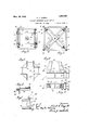
- Fig. 5 is a diagrammatic plan view showing the arrangement of the removable base supports and braces.
- Fig. G is a fragmentary plan view, partly in section, of one of the base supports.
- Fig. 7 is a fragmentary side view of the base supports. y y
- Fig. 8 is an enlarged fragmentary side view showing the lower portion of the tower andthe means for securing it to the base.
- Fig. 9 is a horizontal section on the line 9.9 of Fig. 8.
- the device comprises, briefly, a vertical sectional shaft carrying radiating arms at its upper end, from which the cars are suspended, a telescopic tower to support and brace the shaft, and a base carrying the tower and the drive rmechanism for .revolving theshaft, this base being preferably permanently mounted on a transportatlon wagon.
- Iand comprises an outer lower section of frusto-pyramidal form made up of corner
- the tower is here shown as of square form v braces 11 and 12.
- This outer section encloses and rigidly supports a straight sided square inner section made up of corner posts 13 joined by horizontalv 14 and 15.
- This inner section fits snugly within the top part of the outer lower secp tion and is braced at points throughout its length by diagonal braces 16 which Vextend between the posts 10 and 13.
- the posts of the different tower sections are preferably made of angle bars and the bracing members 1st and 15 for the inner section are secured to the outer faces of the posts 13, which latter' present smooth inner faces serving as guides for the top or telescopic section.
- This telescopic upper idal form except at its prises angle-bar corner posts 18 united by horizontal and diagonal braces 19 and 20. At their lower ends these posts 18 are bent to ⁇ present relatively short vertical portions 18 which lit snugly and slidably within the posts 13 of the guidesection. At their upper ends the posts 18 fit within and are secured to a cap 21 which forms the top bearing for the shaft.
- a pair of hand winches 22, of the usual construction are Vmounted on opposite sides of the outer lower tower section, cables 23 leading upwardly from these winches over pulleys 24 mounted on the upper end of the lower section, downward around pulleys 25 on the bottom of the telescopic sec tion and upward to connect to eyes 26 fixed on the top of the lower section.
- the telescopic section may beheld in its raised position by suit-able bolts passed throughthe members '13 and 18.
- the vertical car-supporting shaft is made up of three sections, a top section 28, an intermediate section 29, and a bottom section 30, the intermediate section 29 being unitedA to the othersections by interlocking.clutch elements 31 so thatit may be readily re ment of the upper tower section.
- a socket' head 32 For supporting the cars, a socket' head 32 Y the inner ends of rigid arms 34;.' which radfv and diagonal braces l moved, the length of this section corre' spending to the length' of telescopic move# till ate therefrom and are provided with caps fitting ⁇ freely over their outer ends.
- Tie rods 36 lead from these caps to a flanged member 37 fixed on the upper end of the shaft 28 (Fig. 2), these rods having hooked inner ends detachably engaging; ⁇ in holes 38 in the member 37.
- the caps 35 at the outer end of arms 3i have holes 3S) formed therein to r-eceive the upper ends of the rods from which the cars are suspended.
- the lower section 3() of the shaft which is comparatively short, seats in a socket bearing;l 4t() bolted to the base of the device.
- This base is indicated generally by 4l and may be of any suitable construction, the supportingwagon, indicated generally by 4t2, being here shown with a flat Hoor 43, on which the base 41 rests.
- each of the front castings 44' are formed with an eye-lug t8 at its lower end through which is inserted a bolt 49 carried in brackets 50 fixed to base 41.
- Jetlthomegh the wagon 2 remains under the tower when the device is in use, the weight is carried ⁇ independently of the wagon running gear, by a removable substructure.
- This substructure comprises a number of columns 52, which are of a height to reach from the wagon flooring;- 43 to the ground, four of which are positioned one under cach corner of the tower and a fifth in the centre, as shown in Fig. 5.
- These buttress members 53 are removably secured to the respective corner columns 52 by means of rods ,54 (Fie.
- struts 57 (Fig. l) which are connected at their upper ends to the tower posts 1Q. These struts 57 may be removably secured to the tower posts 10 and members 5.3 by means of pins 58 passing through the ends thereof and through ears 59 fixed to said posts l() and members 53.
- the members 53 may be secured together by means of tie rods 60, arranged as indicated in Fig. 5, while the columns 52 may be likewise braced by tie rods (il. rlhese tie rods 60 and (il may be secured to the columns 52 and members 53 in any suitable manner, such as indi fated in Figs. 6 and 7, by brackets and (i3, rcsi'iectively, which arc secured to the column 52 and member 53 and receive pins (i5 and G4 passed through the ends of the tie rods 60 and 6l., respectively.
- the car supporting ⁇ shaft may be rotated by any suitable mechanism, a ,gas engine G7 being;- here shown as mounted on the base lll and connected to a short horizontal shaft 63 by a belt 69, the shaft G8 beine ⁇ connected to the shaft section 30 by suitable reducingT gearing. including the bevel gear and pinion indicated at in Fig. 2, a combined brake and clutch 7l of ordinary construction be ingr provided on shaft 68.
- the car supporting shaft is preferably braced at points alongits length by means of bearing' sleeves 72, which are fixed on crossed braces 73, removably secured to the tower at their outer ends.
- the upper telescopic tower section is [rst raised by the winches 22 to permit of removal of the intermediate shaft section 2i) and is then lowered into the lower tower section, the car supporting' elements 34, 36 being removed.
- the columns 52 and bracing members 53 and 57 are then removed.
- the bolts i-5 which secure the tower posts 10 to the base il are then loosened, permitting the collapsed tower to be swung' on the hinge bolts 49 to a horizontal position, its outer end resting on a second wagon placed in front of the wagon 42. ln assemblingr the tower, the above operations are reversed.
- a portable device of this class which may be readily moved from place to place and set up easily and quickly in a simple manner.
- Vhat l' claim is:
- a portable riding device comprising a if'ertical shaft having,Y a. removable section, car-supporting means mounted on said shaft, a tower forming an upper bearing for said shaft and comprising upper and lower seotions, said lower section having; a plurality of guides co-operating with said upper section for pe mitting telescoping of said upper and lower sections upon removing; the section of the shaft.
- a portable riding device comprising' a vertical shaft, car supporting means mounted thereon, a tower forming an upper bearing for said shaft, said tower comprising upper and lower sections, the upper section being teleseopically mounted in a plurality lill) lio ol parallel guides' carried by said lower section, said shaft comprising upper, lower and intermediate sections, the said intermediate lsection being removable to permit telescoping of the tower sections.
- a portable riding device comprising a vertical shaft having a removable intermediate section, car supporting means mounted thereon, a bearing tower for said shaft comprising a lower section having inclined walls, a parallel sided guide element lixed within the said lower section, and an upper section adapted for vertical adjustment in said guide element.
- a portable riding device comprising a vertical shaft, car supporting means mounted thereon, a tower comprising a lower section having inclined walls, a parallel sided guide element fixed in said lower section, an upper section adapted for vertical movement in said guide element, and means-for raising said upper section and holding it in raised position, said means comprising a pair oi' Winches mounted on opposite sides of the lower section, and cables leading from said winches around pulleys on the upper end of the lixed section and the lower end ol? the telescopio section, said cables' being attached at their ends to the top of the lower sectioi'i.
- A. portable riding device comprising a 'vertical shajlt having a removable section, a bearing tower for said sh ait comprising up-: per and lower sections, said lower section having a plurality of parallel guiding members mounted therein co-operating with said upper section for permitting telescoping of the upper and lower Sections' upon removal of said section of the shaft, a base support ing said tower, means for hinging said tower on one side thereof to said base, and mechanism 'for rotating said shaft located Within said lower tower section.
- a portable riding device comprising a vertical sectional shaft, a telescopic towel' forming an upper' bearing for said shaft, a base for said tower, a wagon on which said base is iixed, and removable columns positioned under the corners of the base to support the same .independently of the running gear of the wagon.
- a portable ridingl device comprising a vertical sectional shaft, a telescopic tower forming an upper bearing for said shaft, a base for said tower, a series of columns po ⁇ sitioned under the corners ot the base, and buttress members extending outwardly from and removably connected to said columns.
- a portable riding device comprising a vertical sectional shaft, a telescopic tower forming an upper bearing for said shaft, a base for said tower, a wagon on which said base is lixed, a series ot columns removably engaged under said base, buttress members extending outwardly from and removably connected to said columns, and removable struts extending upwardly and inwardly from the said buttress members to the sides oi,B the said tower.
Description
n l t l. w 3 h 6 q u 5, l h s. 2 E c I v E D 6% ...mw LD EMS. um@ mm LmwJ d Fm wm.. B A 4mi R o D.. 5 2 9 1 4 2 v., o 9 N 3 lu/vento@ @2M 4' emma,
Nov. 24, 1925- 1,563,122
F. L. L !ZZELL PORTABLE AMUSEMENT RIDING DEVICEL Filed Jan. 13. 1,922 2 Sheets-Sheet 2 5 64 1./ I I vantoz fd" I l? MZW 62 m1,@ www A posts 10 joined by horizontal and. inclined` lPatented Nov. 24, 1925.
FRANK L. UZZELL, OF JAMAICA, NEW YORK.
fg `j PORTABLE AMUSEMENT RIDING DEvI'eE.
Application filed January 13, 1922. Serial No. 529,057.
To ZZ 107mm t may concer/n.'
Be it known that I, FRANK L. UzznLL, citizen of the United States, and resident of Jamaica, in the county of Queens and State of New York, have invented certain' new and useful Improvements in Portable Amusement Riding Devices, of which the following is` a specification.
Thisinvention relates to a type of amusement device commonly known as a circle swing, in which a number of freely suspended cars move in a common circular path,
The invention has for its object to provide a portable riding device of this type, in which the various parts may be compact ly assembled for transportation purposes.
In the accompanying drawings I have illustrated a preferred en'lbodiment of the invention.
Fig. 1 of the drawings is a side elevation of a device embodying the invention, the cars being omitted, and certain parts being broken away. Y
Fig. 2 is an enlarged fragmentary central vertical section at right angles to Fig. l.
Fig. 3 is a detail `horizontal sectional view taken on the line 3-3 of Fig. 2.
Fig. 1 is a detail horizontal sectional view taken along the line 4;-4 of Fig. 1. v
Fig. 5 is a diagrammatic plan view showing the arrangement of the removable base supports and braces.
Fig. G is a fragmentary plan view, partly in section, of one of the base supports.
Fig. 7 is a fragmentary side view of the base supports. y y
Fig. 8 is an enlarged fragmentary side view showing the lower portion of the tower andthe means for securing it to the base.
Fig. 9 is a horizontal section on the line 9.9 of Fig. 8.
As here shown, the device comprises, briefly, a vertical sectional shaft carrying radiating arms at its upper end, from which the cars are suspended, a telescopic tower to support and brace the shaft, anda base carrying the tower and the drive rmechanism for .revolving theshaft, this base being preferably permanently mounted on a transportatlon wagon.
Iand comprises an outer lower section of frusto-pyramidal form made up of corner The tower is here shown as of square form v braces 11 and 12. This outer section encloses and rigidly supports a straight sided square inner section made up of corner posts 13 joined by horizontalv 14 and 15. This inner section fits snugly within the top part of the outer lower secp tion and is braced at points throughout its length by diagonal braces 16 which Vextend between the posts 10 and 13. Y
The posts of the different tower sections are preferably made of angle bars and the bracing members 1st and 15 for the inner section are secured to the outer faces of the posts 13, which latter' present smooth inner faces serving as guides for the top or telescopic section.
This telescopic upper idal form except at its prises angle-bar corner posts 18 united by horizontal and diagonal braces 19 and 20. At their lower ends these posts 18 are bent to `present relatively short vertical portions 18 which lit snugly and slidably within the posts 13 of the guidesection. At their upper ends the posts 18 fit within and are secured to a cap 21 which forms the top bearing for the shaft.
section is of pyramlower end and com- For raising and lowering the telescopicsection, a pair of hand winches 22, of the usual construction, are Vmounted on opposite sides of the outer lower tower section, cables 23 leading upwardly from these winches over pulleys 24 mounted on the upper end of the lower section, downward around pulleys 25 on the bottom of the telescopic sec tion and upward to connect to eyes 26 fixed on the top of the lower section. The telescopic section may beheld in its raised position by suit-able bolts passed throughthe members '13 and 18.
The vertical car-supporting shaft is made up of three sections, a top section 28, an intermediate section 29, and a bottom section 30, the intermediate section 29 being unitedA to the othersections by interlocking.clutch elements 31 so thatit may be readily re ment of the upper tower section.
For supporting the cars, a socket' head 32 Y the inner ends of rigid arms 34;.' which radfv and diagonal braces l moved, the length of this section corre' spending to the length' of telescopic move# till ate therefrom and are provided with caps fitting` freely over their outer ends. Tie rods 36 lead from these caps to a flanged member 37 fixed on the upper end of the shaft 28 (Fig. 2), these rods having hooked inner ends detachably engaging;` in holes 38 in the member 37. The caps 35 at the outer end of arms 3i have holes 3S) formed therein to r-eceive the upper ends of the rods from which the cars are suspended. These cars and theiil suspension rods have not been shown in the drawings, as they may be of any desired construction and do not form part of the present invention.
The lower section 3() of the shaft, which is comparatively short, seats in a socket bearing;l 4t() bolted to the base of the device. This base is indicated generally by 4l and may be of any suitable construction, the supportingwagon, indicated generally by 4t2, being here shown with a flat Hoor 43, on which the base 41 rests.
To secure the tower posts 10 to the base fil, the former are fixed. on ,that side of the tower which is above the rear end of the wagon, to castings such as 44 (Figs. 8-9) and on the side above the front end of the wagon to castings such as 44V, the castings Liet and all being in the main of like construction and being all secured to tbe base il by means of bolts 5 projecting upwardly f from the base 4]. and having threaded thereon nuts 6 bearing on bottom flanges 47 on the casting L14. To facilitate the removal of the tower from the base for transportation` each of the front castings 44' are formed with an eye-lug t8 at its lower end through which is inserted a bolt 49 carried in brackets 50 fixed to base 41.
Jetlthomegh the wagon 2 remains under the tower when the device is in use, the weight is carried` independently of the wagon running gear, by a removable substructure. This substructure comprises a number of columns 52, which are of a height to reach from the wagon flooring;- 43 to the ground, four of which are positioned one under cach corner of the tower and a fifth in the centre, as shown in Fig. 5. Extending outwardly from these columns, in the manner indicated in Fig. 5, are a series of buttress members 53 which increase the base areaof the tower and brace the latter aga-inst tiltingr movement. These buttress members 53 are removably secured to the respective corner columns 52 by means of rods ,54 (Fie. 7), which are passed downwardly through eyemembers, 55 and 5,6, respectively fixed on the columns 52 and members 53. Extending upwardly and inwardlyfrom the outer ends of these buttress members 53 are struts 57 (Fig. l) which are connected at their upper ends to the tower posts 1Q. These struts 57 may be removably secured to the tower posts 10 and members 5.3 by means of pins 58 passing through the ends thereof and through ears 59 fixed to said posts l() and members 53.
The members 53 may be secured together by means of tie rods 60, arranged as indicated in Fig. 5, while the columns 52 may be likewise braced by tie rods (il. rlhese tie rods 60 and (il may be secured to the columns 52 and members 53 in any suitable manner, such as indi fated in Figs. 6 and 7, by brackets and (i3, rcsi'iectively, which arc secured to the column 52 and member 53 and receive pins (i5 and G4 passed through the ends of the tie rods 60 and 6l., respectively.
The car supporting` shaft .may be rotated by any suitable mechanism, a ,gas engine G7 being;- here shown as mounted on the base lll and connected to a short horizontal shaft 63 by a belt 69, the shaft G8 beine` connected to the shaft section 30 by suitable reducingT gearing. including the bevel gear and pinion indicated at in Fig. 2, a combined brake and clutch 7l of ordinary construction be ingr provided on shaft 68. The car supporting shaft is preferably braced at points alongits length by means of bearing' sleeves 72, which are fixed on crossed braces 73, removably secured to the tower at their outer ends.
In dismantlingthe swingT for transporta-- tion, the upper telescopic tower section is [rst raised by the winches 22 to permit of removal of the intermediate shaft section 2i) and is then lowered into the lower tower section, the car supporting' elements 34, 36 being removed. The columns 52 and bracing members 53 and 57 are then removed. The bolts i-5 which secure the tower posts 10 to the base il are then loosened, permitting the collapsed tower to be swung' on the hinge bolts 49 to a horizontal position, its outer end resting on a second wagon placed in front of the wagon 42. ln assemblingr the tower, the above operations are reversed.
It will be seen that a portable device of this class is provided which may be readily moved from place to place and set up easily and quickly in a simple manner.
Vhat l' claim is:
l. A portable riding device comprising a if'ertical shaft having,Y a. removable section, car-supporting means mounted on said shaft, a tower forming an upper bearing for said shaft and comprising upper and lower seotions, said lower section having; a plurality of guides co-operating with said upper section for pe mitting telescoping of said upper and lower sections upon removing; the section of the shaft.
2. A portable riding device comprising' a vertical shaft, car supporting means mounted thereon, a tower forming an upper bearing for said shaft, said tower comprising upper and lower sections, the upper section being teleseopically mounted in a plurality lill) lio ol parallel guides' carried by said lower section, said shaft comprising upper, lower and intermediate sections, the said intermediate lsection being removable to permit telescoping of the tower sections.
3. A portable riding device comprising a vertical shaft having a removable intermediate section, car supporting means mounted thereon, a bearing tower for said shaft comprising a lower section having inclined walls, a parallel sided guide element lixed within the said lower section, and an upper section adapted for vertical adjustment in said guide element.
4. A portable riding device comprising a vertical shaft, car supporting means mounted thereon, a tower comprising a lower section having inclined walls, a parallel sided guide element fixed in said lower section, an upper section adapted for vertical movement in said guide element, and means-for raising said upper section and holding it in raised position, said means comprising a pair oi' Winches mounted on opposite sides of the lower section, and cables leading from said winches around pulleys on the upper end of the lixed section and the lower end ol? the telescopio section, said cables' being attached at their ends to the top of the lower sectioi'i.
5. A. portable riding device comprising a 'vertical shajlt having a removable section, a bearing tower for said sh ait comprising up-: per and lower sections, said lower section having a plurality of parallel guiding members mounted therein co-operating with said upper section for permitting telescoping of the upper and lower Sections' upon removal of said section of the shaft, a base support ing said tower, means for hinging said tower on one side thereof to said base, and mechanism 'for rotating said shaft located Within said lower tower section.
6. A portable riding device comprising a vertical sectional shaft, a telescopic towel' forming an upper' bearing for said shaft, a base for said tower, a wagon on which said base is iixed, and removable columns positioned under the corners of the base to support the same .independently of the running gear of the wagon.
7. A portable ridingl device comprising a vertical sectional shaft, a telescopic tower forming an upper bearing for said shaft, a base for said tower, a series of columns po` sitioned under the corners ot the base, and buttress members extending outwardly from and removably connected to said columns.
8. A portable riding device comprising a vertical sectional shaft, a telescopic tower forming an upper bearing for said shaft, a base for said tower, a wagon on which said base is lixed, a series ot columns removably engaged under said base, buttress members extending outwardly from and removably connected to said columns, and removable struts extending upwardly and inwardly from the said buttress members to the sides oi,B the said tower.
Signed at New York city, in the county of New York and State of New York this tenth day of January, A.. D. 1922.
FRANK L. UZZELL.
Priority Applications (1)
| Application Number | Priority Date | Filing Date | Title |
|---|---|---|---|
| US529057A US1563122A (en) | 1922-01-13 | 1922-01-13 | Portable amusement riding device |
Applications Claiming Priority (1)
| Application Number | Priority Date | Filing Date | Title |
|---|---|---|---|
| US529057A US1563122A (en) | 1922-01-13 | 1922-01-13 | Portable amusement riding device |
Publications (1)
| Publication Number | Publication Date |
|---|---|
| US1563122A true US1563122A (en) | 1925-11-24 |
Family
ID=24108323
Family Applications (1)
| Application Number | Title | Priority Date | Filing Date |
|---|---|---|---|
| US529057A Expired - Lifetime US1563122A (en) | 1922-01-13 | 1922-01-13 | Portable amusement riding device |
Country Status (1)
| Country | Link |
|---|---|
| US (1) | US1563122A (en) |
Cited By (4)
| Publication number | Priority date | Publication date | Assignee | Title |
|---|---|---|---|---|
| DE3224640A1 (en) * | 1982-07-01 | 1984-01-05 | Schallmair, Karl, 8904 Friedberg | Hammer-type strength tester |
| US5564983A (en) * | 1994-02-02 | 1996-10-15 | Larson; Walter F. | Tower ride |
| US5957779A (en) * | 1996-10-08 | 1999-09-28 | Larson; Walter F. | Tower |
| US9057195B2 (en) | 2008-05-22 | 2015-06-16 | Sunrun South Llc | Camming clamp for roof seam |
-
1922
- 1922-01-13 US US529057A patent/US1563122A/en not_active Expired - Lifetime
Cited By (5)
| Publication number | Priority date | Publication date | Assignee | Title |
|---|---|---|---|---|
| DE3224640A1 (en) * | 1982-07-01 | 1984-01-05 | Schallmair, Karl, 8904 Friedberg | Hammer-type strength tester |
| US5564983A (en) * | 1994-02-02 | 1996-10-15 | Larson; Walter F. | Tower ride |
| US5957778A (en) * | 1994-02-02 | 1999-09-28 | Larson; Walter F. | Tower ride |
| US5957779A (en) * | 1996-10-08 | 1999-09-28 | Larson; Walter F. | Tower |
| US9057195B2 (en) | 2008-05-22 | 2015-06-16 | Sunrun South Llc | Camming clamp for roof seam |
Similar Documents
| Publication | Publication Date | Title |
|---|---|---|
| US2227310A (en) | Basket-ball backstop apparatus | |
| US2420903A (en) | Scaffold | |
| US2847216A (en) | Amusement ride apparatus | |
| US1563122A (en) | Portable amusement riding device | |
| US1319943A (en) | Collapsible towes | |
| US1901726A (en) | Scaffold | |
| US2200274A (en) | Portable crane | |
| US1091484A (en) | Autodrome. | |
| US3226113A (en) | Collapsible wheel structure for rotary amusement devices | |
| US1644613A (en) | Extension tower | |
| US2698178A (en) | Vertical axis roundabout | |
| ES2732260T3 (en) | Tower construction | |
| US1070910A (en) | Scaffold. | |
| US1397938A (en) | Amusement device | |
| US31216A (en) | Fire-escape | |
| US1400802A (en) | Truck-supported knockdown circle-swing | |
| US1727671A (en) | Adjustable scaffold | |
| US1594840A (en) | Lifting and supporting rack for automobiles | |
| US1088558A (en) | Carousel or merry-go-round. | |
| US838539A (en) | Amusement device. | |
| US1703770A (en) | Amusement device | |
| US765952A (en) | Roundabout. | |
| US1003735A (en) | Automobile hoist and turn-table. | |
| US497952A (en) | Tower-wagon | |
| US2100789A (en) | Portable play pen for children |