US1088558A - Carousel or merry-go-round. - Google Patents
Carousel or merry-go-round. Download PDFInfo
- Publication number
- US1088558A US1088558A US75858913A US1913758589A US1088558A US 1088558 A US1088558 A US 1088558A US 75858913 A US75858913 A US 75858913A US 1913758589 A US1913758589 A US 1913758589A US 1088558 A US1088558 A US 1088558A
- Authority
- US
- United States
- Prior art keywords
- tower
- supporting
- sections
- merry
- platform
- Prior art date
- Legal status (The legal status is an assumption and is not a legal conclusion. Google has not performed a legal analysis and makes no representation as to the accuracy of the status listed.)
- Expired - Lifetime
Links
- 210000003128 head Anatomy 0.000 description 16
- 239000011435 rock Substances 0.000 description 11
- 238000010276 construction Methods 0.000 description 8
- 241001465754 Metazoa Species 0.000 description 4
- 230000000694 effects Effects 0.000 description 3
- 239000000725 suspension Substances 0.000 description 3
- 230000000284 resting effect Effects 0.000 description 2
- 230000000630 rising effect Effects 0.000 description 2
- 230000002459 sustained effect Effects 0.000 description 2
- 102000004726 Connectin Human genes 0.000 description 1
- 108010002947 Connectin Proteins 0.000 description 1
- 241000845077 Iare Species 0.000 description 1
- 235000014443 Pyrus communis Nutrition 0.000 description 1
- 239000000976 ink Substances 0.000 description 1
- 238000004519 manufacturing process Methods 0.000 description 1
- 239000000463 material Substances 0.000 description 1
- 239000002184 metal Substances 0.000 description 1
Images


Classifications
-
- A—HUMAN NECESSITIES
- A63—SPORTS; GAMES; AMUSEMENTS
- A63G—MERRY-GO-ROUNDS; SWINGS; ROCKING-HORSES; CHUTES; SWITCHBACKS; SIMILAR DEVICES FOR PUBLIC AMUSEMENT
- A63G1/00—Roundabouts
- A63G1/30—Roundabouts with seats moving up-and-down, e.g. figure-seats
-
- A—HUMAN NECESSITIES
- A63—SPORTS; GAMES; AMUSEMENTS
- A63G—MERRY-GO-ROUNDS; SWINGS; ROCKING-HORSES; CHUTES; SWITCHBACKS; SIMILAR DEVICES FOR PUBLIC AMUSEMENT
- A63G2200/00—Means for transporting or storing public amusement arrangements
Definitions
- the invention to be hereinafter described relates to an'iusement devices or apparat-us and more especially to the type known as carousels or merry-go-rounds.
- Devices of this character are intended to be set up and used for a time in one location and then removed to another, according to the dictates of circumstances. It is important, therefore, that the parts thereof be so associated and connected thatI they may be readily disassociated and reassembled, and that this change of relationship of the parts may be effected quickly and with minilnuln expense incident to the employment of operatives.
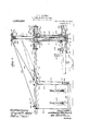
- Figure 1 is a side elevation and part sectional view of substan- 49 having a block 10 fixed thereon.
- FIG. 2 is a ⁇ general plan view showing only suliicicnt ot' the device. to make clear the features of the present invention
- Fig. 3 is a detail plan view on an cnlarged scale of a head section:
- Fig. #lY is a dcvelopment in side view showing the platform, its suspension means. the Yanimal tigures to be ridden and their operating devices;
- Fig. 5 is a plan view of one of the platform sections; Fig'.
- t3 showszthe manner of detachably connecting tht ⁇ platform scctions to their supporting means to form the complete platform
- Fig. 7 is a detail in side elevation showing ⁇ the animal figure supports and rock shaft
- Fig. 8 is an ein lai-ged detail looking in the direction of the arrow, Fig. l, and showing the end of one of the supporting bars. the detachable and locking hook connection between said bars ⁇ the brace or tie rods. and platform suspending links, and also the spacing bars between the suspension bars.
- the device as a whole is preferably carried upon a suitable truck, such as A. Figs. l and Q, which may be of a size and character to give steady and stable support to the operating parts when in use. and afford a means for transportingthe tower and main portions of the device and associated ymechanism.
- a suitable truck such as A. Figs. l and Q, which may be of a size and character to give steady and stable support to the operating parts when in use. and afford a means for transportingthe tower and main portions of the device and associated ymechanism.
- the truck A is shown as having a suit ⁇ able body or frame formed of the longitw dinal pieces 1 and cross-pieces Q carried upon wheels 3 and having a steering device 4, whereby under the action of suitable motive power, not necessary to illustrate. the truck and parts carried may be moved from place to place.
- Fig. 2. that the center cross-pieces 2, 2 sustain the metal pieces 5.
- Fig. l preferably of beam form which serve as a support for-the tower and its adjacent parts, presently to be described.
- the tower base 6 Secured to the beams 5, 5, is the tower base 6 from which rises the tower lower tube 7 fiXedly secured t0 the base cap.
- a fixed guide collar or sleeve 8 At the upper portion of the tube 7 and within the same is a fixed guide collar or sleeve 8 through which extends the tower upper tube
- the tower tubes 7 and 9 are non-rotative and the upper one is arranged to telescope with relation to the lower one for a purpose that will presently a pear.
- the block 10 is preferably provided with a threaded perforation to receive the exteriorly threaded tower adjusting rod 11, and the two tubes 7 and 9 are held from relative rotatable movement by means of a key-way 12 in the lower tube 7 which may be engaged by a suitable key or pin 13 projecting from the upper tube 9.
- the tower adjusting rod 11 is provided with meanswhereby it may be rotated ,to thereby cause relative telescopic movement of the upper and lower tower tubes.
- the lower portion of the rod 11 is provided with a, lixed collar or head 14 which rests upon the upper surface of the base cap 6, and has an extension 15, which passes through the base cap, and has secured thereto a bevel gear 16, Fig. l, adapted to engage a bevel gear 17 carried by a shaft 18 mounted on the truck frame.
- the shaft 18 may be provided with a sprocket wheel 19, Fi 1, whereby power may be transmitted t rough the means described to rotate the tower adjusting screw 11.
- the means described for rotating the tower adjusting screw may be conveniently formed as stated, or it may be modified, the essentials in this respect being that there be provided suitable operating devices for turning the tower adJusting screw 11 to thereby relatively move the tower tubes 7 and 9 longitudinally.
- This case 20 is preferably supported by anti-friction bearings, and as one form thereof the base cap 6 vsustains and has secured to it a flanged collar 21, Fig. 1, whicha'ords a suitable race-way for a series of conical rolls O22 which travel on the upper surface of the collar ange and support the Icase'a'nd Aa further race-way for a series of cylindrical rolls 23 which maintain the lower portion of the case in proper position horizontally.
- roller oranti-friction devices for sustaining the case 20 mav he variously'formed within the true sco e of the Yresent invention or if desired other forms of bearings for the lower end of the case 20 ymay be employed, the essentials in this respect being that the case 20may be properly held by suitable bearings at its lower emi to rotate with substantial accuracy about the axis of the tower' vided with a cap sleeve 24 having a flange 25 for sustaining a series of anti-friction rolls or balls 26 against whichthe inner surface of the enlarged'part 27 of the case 2O bears.
- the case 20 is rotatably supported at both its lower and upper portions by anti-friction devices in ⁇ order that it may be rotated with ease, but it is to be understood that the manner of supporting the case may be varied, the essentials in this respect being that itbe sustained rotatably about the tower lower tube.
- the rotatable case 2O is provided with means for rotating it, and as illustrated this means may conveniently comprise a gear 28 secured to the lower part of the rotatable case 20 and adapted to engage a gear 29,
- the capstan or case head for carrying the inner ends of the supporting bars 31, Figs. 1 and 2.
- This head is preferably formed of several sections for simplicity of manufacture and assembling, ⁇ each section comprising a base flange 32 to fit vupon and be secured to the enlarged upper part 27 of the rotatable case, an upper plate 33, Figs/1 and 3, end rests 34 forl the inner ends of supporting arms 31, and a web 35 in the form of a bracket.
- Each section is preferably formed of several sections for simplicity of manufacture and assembling, ⁇ each section comprising a base flange 32 to fit vupon and be secured to the enlarged upper part 27 of the rotatable case, an upper plate 33, Figs/1 and 3, end rests 34 forl the inner ends of supporting arms 31, and a web 35 in the form of a bracket.
- capstan head is preferably adapted to support the inner ends of three supporting bars 31, but, of course, this number may be varied, and regardless of the number thus supportedwhen these sections are assembled and secured to the case 20, they form a complete circle 0f supports for as many supporting arms 31 as desired.
- Such additional means in the present invention comprises tie or 'brace rods extending from the tower upper' tube, and detachable connections between these tie or brace rods and supporting-bars, and between the vplatform suspending means and4 supporting bars, said detachable connections being such that when the parts are in operative position, as indicated by full lines in Fig. 1, these detachable connections are locked, as will hereinafter appear, and the platform suspending means cannot become detached.
- a cap 36 Secured to the upper portion of the tower upper tube 9 is a cap 36 having a race-way 37 for a series of anti-friction'rolls 38 on which,resttlie rotatingsupport 39 to which the upper ends of the tie or brace rods 40, 41 are secured,"fit" being understood, of course, thateach supporting bar 31 has its outer portion sustained by a pair of said tie rodsv as indicated in Fig. 1.
- the rotating support 39 for the ends of the tierods may be rotatably supported by the cap 36 or tower upper tube in any suit-- able manner, but a preferred form ofconstruction is indicated by Fig. 1, wherein the cap 36 has a sleeve portion 42 extending into t-he tower upper tube 9, Fig. 1, and the rotating support 39 has a part 43 extending through the sleeve portion 42 and provided with an enlarged head 44, whereby, the support 39 may freelyrotate and yet be held in operative position with respect to the cap 36.
- a hook 45, Figs. 1 and 8 formed as part of or secured to a plate 46 which is attached to the supporting arm by suitable bolts 47 and 48.
- the tierod 41 foreach arm is provided with a loop 52 similar to the loop 50 jointed to the tie rod and adapted to pass over Vthe end of the supporting arms.
- the hooks 45 and 51 on each supporting arm are separated a distance to accommodate them for engagement with the platform suspending means, which comprise a series of platform suspending rods 53 each having an upper link 54 adapted to engage one of thehooks 45 or 51, Figs. 1 and 8. It is desirable to revent accidental disengagement o-f the links 54 fromA the suspension hooks while the apparatus is in use and to do this effectively without special and complicated locking means and at the same time to'permit ready and quick disengagement, the presentl invention contemplates making the entrance opening 55 of the hooks of a size that will ermit the passage ,singly of the loops or inks and when the loops and links Iare engaged with said hooks that the engaged part 56, Fig.
- the present invention contemplates providing the lower end of the supporting .rods 53 each with an elongated eye- 57 which may either be formed integral with the supporting rods or properly securedl thereto, as indicated in Fig. 6.
- the platform for supporting the figures comprises a series of sections 58, Fig. 5, each of which has a floor supporting beam 59 at itsinner and outer portion to which beams are secured, as indicated by Fig. 6, the platform hooks 60.
- These platform hooks 60 are so arranged that their hooked ends 61 may pass into the opening 62 of the elongated eye 57 and engage the lower cross bar v63 of said elongated eye, substantially as indicated in Fig. 6. From this construction it will be seen that t-he platform sections 58 may be readily and easily detached from the supporting rods 53, and while thc present invention contemplates the elongated eyes 57 for sustaining the plat-form sections from the supporting bars, it is obvious that the construction may be modified.
- rock shafts 64 Mounted upon suitable supports, preferably below the top surface of the platform sections 58 are the rock shafts 64, see Figs. 5 and 7.
- Each of these rock shafts carries appropriate socket pieces 65- froml which rise the figure supporting arms 66.
- These socket pieces 65 are preferably formed of a shape to permit the supporting arms 66 to be readily disengaged therefrom, and as one form of means to this end they are made conical, as indicated in Fig. 7, the conical socketof each part 65 being adapted to receive the conical end portion of the ligure supporting arm 66.
- the figures which may be that of an animal or some other appropriatel character such as represented in'F ig. 4, and indicated as 67, are preferably pivoted at 68 and 69 to the upper end portions of the ligure Isupporting arms 66.
- crank arm T0 Secured to one of the rock shafts 64 as supporting bars indicated by Figs. 4 and 5. is a crank arm T0 to which is connected at. 7l a figure operating arm TQ jointed at its upper end to a bell crank T3 pivoted at T-t to one ot the 3l. as indicated in Fig. 1.
- link T5 To the upper end of the bell crank 73 is connected a link T5, the inner end of which is joined to a pivoted arm 7G, Figs. 2 and 3,
- the rock shafts 64 'of the adjoining sections may be joined by the rods 8l connected to arms 82 secured to theV adjacent rock shafts, the construction being such that upon operation of one figure by its operating means suoli as described, the figure on the adjoining section or sections may be properly moved.
- the capstan head for supporting the supporting bars 3l is preferably formed in sections, as indicated'in Figs. 2 and 3, each section providing a series of three-end -rests 3st for the supporting bars.
- the number of end rests thus provided by each portion of the divisible capstan head may vary, but they are preferably less than the total number of supporting bars so that the device may be readily disassembled and put together.
- the present invention contemplates the end spacing rods 83, see Figs. 2 and 8, each of which has a flattened end portion 84.- to engage about a washer or collar 85 held upon the through-b0lt-48 which may preferably also be the bolt for holding the hooks 4:5 and 5l to the supporting bars, all as indicated by Fig. 8. It is preferable also that the washer 85 be of a size substantially the same as the head S6 of the bolt 4S, whereby the ends of the spacin'g rods may be readily and quickly eiigaged with and disengaged from said bolt.
- the spacing rods S3 may be duplicated one at the outer ends of the supporting bars and the other at points intermediate the outer and innereiids, as indicated by j ino' non-rotatable sections, a rotatable case or, column surrounding a Part of the tower and having end rests, supporting arms having their inner ends resting on said end rests, tie rods connecting the upper portion vof the telescopic tower with said supporting arms and holding the inner ends of said arms on said rests, and ymeans for telescoping the tower sections to lowerthe outer ends of the supporting arms and permit the inner ends 'thereof to be drawn from the end rests of the case or column.
- a tower comprising telescoping non-rotatable tubular sections, means for telescoping the sections, a rotatable casing surrounding the telescoping tower, supporting arms carried-by the casing, tie rods having connection with the supporting arms and permitting ready detachment therefrom when the tower'is in contracted condition.
- a/truck In ay carousel or merry-go-round, the combination of a/truck, a telescoping tower and rotatable case carried by said truck, means for telescoping the tower and rotating said case., supporting arms extending outward from the rotatable case, tie rods connecting the said arms with the upper part of the telescoping tower, and means joining said tierods to said arms to permit ready detachment when the tower is lowered. 5.
- a truck In a carousel or merry-go-round, a truck, a tower formed of telescoping sections supportedpby said trucka rotatable case surrounding the lower portion kofthe tower 'and carrying supporting ⁇ arms, a screw device for telescoping the tower sections, and means for turning the screw.
- VT In a device of the character described, the combination of a telescoping tower and rotatable case,;ys upporting arms extending outward fro1i'r ⁇ said case.
- tie rods connected to the upper portion of the telescoping tower and having loop end portions to engage over the ends of the supporting bars,'and means for telescoping the tower to slacken the tie rods and permit the loop end portions to be disengaged from the ends of the supporting arms.
- a. telescoping tower and rotatable case supporting arms extending outward from said case and having hooks, platform supports having links engaging said hooks, tie rods connected to the tower and having loops to also engage said hooks, and means for lowering the tower telescopingly to permit the tie rod loops to be disengaged from said hooks.
- a telescoping tower and rotatable case supporting arms extending outward from said .case and having hooks, said hooks being disposed at the under side of said supporting arms with their opening facing outward, platform supports having links engagingy said hooks, tie rods connect-ed to the tower and having loops to also engagey said hooks, and means for lowering' the tower telescopingly to permit-the tie rod loops to be disengaged from said hooks.
- a tower formed of telescoping sections and a rotatable case, supporting arms extendingfrom said case, and having hooks
- 'platform supports having links for engaging said hooks, ⁇ tie rods connected to the tower and having loops for also engaging said hooks above the said links andlocking thesaid links from disengagement from the hooks, and means for telescoping the tower to permit the tie loops and platform supporting links to be disengaged from said hooks.
- a truck a tower formed of telescoping non-rotatable lsections and mounted on said truck, a rotatable case surrounding thelower section of the tower, and having a capstan head provided with end rests, supporting arms having vtheir inner ends rest-ing on said' end rests, a rotatable cap carried by the upper section of the tower, tie rods having one end secured to/ the rotatable cap and provided at the other with a loop to pass about the end of a supporting bar, and means for telescoping the telescopic section of the tower, tie rods connecting said rotatable cap and supporting arms, and means within the tubular sections of the tower for telescoping said tower sections.
- a tower formed of telescopic sections, supporting bars extending radially therefron, platform supporting rods connected to said bars and having elongated eyes at their lower ends, a platform formed of sections having open hooks for engaging with said elongated eyes.
Description
W. C. FARNUM.
CAROUSEL 0R MERRY-Go-ROUND.
APPLICATION FILED APR.3, 1913.
Patented Feb. 24, 1914.
W. C. FARNUM.
OAROUSEL 0R MBRRY-GO-EOUND.
APPLICATION FILED Amm. 1913.
1,088,558. Patented Feb. 24, 1914.
3 SHEETS-SHEET 2.
l *JL W. C. FARN UM.
GAROUSEL 0R MERRY-Go-ROUND.
APPLICATION FILED APB..3, 1913y 1,088,558., Patented Feb.24,1914
3 SHEETS-SHEET 3.
' UNITED STATES OFFICE.
WILLIAM C; FARNUM, OF WINCHENDON, MASSACHUSETTS. ASSIGNOR TO HIMSELF, AND WILLIAM F. PARMELEE AND WETMORE W. STEVES, BOTH OF FITCHBURG,
MASSACHUSETTS.
Specification of Letters Patent.
CAROUSEL 0R MERRY-GO-ROUND.
Patented Feb. 24, 1914.
To all ur/0m it may concern:
Be it known that I, XVHQIJAM C. FARNUM, a citizen of the United States, residing in `Winehendon, county of Torcesteig and State of Massachusetts, have invented an Improvement in Carousels or Merry-Gofltounds, of which the following description, in connection with the accompanying drawings, is a specification` like letters on the drawings representing like parts.
The invention to be hereinafter described relates to an'iusement devices or apparat-us and more especially to the type known as carousels or merry-go-rounds. Devices of this character are intended to be set up and used for a time in one location and then removed to another, according to the dictates of circumstances. It is important, therefore, that the parts thereof be so associated and connected thatI they may be readily disassociated and reassembled, and that this change of relationship of the parts may be effected quickly and with minilnuln expense incident to the employment of operatives. It is further desir-able that while a device of this character shall possess these ycharacteristics which dictate simplicity of construction, it shall also possess the attractions incident tov the use of rocking animal tigures on which persons may ride, and further that it be driven by means of power through ,suitable transmitting mechanism. 'l`hese'various features, either alone or in combination, make the problem of ready and economical transportation one of ditli! cult solution, as will be readily understood, and dictate that when the parts are assembled for use they shall be so united that perfect safety may be insured and yet that by simple and easily handled means they may be readily taken apart and put together.
lVith the above generally stated facts in mind, the aims andy purposes of the invention will best be made clear by the following description and accompanying drawings of'one form of means for carrying the invention into practical effect, it being understood, of course, that the invention is not necessarily limited to the particulars of the means shown and described. but embraces various changes thatl are within the true scope of the actual invention as definitely set forth by the claims.
In the drawings Figure 1 is a side elevation and part sectional view of substan- 49 having a block 10 fixed thereon.
tially one half portion of a carousel or merry-gQ-round embracingr features ot' the present invention; Fig. 2 is a `general plan view showing only suliicicnt ot' the device. to make clear the features of the present invention; Fig. 3 is a detail plan view on an cnlarged scale of a head section: Fig. #lY is a dcvelopment in side view showing the platform, its suspension means. the Yanimal tigures to be ridden and their operating devices; Fig. 5 is a plan view of one of the platform sections; Fig'. t3 showszthe manner of detachably connecting tht` platform scctions to their supporting means to form the complete platform; Fig. 7 is a detail in side elevation showing` the animal figure supports and rock shaft: and Fig. 8 is an ein lai-ged detail looking in the direction of the arrow, Fig. l, and showing the end of one of the supporting bars. the detachable and locking hook connection between said bars` the brace or tie rods. and platform suspending links, and also the spacing bars between the suspension bars. l
The device as a whole is preferably carried upon a suitable truck, such as A. Figs. l and Q, which may be of a size and character to give steady and stable support to the operating parts when in use. and afford a means for transportingthe tower and main portions of the device and associated ymechanism. In the present form of the invention the truck A is shown as having a suit` able body or frame formed of the longitw dinal pieces 1 and cross-pieces Q carried upon wheels 3 and having a steering device 4, whereby under the action of suitable motive power, not necessary to illustrate. the truck and parts carried may be moved from place to place.
It will be noted, Fig. 2. that the center cross-pieces 2, 2 sustain the metal pieces 5. i5, Fig. l, preferably of beam form which serve as a support for-the tower and its adjacent parts, presently to be described.
Secured to the beams 5, 5, is the tower base 6 from which rises the tower lower tube 7 fiXedly secured t0 the base cap. At the upper portion of the tube 7 and within the same is a fixed guide collar or sleeve 8 through which extends the tower upper tube The tower tubes 7 and 9 are non-rotative and the upper one is arranged to telescope with relation to the lower one for a purpose that will presently a pear. To effect this telescopic relation o the tower tube in the form of the invention illustrated, the block 10 is preferably provided with a threaded perforation to receive the exteriorly threaded tower adjusting rod 11, and the two tubes 7 and 9 are held from relative rotatable movement by means of a key-way 12 in the lower tube 7 which may be engaged by a suitable key or pin 13 projecting from the upper tube 9.
lThe tower adjusting rod 11 is provided with meanswhereby it may be rotated ,to thereby cause relative telescopic movement of the upper and lower tower tubes. As one means to this end the lower portion of the rod 11 is provided with a, lixed collar or head 14 which rests upon the upper surface of the base cap 6, and has an extension 15, which passes through the base cap, and has secured thereto a bevel gear 16, Fig. l, adapted to engage a bevel gear 17 carried by a shaft 18 mounted on the truck frame. The shaft 18 may be provided with a sprocket wheel 19, Fi 1, whereby power may be transmitted t rough the means described to rotate the tower adjusting screw 11. The means described for rotating the tower adjusting screw may be conveniently formed as stated, or it may be modified, the essentials in this respect being that there be provided suitable operating devices for turning the tower adJusting screw 11 to thereby relatively move the tower tubes 7 and 9 longitudinally.
Surrounding the tower lower tube 7 is the column or rotatable case 29, Fig. 1,which carries and gives rotary movement to the supporting bars which sustain the animal or other figures. This case 20 is preferably supported by anti-friction bearings, and as one form thereof the base cap 6 vsustains and has secured to it a flanged collar 21, Fig. 1, whicha'ords a suitable race-way for a series of conical rolls O22 which travel on the upper surface of the collar ange and support the Icase'a'nd Aa further race-way for a series of cylindrical rolls 23 which maintain the lower portion of the case in proper position horizontally. Obviously the roller oranti-friction devices for sustaining the case 20 mav he variously'formed within the true sco e of the Yresent invention or if desired other forms of bearings for the lower end of the case 20 ymay be employed, the essentials in this respect being that the case 20may be properly held by suitable bearings at its lower emi to rotate with substantial accuracy about the axis of the tower' vided with a cap sleeve 24 having a flange 25 for sustaining a series of anti-friction rolls or balls 26 against whichthe inner surface of the enlarged'part 27 of the case 2O bears. Thus the case 20 is rotatably supported at both its lower and upper portions by anti-friction devices in `order that it may be rotated with ease, but it is to be understood that the manner of supporting the case may be varied, the essentials in this respect being that itbe sustained rotatably about the tower lower tube.
The rotatable case 2O is provided with means for rotating it, and as illustrated this means may conveniently comprise a gear 28 secured to the lower part of the rotatable case 20 and adapted to engage a gear 29,
suitable source of power through the pulley 30. lt will be obvious that otheLforms of means may be employed to rotate the case 20, although that described is agood and convenient mechanism and is carried by the truck.
Mounted upon the upper portion of the rotatable case or column 20 is the capstan or case head for carrying the inner ends of the supporting bars 31, Figs. 1 and 2. This head is preferably formed of several sections for simplicity of manufacture and assembling, `each section comprising a base flange 32 to fit vupon and be secured to the enlarged upper part 27 of the rotatable case, an upper plate 33, Figs/1 and 3, end rests 34 forl the inner ends of supporting arms 31, and a web 35 in the form of a bracket. Each section. of the capstan head is preferably adapted to support the inner ends of three supporting bars 31, but, of course, this number may be varied, and regardless of the number thus supportedwhen these sections are assembled and secured to the case 20, they form a complete circle 0f supports for as many supporting arms 31 as desired.
It will be noted upon reference to Fig. 1 that the -inner ends of the supporting arms 31 simply rest upon the end rests 34 of the head sections and that the outer ends of said -arms would fall if means werenot provided in addition to the end rests 34. Such additional means in the present invention comprises tie or 'brace rods extending from the tower upper' tube, and detachable connections between these tie or brace rods and supporting-bars, and between the vplatform suspending means and4 supporting bars, said detachable connections being such that when the parts are in operative position, as indicated by full lines in Fig. 1, these detachable connections are locked, as will hereinafter appear, and the platform suspending means cannot become detached. but when' the tower upper tube is lowered, as indicated by dotted lines, Fig. 1, the plat-form suspending means Figs. 1 and 2, which may be driven fromvany as well as the tie or brace iods may be readily and conveniently detached, as will presently appear. l
Secured to the upper portion of the tower upper tube 9 is a cap 36 having a race-way 37 for a series of anti-friction'rolls 38 on which,resttlie rotatingsupport 39 to which the upper ends of the tie or brace rods 40, 41 are secured,"fit" being understood, of course, thateach supporting bar 31 has its outer portion sustained by a pair of said tie rodsv as indicated in Fig. 1.
The rotating support 39 for the ends of the tierods may be rotatably supported by the cap 36 or tower upper tube in any suit-- able manner, but a preferred form ofconstruction is indicated by Fig. 1, wherein the cap 36 has a sleeve portion 42 extending into t-he tower upper tube 9, Fig. 1, and the rotating support 39 has a part 43 extending through the sleeve portion 42 and provided with an enlarged head 44, whereby, the support 39 may freelyrotate and yet be held in operative position with respect to the cap 36. Secured to the outer end of ea'cli supporting arm 31 is a hook 45, Figs. 1 and 8, formed as part of or secured to a plate 46 which is attached to the supporting arm by suitable bolts 47 and 48. JointedY tol the tie rod 40 at 49 isa loop 50 adapted to readily pass over the end of the supporting arm 31 and engage the hook 45. Similarly at a point between the ends of each supporting bar is the hook 51, which ma be as to all material construction substantially the same as the hook 45. The tierod 41 foreach arm is provided with a loop 52 similar to the loop 50 jointed to the tie rod and adapted to pass over Vthe end of the supporting arms.
The hooks 45 and 51 on each supporting arm are separated a distance to accommodate them for engagement with the platform suspending means, which comprise a series of platform suspending rods 53 each having an upper link 54 adapted to engage one of thehooks 45 or 51, Figs. 1 and 8. It is desirable to revent accidental disengagement o-f the links 54 fromA the suspension hooks while the apparatus is in use and to do this effectively without special and complicated locking means and at the same time to'permit ready and quick disengagement, the presentl invention contemplates making the entrance opening 55 of the hooks of a size that will ermit the passage ,singly of the loops or inks and when the loops and links Iare engaged with said hooks that the engaged part 56, Fig. 8, of a loop will be substantially in vertical position over the engaged part of the link, the construction being such that when the parts are engaged as stated, the links arelocked by the loops from becomin disengaged from the hooks. To effect the isengagement, the upper tube 9 is 'lowered by the means already described, thus permitting the supporting bars 31 to be loweredinto. dotted line position, Fig. 1, and the plat-form B to restupon the ground, whereupon the tie rod loops may be disengaged from the hooks and thereafter the links of the platform suspending rods may be readily disengaged.
From the construction hei'einbefore described, it will vbe apparent that the inner ends of the supporting bars 31 rest upon the end rests 34 and when the tie rods 40 and 41 are taut by raising the telescopiiig tower, these supporting arms have their outer ends raised to the full line position and their inner ends held upon the end rests.
In a device of this character, ready transportation and economy of assembling and disassembling require that the plat-form on which the figures are mounted shall be readily detachable from its supports, such as 53. To this end the present invention contemplates providing the lower end of the supporting .rods 53 each with an elongated eye- 57 which may either be formed integral with the supporting rods or properly securedl thereto, as indicated in Fig. 6.
The platform for supporting the figures comprises a series of sections 58, Fig. 5, each of which has a floor supporting beam 59 at itsinner and outer portion to which beams are secured, as indicated by Fig. 6, the platform hooks 60. These platform hooks 60 are so arranged that their hooked ends 61 may pass into the opening 62 of the elongated eye 57 and engage the lower cross bar v63 of said elongated eye, substantially as indicated in Fig. 6. From this construction it will be seen that t-he platform sections 58 may be readily and easily detached from the supporting rods 53, and while thc present invention contemplates the elongated eyes 57 for sustaining the plat-form sections from the supporting bars, it is obvious that the construction may be modified.
Mounted upon suitable supports, preferably below the top surface of the platform sections 58 are the rock shafts 64, see Figs. 5 and 7. Each of these rock shafts carries appropriate socket pieces 65- froml which rise the figure supporting arms 66. These socket pieces 65, are preferably formed of a shape to permit the supporting arms 66 to be readily disengaged therefrom, and as one form of means to this end they are made conical, as indicated in Fig. 7, the conical socketof each part 65 being adapted to receive the conical end portion of the ligure supporting arm 66.
The figures which may be that of an animal or some other appropriatel character such as represented in'F ig. 4, and indicated as 67, are preferably pivoted at 68 and 69 to the upper end portions of the ligure Isupporting arms 66.
Secured to one of the rock shafts 64 as supporting bars indicated by Figs. 4 and 5. is a crank arm T0 to which is connected at. 7l a figure operating arm TQ jointed at its upper end to a bell crank T3 pivoted at T-t to one ot the 3l. as indicated in Fig. 1. To the upper end of the bell crank 73 is connected a link T5, the inner end of which is joined to a pivoted arm 7G, Figs. 2 and 3,
which is itself pivoted at 77 to one of the sections of the capstan head or other suitable support adjacent the top part ofthe rotating case 20';
In order to properly move the igures or impart to them a rocking movement as the platform is carried around bv the supporting bars, there is secured to the top portion of the stationary tube 7, Fig. l,`a cam member 78 having a cam-like groove 79 around its outer periphery, `substantially as indicated in Figs.y l and 2, 'which cam'is engaged by a suitable roller 80 projecting upwaril from the pivoted arin76 as indicated in Fig. l, the construction being suoli that as the case 2O and the supporting bars with the suspended platform rotate, the arms 76 by .engagement of the rollers 80 withy they stationary cam 79 will impart to the links 7 5 and perforce to the rock shaft 6-1, a rock ing movement, therebygivingto the figures on the platform the desired-motion.
In order that the figures may be properly moved on the adjacent platform sections without thenecessity of multiplication of the figure-operating means, the rock shafts 64 'of the adjoining sections may be joined by the rods 8l connected to arms 82 secured to theV adjacent rock shafts, the construction being such that upon operation of one figure by its operating means suoli as described, the figure on the adjoining section or sections may be properly moved.
In the present form of the invention, where it is desirable to disassemble the parts quickly, the capstan head for supporting the supporting bars 3l is preferably formed in sections, as indicated'in Figs. 2 and 3, each section providing a series of three-end -rests 3st for the supporting bars. Of course the number of end rests thus provided by each portion of the divisible capstan head may vary, but they are preferably less than the total number of supporting bars so that the device may be readily disassembled and put together.
'It is desirable that the outer ends of the supporting bars 31 be properly spaced apart and tol this end the present invention contemplates the end spacing rods 83, see Figs. 2 and 8, each of which has a flattened end portion 84.- to engage about a washer or collar 85 held upon the through-b0lt-48 which may preferably also be the bolt for holding the hooks 4:5 and 5l to the supporting bars, all as indicated by Fig. 8. It is preferable also that the washer 85 be of a size substantially the same as the head S6 of the bolt 4S, whereby the ends of the spacin'g rods may be readily and quickly eiigaged with and disengaged from said bolt. Obviously the spacing rods S3 may be duplicated one at the outer ends of the supporting bars and the other at points intermediate the outer and innereiids, as indicated by j ino' non-rotatable sections, a rotatable case or, column surrounding a Part of the tower and having end rests, supporting arms having their inner ends resting on said end rests, tie rods connecting the upper portion vof the telescopic tower with said supporting arms and holding the inner ends of said arms on said rests, and ymeans for telescoping the tower sections to lowerthe outer ends of the supporting arms and permit the inner ends 'thereof to be drawn from the end rests of the case or column.
3. In a carousel or merry-go-round, the
combination of a tower comprising telescoping non-rotatable tubular sections, means for telescoping the sections, a rotatable casing surrounding the telescoping tower, supporting arms carried-by the casing, tie rods having connection with the supporting arms and permitting ready detachment therefrom when the tower'is in contracted condition.
4. In ay carousel or merry-go-round, the combination of a/truck, a telescoping tower and rotatable case carried by said truck, means for telescoping the tower and rotating said case., supporting arms extending outward from the rotatable case, tie rods connecting the said arms with the upper part of the telescoping tower, and means joining said tierods to said arms to permit ready detachment when the tower is lowered. 5. In a carousel or merry-go-round, a truck, a tower formed of telescoping sections supportedpby said trucka rotatable case surrounding the lower portion kofthe tower 'and carrying supporting` arms, a screw device for telescoping the tower sections, and means for turning the screw.
6. In a carousel or merry-go-round, the combination of a truck, a tower formed of 2. In a carousel or ymerry-go-round, theconibination of a tower formed of telescoptelescoping tubular sections supported by said truck, a rotatable case surrounding the lower part of the tower, a threaded rod eX- tending inside the tubular tower sections for telescoping said sections, and means for' operating the screw.
VT. In a device of the character described, the combination of a telescoping tower and rotatable case,;ys upporting arms extending outward fro1i'r`said case. tie rods connected to the upper portion of the telescoping tower and having loop end portions to engage over the ends of the supporting bars,'and means for telescoping the tower to slacken the tie rods and permit the loop end portions to be disengaged from the ends of the supporting arms.
8. In a carousel or merrv-go-round, the combination of a. telescoping tower and rotatable case, supporting arms extending outward from said case and having hooks, platform supports having links engaging said hooks, tie rods connected to the tower and having loops to also engage said hooks, and means for lowering the tower telescopingly to permit the tie rod loops to be disengaged from said hooks.
9. In a .carousel or merry-go-round, the combination of a telescoping tower and rotatable case, supporting arms extending outward from said .case and having hooks, said hooks being disposed at the under side of said supporting arms with their opening facing outward, platform supports having links engagingy said hooks, tie rods connect-ed to the tower and having loops to also engagey said hooks, and means for lowering' the tower telescopingly to permit-the tie rod loops to be disengaged from said hooks.
10. In a carousel or merry-go-round, the combination of a tower formed of telescoping sections and a rotatable case, supporting arms extendingfrom said case, and having hooks, 'platform supports having links for engaging said hooks,` tie rods connected to the tower and having loops for also engaging said hooks above the said links andlocking thesaid links from disengagement from the hooks, and means for telescoping the tower to permit the tie loops and platform supporting links to be disengaged from said hooks.
11. In a carousel or merry-go-round, the. combination of a truck, a tower formed of telescoping non-rotatable lsections and mounted on said truck, a rotatable case surrounding thelower section of the tower, and having a capstan head provided with end rests, supporting arms having vtheir inner ends rest-ing on said' end rests, a rotatable cap carried by the upper section of the tower, tie rods having one end secured to/ the rotatable cap and provided at the other with a loop to pass about the end of a supporting bar, and means for telescoping the telescopic section of the tower, tie rods connecting said rotatable cap and supporting arms, and means within the tubular sections of the tower for telescoping said tower sections.
13. In a carousel or merry-go-round, the combination of a truck, a tower formed of non-rotatable telescopic sections mounted on said truck, a rotating cap mounted upon the top portion of the upper telescopic section, supporting bars and a rotatable case surrounding the lower telescopic section having end rests for said bars, tie rods connecting the supporting bars with the rotatable cap, and means for raising and lowering the upper telescopic section.
14. In a carousel or merry-go-round, the
combinationof a truck, a tower formed ofv non-rotatable telescopic sections, a rotating case surrounding the lower of said sections and having a capstan head, supporting bars extending from said head, figures supported by said bars, a cam secured to the non-1o tatable vtelescopic sections, and means connecting said cam with said figures to impart motion thereto.
15. In a carousel or merry-go-round, the combination of a truck, a tower formed of non-rotatable telescopic sections and lpermanentl7 mounted on said truck, a rotating case surrounding the lower member of the telescopic sections and having a series of supporting bars extending therefrom, a screw extending axially of the telescopic sections and having a gear connected thereto, and means for operating the said gear to turn the screw to cause the sections to be relatively moved telescopically.
16. In a carousel or merry-go-round, the combination of a truck, a base cap secured to said truck, a non-rotatable tubular sect-ion secured to and rising from said base cap, an upper tubular section telescopically connected to said first-named section, a rotating case, arms projecting therefrom, and tie rods connecting said upper section with the said supporting bars.
17. In a carousel or merry-go-round, the
combination of a tower formed of telescopic sections, a truck on which said tower is permanentb7 secured, a rotating case having supporting bars projecting therefrom, tie rods connecting the telescopic tower with the supporting bars, a platform and means for suspending it from the supporting bars,
and detachable means for connectin the sections ofthe platform end to end an with the platform suspending means.
18. In a carousel or merry-goaround, the combination of a tower formed of telescopic sections, supporting bars extending radially therefron, platform supporting rods connected to said bars and having elongated eyes at their lower ends, a platform formed of sections having open hooks for engaging with said elongated eyes.
19. In a carousel or merry-go-round, the combination of a tower formed of telescopic sections, a truck to which said telescopic tower is permanently connected, supporting arms extending radially from the tower and a platform supported `from said arms, rock shafts carried by .the platform and having socket pieces secured thereto, jfigure supporting `rods having ends for detachably lengaga` ing said socket pieces, and means for ing the rock shaft., v
20. In a carousel or merry-go-round, the combination of a tower formed of telescopic rock'- sections, supporting bars extending radially from said tower, tie rods connecting the' supv portingbarswith the upper member of .the telescopic tower, a platform suspended from said supporting bars and formed of sections, gures mounted on the platform,
means carried by the supporting bars Iforl rocking one of said figures, and vconnections between the adjacent figures whereby movementof one is imparted to the other.
21. In a carousel or merry-go-round, the combination of a tower formed of telescopic sections, supporting bars extending radially therefrom, tie rods connecting the-bars with the upper member of the telescopic tower,
22. In a carousel or merry-go-round, the
combination of a tower formed of telescopic 'tubular sections, a rotating case surrounding the lower section and having' a capstan head provided with end rests 34, supporting bars 31 projecting from the end rests, tie rods connecting the supporting bars with the upper'member of the telescopic tower, means connecting the upper and lower sections of the telescopic tower permittingV them to move relatively in a longitudinal direction and maintaining them from relative rotation, and means for telescoping the tower sections.
23. In a carousel or merry-go-round, the combination of a. truck, a telescopictower permanently secured to the truck and rising therefrom, a rotatable cap surrounding the upper section of the telescopic tower, a case having a capstan head provided with end rests 34, supporting bars having their inner ends engaged by said rests,- and tie rods connecting the rotatable cap with said supporting bars, and means for telescoping the sections with respectto each other.
In testimony whereof, I have signed my name to this specification, in the presence of two subscribing witnesses.
WILLIAM C. FARNUM. Witnesses:
FRANK B. SPALTER, ELLIOT S. TUCKER.
Priority Applications (1)
| Application Number | Priority Date | Filing Date | Title |
|---|---|---|---|
| US75858913A US1088558A (en) | 1913-04-03 | 1913-04-03 | Carousel or merry-go-round. |
Applications Claiming Priority (1)
| Application Number | Priority Date | Filing Date | Title |
|---|---|---|---|
| US75858913A US1088558A (en) | 1913-04-03 | 1913-04-03 | Carousel or merry-go-round. |
Publications (1)
| Publication Number | Publication Date |
|---|---|
| US1088558A true US1088558A (en) | 1914-02-24 |
Family
ID=3156782
Family Applications (1)
| Application Number | Title | Priority Date | Filing Date |
|---|---|---|---|
| US75858913A Expired - Lifetime US1088558A (en) | 1913-04-03 | 1913-04-03 | Carousel or merry-go-round. |
Country Status (1)
| Country | Link |
|---|---|
| US (1) | US1088558A (en) |
Cited By (1)
| Publication number | Priority date | Publication date | Assignee | Title |
|---|---|---|---|---|
| US5303603A (en) * | 1992-12-17 | 1994-04-19 | Boots David A | Method for imparting cyclic vertical motion to carousel animals |
-
1913
- 1913-04-03 US US75858913A patent/US1088558A/en not_active Expired - Lifetime
Cited By (1)
| Publication number | Priority date | Publication date | Assignee | Title |
|---|---|---|---|---|
| US5303603A (en) * | 1992-12-17 | 1994-04-19 | Boots David A | Method for imparting cyclic vertical motion to carousel animals |
Similar Documents
| Publication | Publication Date | Title |
|---|---|---|
| US2468893A (en) | Airplane amusement device | |
| US2847216A (en) | Amusement ride apparatus | |
| US973105A (en) | Amusement apparatus. | |
| US1088558A (en) | Carousel or merry-go-round. | |
| US1082177A (en) | Apparatus for handling invalids or the like. | |
| US2934341A (en) | Passenger amusement ride | |
| US1101217A (en) | Burial apparatus. | |
| US3226113A (en) | Collapsible wheel structure for rotary amusement devices | |
| US1799409A (en) | Amusement apparatus | |
| CN107472427A (en) | A kind of Height Adjustable toy for children underbody seat | |
| US596676A (en) | Combination hook-and-ladder truck | |
| US1563122A (en) | Portable amusement riding device | |
| US2304341A (en) | Roundabout | |
| US1864734A (en) | Playground apparatus | |
| US100882A (en) | Improvement in combined carriage, cradle, swing, and baby-walker | |
| US1751096A (en) | Coasting apparatus | |
| US1164828A (en) | Litter and collapsible field-cot. | |
| US2841395A (en) | Occupant propelled roundabout | |
| US218680A (en) | Improvement in fire-escapes | |
| US1203453A (en) | Amusement device. | |
| US1256734A (en) | Amusement device. | |
| US1426536A (en) | Fumigating apparatus | |
| US1313668A (en) | A corpora | |
| US1263370A (en) | Carousel. | |
| US1548892A (en) | Amusement device |