US1561663A - Boiler - Google Patents
Boiler Download PDFInfo
- Publication number
- US1561663A US1561663A US572537A US57253722A US1561663A US 1561663 A US1561663 A US 1561663A US 572537 A US572537 A US 572537A US 57253722 A US57253722 A US 57253722A US 1561663 A US1561663 A US 1561663A
- Authority
- US
- United States
- Prior art keywords
- water
- boiler
- ways
- water ways
- sections
- Prior art date
- Legal status (The legal status is an assumption and is not a legal conclusion. Google has not performed a legal analysis and makes no representation as to the accuracy of the status listed.)
- Expired - Lifetime
Links
- XLYOFNOQVPJJNP-UHFFFAOYSA-N water Substances O XLYOFNOQVPJJNP-UHFFFAOYSA-N 0.000 description 36
- 239000000779 smoke Substances 0.000 description 10
- 238000002485 combustion reaction Methods 0.000 description 8
- 230000000153 supplemental effect Effects 0.000 description 8
- 239000000446 fuel Substances 0.000 description 5
- 239000007789 gas Substances 0.000 description 4
- 239000011819 refractory material Substances 0.000 description 3
- OKTJSMMVPCPJKN-UHFFFAOYSA-N Carbon Chemical compound [C] OKTJSMMVPCPJKN-UHFFFAOYSA-N 0.000 description 2
- QVGXLLKOCUKJST-UHFFFAOYSA-N atomic oxygen Chemical compound [O] QVGXLLKOCUKJST-UHFFFAOYSA-N 0.000 description 2
- 229910052799 carbon Inorganic materials 0.000 description 2
- 238000010438 heat treatment Methods 0.000 description 2
- 239000000463 material Substances 0.000 description 2
- 229910052760 oxygen Inorganic materials 0.000 description 2
- 239000001301 oxygen Substances 0.000 description 2
- 241000234435 Lilium Species 0.000 description 1
- 239000003245 coal Substances 0.000 description 1
- 229940020445 flector Drugs 0.000 description 1
- 230000004048 modification Effects 0.000 description 1
- 238000012986 modification Methods 0.000 description 1
- 230000002265 prevention Effects 0.000 description 1
Images
Classifications
-
- F—MECHANICAL ENGINEERING; LIGHTING; HEATING; WEAPONS; BLASTING
- F23—COMBUSTION APPARATUS; COMBUSTION PROCESSES
- F23B—METHODS OR APPARATUS FOR COMBUSTION USING ONLY SOLID FUEL
- F23B60/00—Combustion apparatus in which the fuel burns essentially without moving
- F23B60/02—Combustion apparatus in which the fuel burns essentially without moving with combustion air supplied through a grate
-
- F—MECHANICAL ENGINEERING; LIGHTING; HEATING; WEAPONS; BLASTING
- F23—COMBUSTION APPARATUS; COMBUSTION PROCESSES
- F23B—METHODS OR APPARATUS FOR COMBUSTION USING ONLY SOLID FUEL
- F23B80/00—Combustion apparatus characterised by means creating a distinct flow path for flue gases or for non-combusted gases given off by the fuel
- F23B80/04—Combustion apparatus characterised by means creating a distinct flow path for flue gases or for non-combusted gases given off by the fuel by means for guiding the flow of flue gases, e.g. baffles
-
- F—MECHANICAL ENGINEERING; LIGHTING; HEATING; WEAPONS; BLASTING
- F23—COMBUSTION APPARATUS; COMBUSTION PROCESSES
- F23B—METHODS OR APPARATUS FOR COMBUSTION USING ONLY SOLID FUEL
- F23B90/00—Combustion methods not related to a particular type of apparatus
-
- F—MECHANICAL ENGINEERING; LIGHTING; HEATING; WEAPONS; BLASTING
- F23—COMBUSTION APPARATUS; COMBUSTION PROCESSES
- F23B—METHODS OR APPARATUS FOR COMBUSTION USING ONLY SOLID FUEL
- F23B90/00—Combustion methods not related to a particular type of apparatus
- F23B90/04—Combustion methods not related to a particular type of apparatus including secondary combustion
-
- F—MECHANICAL ENGINEERING; LIGHTING; HEATING; WEAPONS; BLASTING
- F23—COMBUSTION APPARATUS; COMBUSTION PROCESSES
- F23B—METHODS OR APPARATUS FOR COMBUSTION USING ONLY SOLID FUEL
- F23B2700/00—Combustion apparatus for solid fuel
- F23B2700/01—Combustion apparatus for solid fuel adapted for boilers built up from sections
Definitions
- lily invention relates to improvements in hea-ting boilers and has for its object the prevention of undue smoke in the boiler during combustion of the fuel.
- my invention has for its object to provide means for supplying in the combustion chamber preheated secondary air which when supplied to the products or combustion aids in lthe complete consumption of the smoke given off by fuel.
- a further object of my invention is to cause that portion of the smoke from the fuel which tends to rise to the top of the fire chamber to mingle with pre-heated secondary air so as to cause a complete combustion thereof.
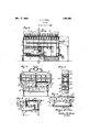
- Fig. l is a longitudinal section of one form of boiler embodying my invention
- Fig. 2 is a sectional view on the line 2-2 of Fig. 1;
- Fig. 3 is an enlargedl section on the line 3)*3 of Fig. 2;
- Fig. 4 is a detail sectional view showing a modification
- Fig. 5 is a partial view showing another modified form.
- my invention is shown as being applied to one of the usual types of sectional boilers formed of front sections 1 and rear sections 2 and intermediate sections 3. These sections are so formed and assembled as to provide a re box i in which is arranged the usual grate 5 and smoke fines 6 extending from the rear of the boiler forwaidly and smoke iiues 7 extending from the forward portion of the boiler rearwardly.
- the front and intermediate sections are preferably divided in halves for convenience in forming and handling and are hollow to provide suitable water ways for the water in the boiler.
- Each half section in the structure illustrated has side water ways 8 which extend downwardly into the side legs 9 and side water ways 10.
- the intermediate sections In addition to the water ways formed in the intermediate sections,
- cach half of one of the intermediate sections 11 in front of the usual bridge wall 12 is provided with transversely extending ⁇ hollow spaced apart ways 13 and 14C which at either end communicate with the water ways 9 and 10 and are arranged with their bottoms at a pointsubstantially in the same plane as the top of the bridge wall 12.
- These water ways are spaced apart to form an air throat 16 and are braced at intermediate points by the cross webs 17.
- closure and heating members 18 and 19 which extend between the top of the water ways 13 and 1i and the bottom of the cross water ways 2O immediately above.
- closure ⁇ members 18 and 19 are supported by the bottom water ways 13 and 14 which form water backed supports therefor and are held in position by means of cross bolts 21- preferably countersunk in the face of the closure menr bers.
- closure members are preferably formed of refractory material and form between them a secondary air conduit which receives the secondary air through suitable openings 22 formed in the side of the section.
- a slot or opening 23 which provides a communication between the top of the fire box and the secondary air chamber.
- the boiler In operation the boiler is fired in the usual manner with coal on the grate 5 and the main air supply passes up through the grate and fuel so that combustion takes place on the top of the fuel.
- the hot gases then pass backwardly impinginill,r against refractory cover plate 18 and passes beneath the de flector comprising the plates 18 and 19 and the water ways 13 and 141 thence back to the rear of the boiler thence forward through the smoke flue 6 and rearwardly again throue'h the smoke flue 7 to the smoke boX of the boiler.
- the refractory material of the covers 18 and 19 becomes highly heated by being in contact with the hot gases at this point and the interior of the secondary air passage is thus heated so that the secondary air which is drawn in through the openings 22 and passes between the cover plates 18 and 19 becomes highly heated before it is discharged through the throat 16 where it mingles with the burning gases passing beneath the deflector and supplies additional oxygen to assist in the combus tion of the gases and free carbon in the form of smoke passing therebeneath. Furthermore that portion of free carbon in the form ot smoke which accumulates in the top of the 1lire box is drawn in through the openings 23 and is additionally supplied with air i the secondary air passage so that it is supplied with sufficient oxygen to cause complete combustion whereby the boiler is rendered smokeless.
- the two. supporting cross members 13 and 14 being in the form ot water ways and the material therefor being water backed these members are prevented trom burning out. Furthermore the water contained in these cross water ways rapidly absorbs the heat trom the products of combustion.
- each of the intermediate sections having vertical water ways and transverse horizontal water ways extending between the vertical water ways, ot a pair ot integral supplemental horizontal water ways extending between and communicating with the vertical water ways of one of the interfmediate fire box sections, said supplemental water ways being spaced apart trom each other from front to rear to form therebetween a throat, and arranged below and space-d trom the bottom transverse water' way of the section, walls ormed'ot retractory material each supported on one of said supplemental water ways spaced apart from front to rear to torni an air passage therebetween and extending to the bottom transverse water way of the section to completely till the space between said transverse water way and the supplemental water ways, said air passage being arranged to have communication with the atmosphere.
- each ot the intermediate sections having vertical water ways and transverse horizontal water' ways, of a pair of' integral supplemental water ways extending between and communicating with the vertical water ways of one of the intermediate fire box sections, said supplemental waterways being spaced apart from front to rear to 'orm therebetween a throat and arranged below and spaced from the bottom transverse water way ot the section, and walls oit' refractory material each supported on one off said supplemental water ways and spaced apart from front to rear to form an air passage therebetween and extending to the bottom of the adjacent transverse waterway ot the section to completely ll the space between said transverse water way and the supplemental water ways, said air passage being arranged to communicate with the atmosphere and the front of said refractory walls being 'provided near the crown of the fire box with openings :tor connecting said air passages with the top ot the fire box.
Landscapes
- Engineering & Computer Science (AREA)
- Physics & Mathematics (AREA)
- Chemical & Material Sciences (AREA)
- Combustion & Propulsion (AREA)
- Thermal Sciences (AREA)
- Mechanical Engineering (AREA)
- General Engineering & Computer Science (AREA)
- Solid-Fuel Combustion (AREA)
Description
Patented N ov. 17, 1925.
HERMAN C. PROX, OF TERRE HAUTE, INDIANA.
BOILER,
Application filed July 3,
To (all fur/loin it may concern:
lle it known that I, HERMAN C. Pnox, a citizen of the United States, residing at Terre l-Iaute, in the county of Vigo and State of Indiana, have invented a new and useful Boiler, of which the following is a specification.
lily invention relates to improvements in hea-ting boilers and has for its object the prevention of undue smoke in the boiler during combustion of the fuel.
More particularly my invention has for its object to provide means for supplying in the combustion chamber preheated secondary air which when supplied to the products or combustion aids in lthe complete consumption of the smoke given off by fuel. A further object of my invention is to cause that portion of the smoke from the fuel which tends to rise to the top of the fire chamber to mingle with pre-heated secondary air so as to cause a complete combustion thereof.
For the purpose of disclosing my invention I have illustrated certain embodiments thereof in the accompanying drawings, in which:
Fig. l is a longitudinal section of one form of boiler embodying my invention; Fig. 2 is a sectional view on the line 2-2 of Fig. 1;
Fig. 3 is an enlargedl section on the line 3)*3 of Fig. 2;
Fig. 4 is a detail sectional view showing a modification; and
Fig. 5 is a partial view showing another modified form.
In the embodiment illustrated my invention is shown as being applied to one of the usual types of sectional boilers formed of front sections 1 and rear sections 2 and intermediate sections 3. These sections are so formed and assembled as to provide a re box i in which is arranged the usual grate 5 and smoke fines 6 extending from the rear of the boiler forwaidly and smoke iiues 7 extending from the forward portion of the boiler rearwardly. The front and intermediate sections are preferably divided in halves for convenience in forming and handling and are hollow to provide suitable water ways for the water in the boiler. Each half section in the structure illustrated has side water ways 8 which extend downwardly into the side legs 9 and side water ways 10. In addition to the water ways formed in the intermediate sections,
1922. Serial No. 572,537.
cach half of one of the intermediate sections 11 in front of the usual bridge wall 12 is provided with transversely extending` hollow spaced apart ways 13 and 14C which at either end communicate with the water ways 9 and 10 and are arranged with their bottoms at a pointsubstantially in the same plane as the top of the bridge wall 12. These water ways are spaced apart to form an air throat 16 and are braced at intermediate points by the cross webs 17.
Supported upon the water ways are closure and heating members 18 and 19 which extend between the top of the water ways 13 and 1i and the bottom of the cross water ways 2O immediately above. These closure ` members 18 and 19 are supported by the bottom water ways 13 and 14 which form water backed supports therefor and are held in position by means of cross bolts 21- preferably countersunk in the face of the closure menr bers. These closure members are preferably formed of refractory material and form between them a secondary air conduit which receives the secondary air through suitable openings 22 formed in the side of the section. At the top of the front cover member 18 is formed a slot or opening 23 which provides a communication between the top of the fire box and the secondary air chamber.
In operation the boiler is fired in the usual manner with coal on the grate 5 and the main air supply passes up through the grate and fuel so that combustion takes place on the top of the fuel. The hot gases then pass backwardly impinginill,r against refractory cover plate 18 and passes beneath the de flector comprising the plates 18 and 19 and the water ways 13 and 141 thence back to the rear of the boiler thence forward through the smoke flue 6 and rearwardly again throue'h the smoke flue 7 to the smoke boX of the boiler. The refractory material of the covers 18 and 19 becomes highly heated by being in contact with the hot gases at this point and the interior of the secondary air passage is thus heated so that the secondary air which is drawn in through the openings 22 and passes between the cover plates 18 and 19 becomes highly heated before it is discharged through the throat 16 where it mingles with the burning gases passing beneath the deflector and supplies additional oxygen to assist in the combus tion of the gases and free carbon in the form of smoke passing therebeneath. Furthermore that portion of free carbon in the form ot smoke which accumulates in the top of the 1lire box is drawn in through the openings 23 and is additionally supplied with air i the secondary air passage so that it is supplied with sufficient oxygen to cause complete combustion whereby the boiler is rendered smokeless. The two. supporting cross members 13 and 14 being in the form ot water ways and the material therefor being water backed these members are prevented trom burning out. Furthermore the water contained in these cross water ways rapidly absorbs the heat trom the products of combustion.
In the structure shown in Fig. a the secondary air instead of being taken in through a passage formed in the side ot the section is taken in through a vertically extending passage or opening 24 communicating with the ash pit.
l claim as my invention:
l. In a sectional boiler the combination with front andV rear sections and intermediate sections, each of the intermediate sections having vertical water ways and transverse horizontal water ways extending between the vertical water ways, ot a pair ot integral supplemental horizontal water ways extending between and communicating with the vertical water ways of one of the interfmediate lire box sections, said supplemental water ways being spaced apart trom each other from front to rear to form therebetween a throat, and arranged below and space-d trom the bottom transverse water' way of the section, walls ormed'ot retractory material each supported on one of said supplemental water ways spaced apart from front to rear to torni an air passage therebetween and extending to the bottom transverse water way of the section to completely till the space between said transverse water way and the supplemental water ways, said air passage being arranged to have communication with the atmosphere.
2. In a sectional boiler, the combination with front and rear sections and intermediate sections, each ot the intermediate sections having vertical water ways and transverse horizontal water' ways, of a pair of' integral supplemental water ways extending between and communicating with the vertical water ways of one of the intermediate lire box sections, said supplemental waterways being spaced apart from front to rear to 'orm therebetween a throat and arranged below and spaced from the bottom transverse water way ot the section, and walls oit' refractory material each supported on one off said supplemental water ways and spaced apart from front to rear to form an air passage therebetween and extending to the bottom of the adjacent transverse waterway ot the section to completely ll the space between said transverse water way and the supplemental water ways, said air passage being arranged to communicate with the atmosphere and the front of said refractory walls being 'provided near the crown of the lire box with openings :tor connecting said air passages with the top ot the fire box.
In witness whereof, l, HERMAN C. PROX, have hereunto set my hand at Terre Haute, lndiana, this 30th day ot June, A. D. one thousand nine hundred and twenty two.
HERMAN C. PROX.
Priority Applications (1)
| Application Number | Priority Date | Filing Date | Title |
|---|---|---|---|
| US572537A US1561663A (en) | 1922-07-03 | 1922-07-03 | Boiler |
Applications Claiming Priority (1)
| Application Number | Priority Date | Filing Date | Title |
|---|---|---|---|
| US572537A US1561663A (en) | 1922-07-03 | 1922-07-03 | Boiler |
Publications (1)
| Publication Number | Publication Date |
|---|---|
| US1561663A true US1561663A (en) | 1925-11-17 |
Family
ID=24288267
Family Applications (1)
| Application Number | Title | Priority Date | Filing Date |
|---|---|---|---|
| US572537A Expired - Lifetime US1561663A (en) | 1922-07-03 | 1922-07-03 | Boiler |
Country Status (1)
| Country | Link |
|---|---|
| US (1) | US1561663A (en) |
Cited By (1)
| Publication number | Priority date | Publication date | Assignee | Title |
|---|---|---|---|---|
| US4449485A (en) * | 1982-07-20 | 1984-05-22 | Tan P Lu John | Separable combination boiler |
-
1922
- 1922-07-03 US US572537A patent/US1561663A/en not_active Expired - Lifetime
Cited By (1)
| Publication number | Priority date | Publication date | Assignee | Title |
|---|---|---|---|---|
| US4449485A (en) * | 1982-07-20 | 1984-05-22 | Tan P Lu John | Separable combination boiler |
Similar Documents
| Publication | Publication Date | Title |
|---|---|---|
| US1561663A (en) | Boiler | |
| US1311522A (en) | jones | |
| US1690260A (en) | Boiler furnace and garbage incinerator | |
| US409285A (en) | Sawdust-burner | |
| US973112A (en) | Oil-burning locomotive-furnace. | |
| US546438A (en) | Garbage-furnace | |
| US413832A (en) | Garbage-cremating furnace | |
| US1699223A (en) | Boiler | |
| US1664099A (en) | Oil-burning locomotive furnace | |
| US768851A (en) | Furnace. | |
| US1502575A (en) | Combination coal and gas heater | |
| US1726527A (en) | Heating apparatus | |
| US1724462A (en) | Sectional furnace | |
| US1972073A (en) | Cremation furnace | |
| US263552A (en) | Stove or furnace | |
| US505143A (en) | Furnace | |
| US2136175A (en) | Boiler | |
| GB267951A (en) | Improvements in heating apparatus such as furnaces, stoves, slow combustion stoves and the like for use with solid fuel | |
| US1394508A (en) | Stove | |
| US507938A (en) | Steam-boiler furnace | |
| US542294A (en) | Smokeless furnace | |
| US721329A (en) | Furnace. | |
| US287656A (en) | Furnace | |
| US750860A (en) | Smoke-consumer | |
| US519658A (en) | Smokeless boiler-setting |