US1552016A - Thread-cutting temple for looms - Google Patents
Thread-cutting temple for looms Download PDFInfo
- Publication number
- US1552016A US1552016A US738682A US73868224A US1552016A US 1552016 A US1552016 A US 1552016A US 738682 A US738682 A US 738682A US 73868224 A US73868224 A US 73868224A US 1552016 A US1552016 A US 1552016A
- Authority
- US
- United States
- Prior art keywords
- controller
- operative
- inoperative
- temple
- loom
- Prior art date
- Legal status (The legal status is an assumption and is not a legal conclusion. Google has not performed a legal analysis and makes no representation as to the accuracy of the status listed.)
- Expired - Lifetime
Links
- 238000010276 construction Methods 0.000 description 11
- 230000000694 effects Effects 0.000 description 8
- 210000000481 breast Anatomy 0.000 description 2
- 230000002035 prolonged effect Effects 0.000 description 2
- 101100020619 Arabidopsis thaliana LATE gene Proteins 0.000 description 1
- 206010030113 Oedema Diseases 0.000 description 1
- 239000000969 carrier Substances 0.000 description 1
- 238000004140 cleaning Methods 0.000 description 1
- 230000000994 depressogenic effect Effects 0.000 description 1
- 229920000136 polysorbate Polymers 0.000 description 1
- 238000009877 rendering Methods 0.000 description 1
- 230000000284 resting effect Effects 0.000 description 1
- 239000011435 rock Substances 0.000 description 1
- 230000035939 shock Effects 0.000 description 1
Images


Classifications
-
- D—TEXTILES; PAPER
- D03—WEAVING
- D03D—WOVEN FABRICS; METHODS OF WEAVING; LOOMS
- D03D49/00—Details or constructional features not specially adapted for looms of a particular type
- D03D49/70—Devices for cutting weft threads
Definitions
- the Well-known purpose of the thread cutting temple is to cut off close to the selvage the filling ends left after replenishment ofthe filling.
- One end is left by the discharged filling carrier and another end 1s left extending from the first pick made by the fresh filling carrier.
- replenishment of filling only takes place.
- the cutting mechanism carried by 'the temple it is the usual practice for the cutting mechanism carried by 'the temple to be operated at each beat up ofk the lay. Hence the cutting lmechanism is subject to a large amount of unnecessary wear.
- suc-h means have been associated so closely with the temple itself as to render it necessary to ⁇ provide a comparatively small and more or less delicate mechanism.
- the main object of this invention is to provide a mechanism which shall be made relatively largel and 'rugged and ofsuch nature so as to stand up under the wear and shock of the loom operation.
- This main object of the invention is secured by mounting a controller or controlling mechanismen a fixed part of the loom. 'This enables it to be placed at any conven- OF HOPEDALE, MASSACHUSETTS; BY WAI.- LACE I. STIlMPSON,v EXECUTOR, OF HOPEDALE, MASSACHUSETTS, ASSIGNOR TO LE, MASSACHUSETTS, CORPORATION OF TEMPLE FOR LOOMS.
- This controller has an operative Veffecting inoperative effecting position, and it is movable when in, operative effecting position.
- Suitable means are provided actuated by or throughffthe movement of the replenishing mechanism to shift this controller from its inoperative i effecting position to itsr operative effecting position.
- Means are also providedactuated by a moving part of the loom, such as the lay, to move the 4controller gradually through its operative effecting position into its inoperative effecting position. bothof these means may be made of av relatively large size and of rugged construction.
- the controlling movements of the ,controller are transmitted throughV suitable transmitting mechanism, preferably of a flexible nature, from the fixed location vof the controller, wherever situated, to the filling cutting mechanism carried b-y the movable temple and movable itself temple. l
- the invention thus provides fa principle of construction .involving the controller mounted in fixed position, the filling cutting mechanism mounted ony the movable temple and itself movable withl respect to the temple, and the tnansmitting mechanism which enables the desired intermittent with respect to the secured ly andl which 'enables the mechanism to be made of durable ⁇ and rugged construction.
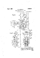
- V17 carried the transterrer
- Figll isa view partially in vertical cross section looking Vtoward the inside "ot the loom toward the replenishing side with parts
- Fig. Q is a view Vsimilar to Fig. 1 on its connections, with the casing ot' the controller removed.
- Fig. 3 is a ront elevation of the construction shown in Fig. 2 with' the casing 'in place.
- rFig. 4 is a view in horizontal cross section taken von line of Fig. 2.V
- FIG. 5 is a. view incr-oss section taken on 2.
- a Fig. i6 is a view in side elevation oit the temple vlooking atthe. side opposite to that shown in, Fig. 1 and with the thread cutytingmechanism shown in inoperative posi tion.
- Fig. 7 is a view similar to Fig. "6 with the 'thread cutting inechanism'sh'own in operative position. Y
- the loom comprises the usual 'frame hav- 1, only one of which is illustrated, connected at the front by the breast beam, 2.
- the lay, 3, is carried by the lay' swords, 1, pivoted on the shaft, 5, ciztending' between the side'ira-mes, 1, and is swung toward and from the breast beam by the usual connection, ⁇ 6.
- the supply o Yiiresh filling carriers, 7, is maintained in 'a hopper, 8, mounted at Athe iepleiiisliiiigs ⁇ ide oi the Vvlhen :the .iilling in the running shuttle, 9, 'is substantially exhausted, suitable detecting mechanism actuates theintermittent fiilling replenishment by rocking "in a clockwise direction the rock shaft, 10.
- the'lay is conveniently utilized to ei'lect the movement of the controller into'the inoperative effecting position.
- the thread cutting mechanism is carried by the temple so as to have its iield of operati-on close t0 the selvage and adjacent to the tell. type.
- the important thing to note in con-V rl ⁇ his mechanism may be of any nection with this invention is ⁇ that this cutting mechanism is Acarried by the templeand reciprocated with the temple with each beat up ot the lay. lt is 9'? also important to noteA that in order that termittent action, that is, be operative during certain predetermined periods and inoperative during the remaining time, it must have the required inhave an operative position and an inoperavFor convenience in illustrating the present invention, a familiar type oi thread cutting mechanism. is shown.
- lt comprises 'a fixed vertical cutting blade,'23, in a slot in tive movable cutting j ableV blade, 2l, extends through the temple iead, guided by a ⁇ slot therein and is provided with a depending heel, 25.
- a second lever, 32 is ⁇ fulcrumed at 33 on the temple stand and carries on its rearward end a stud, 34, engaging a slot in the forward end of the lever,y 29.
- a helical spring, 35 seated at one end in a socket in a lug, 36, on the temple stand and seated at the other end in a socket in the forward end of the lever, 32, acts normally to press the forward end of the lever, 32 against a lug, 37, on the temple stand and thus to depress the hooked endof the detent latch, 29, into detaining engagement with the stud, 31.
- the transmitting means already referred to, and hereinafter described, acts to raise the forward end of the lever, 32, against the spring, 35, and thus to release the detent latch from the stud, 31.
- the controller or controlling mechanism,
- FIG. 1 A base plate orbracket, 38, is rigidlyand adjustably secured.. asbymeansof the set screws, 39, passing through the slots, 40, therein, tothe side of the frame, 1.
- the base plate, 38 has rigidly secured therein y the reduced portion 41 of the stub shaft, 42,
- the main controlling elenient which is in the form of acombined cam and mutilated ratchet wheel.
- cam is shown as having the concentric portions, 45, and re-entrant portions, 46.- A
- the ratchet wheelfis provided with ratchet teeth,.49 which, when acted upon, move the cam step by ⁇ step with the concentric portion, 45, in contact with the follower and until the follower dropsy intogthe re-entrant portion, 46. It is lalso provided with a mutilated portion, 50,' which prevents operation ofthe ratchet wheel when the follower has dropped into the re-entrant portion, 46.
- the follower, 47, A is in a re-entrant portion, 46, of the cani it is in its inoperative effecting position.
- the controller may be gradually moved without affecting the position of the follower until the inoperative effecting position is reached.
- a pawl mecha- ⁇ nisrn is provided actuated by or through the For thisk lling replenishing mechanism.
- a hook-shaped pawl, 51 is mounted in vertical'position and loosely guided on a stud, 52, projecting from the base plate,38. This pawl is conveniently suspended by a rod, 53, from the stud, 54, on the shuttlefeeler, l2, engaged by the arm, 11.
- the pawl, 51 is shown at one side of the pawl, 55,Y and in order to get a direct pull ,on the pawl, 51, a few of the ratchet teeth as 57, are'widened to come in line with the path ofthe pawl, 51.
- yThe pivotal connection of the pawl, 55, withthe lay sword, 4, illusyeo trated, is sho-wn separately in Fig. 4.
- a twoj fpart clamping bracket, 58 and 59 is clamped over the flange, 60, of the lay sword and held inplace by a shaft or rod, 61, passing there through and -provided near one end with a fixed collar, 63, and at the other end with a nut, 64, threaded thereon.
- Theend of the rod, 61 is prolonged beyond'the collar at the end 63, and on this prolonged portion 65 is loosely fastened the hub, 66, of
- rfhe transmitting means by which movement is transmitted fromj the controller mounted in a fixed position on a convenient part of the loom to the cutting mechanism carried by the in table temple includes the detent 'latch or device already described and a flexible transmitting connection, which, in the preferred form illustrated, is shown as what is known as a Bowden wire.
- This device comprises a flexible outer shaft YKformed of a wire, both ends of which are'fixedly supported, and an interior wire plunger. This construction enablesa thrust or a pull to .be transmitted through the interior wire while the entire device may be bent or twisted as required.
- a lug, 74 projecting from 88, above the rearward end wire 7 5, sits at its upper and sits at Vits lower end in a de- 77, in the top of the rear end of the follower, 47.
- the operation of the mechanism will now be apparent. Inf all the 7, the parts are in thek position they normally occupy when the loom is ruiming or, in other words, the cutting mechanism is in ⁇ inoperative position, the movable blade, 24, ⁇ being' held forwardly by thedetent latch, V29, and the follower, 47, resting in the re-entrant portion, 46, of the cam and the actuating pawl, 55, moving' idly in the mutilated portion ofthe ratchet wheel.
- ll/Vhen replenishment is lever, 32, pression,
- Thelclainping device, 58, '59 varies the throw of the pawl according to its vertical position on the lay and the size and number of teeth may be ⁇ designed as rcquired.
- a loom comprisingy automatic ⁇ filling replenishing mechanism; a 4temple mounted 1 for reciprocating movement .on a fixed vpart of the loom;l filling cutting mechanism ,carried by the temple and movable with respect l*thereto into operative and inoperative positions; a controller mounted ⁇ on a fixed part of the loom, having operative effecting and inoperative effecting positions and movable when in, and without aecting, ,the operative effecting position; me ns actuated by or through the movement of the replenishing mechanism to shift the controller' from inoperative effecting posit-ion to operative effecting position; means actuated by a -moving part of the loom to move the controller gradually through operative effecting position into inoperative effectingposition; and transmittingmeans between the controller and the cutting mechanism acting upon the said shifting of the controller to effect the movement of the filling cutting mechanism into operative position.
- a loom comprising automatic filling replenishing mechanism; a temple mounted for reciprocating movement on a Xed part of the loom; lling cutting mechanism carried bythe temple and movable with respect thereto into operative and inoperative tions; controller. mounted on a fixed part of the loom, having operative eecting and inoperative effecting positions and imovable when.
- a loom comprising automatic filling replenishing mechanism; a temple mounted for reciprocating movement on a, fixed part of the loom; filling cutting mechanism carried by the temple and movable with respect thereto into operative and inoperative positions; detent means for retaining the cutting mechanism in inoperation position; a controller mounted on a.
- a loom comprising the lconstruction defined in claim 4; together with moans actingl normally to move the detent means into detaining position; and in whichtlie flexible transmitting connection also acts upon the movement of the controller into inoperative effecting position to permit the said detent means to move into and remain in detaining position and thus to permit the ilingv cutting mechanism to move into and remain in inoperative'position.
- a loom comprising automatic filling replenishingmechanism; a temple mounted for reciprocating movement on a fixed part of thev loom; filling cutting mechanism car- I ried bythe temple and movable with respect thereto into operative and inoperative positions; a Acontroller comprisinga combined cam and mutilated ratchet wheel journaled on a fiXed part of the loom; a follower for the cam; a pawl actuated by'a moving part ofthe loom and acting Ywhen in engagement with the ratchet teeth to rotate the controller step by step; a second pawl'actuated by or through the movement of thereplenishing mechanism to engage the ratchet teeth and rotate the controller to bring the ratchet teeth into engagement with the first pawl;
- the said cam acting to effect the movement of the follower in one direction when the controller is rotated by the second pawl ⁇ and in the opposite direction at the end ofthe rotation of the controller by the first pawl; and transmitting means between the follower and the cutting mechanism acting upon the movement ofthe follower in the first direction to effect the movement of the cutting mechanism into operative position and act-ing upon the movement ⁇ of the follower in the opposite direction to effect the movement of t-he cutting mechanism into inoperative position.
- loom comprising a frame; a lay;
- a temple mounted for reciprocating move-v ment on the frame; filling .cutting mechanism carried by the temple and movable'by the lay into inoperative position; a spring controlled detent latch acting to retain the cutting mechanism in Vinoperative position;
- a contro-ller comprising a combined cam and mutilated ratchet wheel journaled on theV frame; a follower for the cam;v a pawl car- I ried by the lay and acting when 1n engageratchet teeth to rotate'the controller step by step; a second pawl actuated by or through the movementof( the replenishing mechanism to engage the ratchet teeth and rotate the cont-roller to lbring the teeth vintoengagement with the rst pawl; the
- a loom comprising automatic iilling replenishing mechanism, a temple filling cutter, a detent for normally holding said cutter in inoperativev position, a controller mounted on a fixed part of the loom :tor controlling the position of said detent, conmech-anism between said detent and controller by or through the filling replenishingfmechanism to release said detent and permit the cutter to operate,y and means whereby saidy controllery retains said detent l etlecting position from holding engagement with the cutter for a predetermined periodV following replenishment.
- a loom comprising replenishing mechanism, a temple filling cutter, movable means Jfor holding the cutter in inoperative position, a controller on a xed ,part of the loom having operative effecting and inoperative effecting positions ⁇ means actuated by or through movement of the replenishing mechanism to position the.
- controller in operative eiecting position ⁇ means to place said/controller in inoperative after a predetermined number of beats of the lay, and transmitting or connecting means between the controller and the said cutter holding means whereby the cutter may be normally held inoperative and be rendered operative :tor a predetermined period ollowing replenishment.
Landscapes
- Engineering & Computer Science (AREA)
- Textile Engineering (AREA)
- Looms (AREA)
Description
E. S. STIMPSQN THREAD CUTTING TEMPLE FOR 1100145 Sewv 1, 1925-.
3 Shams-Sheet 2 Filed Sept. 19, 1924 Ibn Sqn, l, 192s. i 1,552,016'
' E. s. sTmPsoN THREAD CUTTING TEIPLE FOR LOGIS Filed Sept. 19, 1924 3 Sheets-Sheetl 3 Patented Sept. l, 19275.
UNITED STATES PATENT, oFFIolaz.v
EDWARD S. STIMISON. DECEASED, LATE DRAPER CORPORATION, OF HOPEDA MAINE. A
- THREAD-CUTTIN G Application filedk September mechanism shall be operative for a prede-v termined period after the operation of the filling replenishing mechanism and shall then be rendered inoperative until the next call for filling replenishment, or in other words, an intermittently operative thread cutting temple.
The Well-known purpose of the thread cutting temple is to cut off close to the selvage the filling ends left after replenishment ofthe filling. One end is left by the discharged filling carrier and another end 1s left extending from the first pick made by the fresh filling carrier. Notwithstanding the fact that replenishment of filling only takes place. occasionally during the operation of the loom, it is the usual practice for the cutting mechanism carried by 'the temple to be operated at each beat up ofk the lay. Hence the cutting lmechanism is subject to a large amount of unnecessary wear. While means have heretofore been provided for rendering the operation of the cutting mechanism intermittent so as to act only for short periods after replenishment, or after the call for replenishment, suc-h means have been associated so closely with the temple itself as to render it necessary to` provide a comparatively small and more or less delicate mechanism.
The main object of this invention is to provide a mechanism which shall be made relatively largel and 'rugged and ofsuch nature so as to stand up under the wear and shock of the loom operation.
This main object of the invention is secured by mounting a controller or controlling mechanismen a fixed part of the loom. 'This enables it to be placed at any conven- OF HOPEDALE, MASSACHUSETTS; BY WAI.- LACE I. STIlMPSON,v EXECUTOR, OF HOPEDALE, MASSACHUSETTS, ASSIGNOR TO LE, MASSACHUSETTS, CORPORATION OF TEMPLE FOR LOOMS.
19, 1924. Serial- No. 738,682.
ient Yposition and to be made of la-rgesize and of rugged construction. This controller has an operative Veffecting inoperative effecting position, and it is movable when in, operative effecting position. Suitable means are provided actuated by or throughffthe movement of the replenishing mechanism to shift this controller from its inoperative i effecting position to itsr operative effecting position. Means are also providedactuated by a moving part of the loom, such as the lay, to move the 4controller gradually through its operative effecting position into its inoperative effecting position. bothof these means may be made of av relatively large size and of rugged construction.
The controlling movements of the ,controller are transmitted throughV suitable transmitting mechanism, preferably of a flexible nature, from the fixed location vof the controller, wherever situated, to the filling cutting mechanism carried b-y the movable temple and movable itself temple. l
The invention thus provides fa principle of construction .involving the controller mounted in fixed position, the filling cutting mechanism mounted ony the movable temple and itself movable withl respect to the temple, and the tnansmitting mechanism which enables the desired intermittent with respect to the secured eficiently andl which 'enables the mechanism to be made of durable` and rugged construction.
These and other objects' and features of the invention will appear more fully from the accompanying description anddrawings and will be particularly pointed outin the claims. Y
As the general operation and construction Thusy position and an i and without affecting; the
operation of the cutting mechanism to be i of the automatic filling replenishing loom y i and of the thread cutting temple are 'well known and familiar to those skilledin the art, it is only necessary to illustrate andfdescribe inl detail those parts directly concerned with the present invention. I
The drawings, therefore, illustrate fso much o-f a filling replenishing loom of the well-known Northroptype as is sufficient to disclose a vention. v
preferred yform ofthepresent ini `broken away or removed.V
vlarger scale, showing the `controller and ing the side frames,
swings the shuttle-teeler,
V17, carried the transterrer,
ent invention, detail because, in the particular embodiment In the drawings:
Figll isa view partially in vertical cross section looking Vtoward the inside "ot the loom toward the replenishing side with parts Fig. Q is a view Vsimilar to Fig. 1 on its connections, with the casing ot' the controller removed.
Fig. 3 is a ront elevation of the construction shown in Fig. 2 with' the casing 'in place.
rFig. 4: is a view in horizontal cross section taken von line of Fig. 2.V
AFig. 5 is a. view incr-oss section taken on 2.A Fig. i6 is a view in side elevation oit the temple vlooking atthe. side opposite to that shown in, Fig. 1 and with the thread cutytingmechanism shown in inoperative posi tion.
Fig. 7 is a view similar to Fig. "6 with the 'thread cutting inechanism'sh'own in operative position. Y
The loom comprises the usual 'frame hav- 1, only one of which is illustrated, connected at the front by the breast beam, 2. The lay, 3, is carried by the lay' swords, 1, pivoted on the shaft, 5, ciztending' between the side'ira-mes, 1, and is swung toward and from the breast beam by the usual connection,`6. The supply o Yiiresh filling carriers, 7, is maintained in 'a hopper, 8, mounted at Athe iepleiiisliiiigs`ide oi the Vvlhen :the .iilling in the running shuttle, 9, 'is substantially exhausted, suitable detecting mechanism actuates theintermittent fiilling replenishment by rocking "in a clockwise direction the rock shaft, 10.
In the vform ofthe loom illustrated, when the shaft, '10, isY rocked, it Vraises the arm, l1, connected Vvthereto and this arm in turn 12, rearwardly about its pivot, `Then the shuttle-tecla', 12, is thusswung rearwardly, it raises a dog,
111, pivoted at 15 to the transterrer, 16, so
asto bring this dog into the path oit a bunter, by the lay. c, "Consequently, as .the lay'beats up after the call for replenishment, the bunter, 17, strikes the dog, 14, and`v ca ses 16, to swing downwardly and vtorce theresh filling carrier, 7, into the shuttle, 9, rand discharge vironi the Vshuttle the exhausted filling carrier.
. 4`While the. foregoing mechanism, specitically considered, forms no part of the presit is described somewhat in of the illustration, themovemeiit of the sliuttle-'eeler is conveniently utilized 'to effect the shitting ot the controller into the operative effecting position and thefmovement oi,
the'lay is conveniently utilized to ei'lect the movement of the controller into'the inoperative effecting position.
Y is consequently bodily this mechanism may 'the movable blade,
miliar ma-nner. f
The thread cutting mechanism is carried by the temple so as to have its iield of operati-on close t0 the selvage and adjacent to the tell. type. The important thing to note in con-V rl`his mechanism may be of any nection with this invention is `that this cutting mechanism is Acarried by the templeand reciprocated with the temple with each beat up ot the lay. lt is 9'? also important to noteA that in order that termittent action, that is, be operative during certain predetermined periods and inoperative during the remaining time, it must have the required inhave an operative position and an inoperavFor convenience in illustrating the present invention, a familiar type oi thread cutting mechanism. is shown. lt comprises 'a fixed vertical cutting blade,'23, in a slot in tive movable cutting j ableV blade, 2l, extends through the temple iead, guided by a` slot therein and is provided with a depending heel, 25. A. spring, 26, connected to' a stud, 21.7,. on the tempie tive position.
arm, 20, and to a stud, 2S, on the heel, 25,
acts normally to project the movable blade, 2l, rearwardly or into the position shown in Fig. 7. lWhen the 1eat'ter the lay beats up, it strikes the heel, 25, and swings Vthe movable blade, 2l, downwardly Aand forwardly and the filling end caught between it and 'the lined blade, 23, is sheared oil' closeV to the selvage.
lt will thusV be mechanism, each seen that, with this type olf 2l, is projected by the spring rearwardly int-o operative position so vthat each time the lay beats up, the heel, 25, y
the temple head and acooperablade, 2l. rlhe movf time the lay. swings back of the movable blade is struck and the cutn ting mechanism operated. l3nt, as pointed out, this movement ot the cutting-meel anisni is only necessary immediately after filling replenishment takes place, an operation which occurs at widely separated intervals in the operation ol' the loom. In eti'ecting a simple and preferred emb-odiment of the present invention in connecti-on with the particular type of threadr cutting temple'illustrated,.a simple forni ot detent latch is provided to retain the cutting mechanism in inoperative position. This detent latch, 29, is shown injtheiiform of a lever ulcrumed at 30 onthe'ptemple'stand,
18, and hook shaped at its rearward end to cooperate with a stud, 31, projecting from the forward end of the movable cutting member, 24. A second lever, 32, is` fulcrumed at 33 on the temple stand and carries on its rearward end a stud, 34, engaging a slot in the forward end of the lever,y 29. A helical spring, 35, seated at one end in a socket in a lug, 36, on the temple stand and seated at the other end in a socket in the forward end of the lever, 32, acts normally to press the forward end of the lever, 32 against a lug, 37, on the temple stand and thus to depress the hooked endof the detent latch, 29, into detaining engagement with the stud, 31. The transmitting means already referred to, and hereinafter described, acts to raise the forward end of the lever, 32, against the spring, 35, and thus to release the detent latch from the stud, 31.
The controller, or controlling mechanism,
is essentially mounted on a fixed part of the loom and in a position where it can be made of large and rugged construction and be operated from this moving part of the loom. In the preferred construction illustrated, it is conveniently located at the bottom of the loom on the side frame, 1, where there is plenty of room'and where it may be operated from a pawl carried by the lay.
rlhis location is shown'in Fig. 1, and the details of the specific form of the .features illustrated are shown in 2 5, inclusive. A base plate orbracket, 38, is rigidlyand adjustably secured.. asbymeansof the set screws, 39, passing through the slots, 40, therein, tothe side of the frame, 1.
The base plate, 38, has rigidly secured therein y the reduced portion 41 of the stub shaft, 42,
having a reduced threaded outer end, 43,
upon which is mountedcthe nut, 44, Upon this shaft, 42, is mounted the main controlling elenient which is in the form of acombined cam and mutilated ratchet wheel. The
.is in the inoperative effecting position.
cam is shown as having the concentric portions, 45, and re-entrant portions, 46.- A
follower, 47, is pivoted at 48 on thefbase plate, 38, and it vwill thus be seen that as vthe cam rotates withthe portion, 45, in contact with the follower, this followerreniains nnmoved in its elevated position and that as a ire-entrant portion, 46, comes opposite `the follower, this follower will move into the depressed position. `The number ofv times that the concentric and re-entrant portions of the cam are repeated is, of course, immaterial, and herein they are shownrepeated twice, so that `two ,similar cycles of voperation successively take place during one rotation of the cam'. The ratchet wheelfis provided with ratchet teeth,.49 which, when acted upon, move the cam step by `step with the concentric portion, 45, in contact with the follower and until the follower dropsy intogthe re-entrant portion, 46. It is lalso provided with a mutilated portion, 50,' which prevents operation ofthe ratchet wheel when the follower has dropped into the re-entrant portion, 46.
llVhen the follower, 47, Ais in a re-entrant portion, 46, of the cani it is in its inoperative effecting position. When the follower is in contact with the concentric portion of the cam, 45, it is in its operative effecting position and it will be noted that when it is in its latter position the controller may be gradually moved without affecting the position of the follower until the inoperative effecting position is reached.
f n order toelfect the shifting of the controller from inoperative effecting positiony. to operative effecting position a pawl mecha- `nisrn is provided actuated by or through the For thisk lling replenishing mechanism. j purpose a hook-shaped pawl, 51, is mounted in vertical'position and loosely guided on a stud, 52, projecting from the base plate,38. This pawl is conveniently suspended by a rod, 53, from the stud, 54, on the shuttlefeeler, l2, engaged by the arm, 11. Conse- 1 quently, when filling replenishment is called for and the shuttle-feeler swings rearwardly, this stud, 54, is raised and the rod, 53, raises thev pawl,51, which thereupon shifts the controlling ratchet wheel sufficientlyv to cause the concentric portion, 45, of the `cam to lride beneath and elevate the follower, 47.
The pawl, 51, is shown at one side of the pawl, 55,Y and in order to get a direct pull ,on the pawl, 51, a few of the ratchet teeth as 57, are'widened to come in line with the path ofthe pawl, 51. yThe pivotal connection of the pawl, 55, withthe lay sword, 4, illusyeo trated, is sho-wn separately in Fig. 4. A twoj fpart clamping bracket, 58 and 59, is clamped over the flange, 60, of the lay sword and held inplace by a shaft or rod, 61, passing there through and -provided near one end with a fixed collar, 63, and at the other end with a nut, 64, threaded thereon. Theend of the rod, 61, is prolonged beyond'the collar at the end 63, and on this prolonged portion 65 is loosely fastened the hub, 66, of
' the pawl, 55.
' A casing cover, 67, lits .over the controlling mechanism and is held in place by the nut, 44.'l This cover isalso utilized to mainf of the follower,
figures of drawing except Fig.
beneath the follower, 47,
lower, 47,
different movable parts of the mechi` the base plate. helisn'ine, GS, a l @tween the cover', 67, and the hub, (39, of the combined cani and ratchet wheel, holds that member loosely in place. The cover also holds the pawls, 5i and 55, and the follower, 47, on their respective studs. This enables the various parts to fit loosely and move freely and also enables the mechanism readily to be taken apart for cleaning or repair.
rfhe transmitting means by which movement is transmitted fromj the controller mounted in a fixed position on a convenient part of the loom to the cutting mechanism carried by the in table temple includes the detent 'latch or device already described and a flexible transmitting connection, which, in the preferred form illustrated, is shown as what is known as a Bowden wire. This device comprises a flexible outer shaft YKformed of a wire, both ends of which are'fixedly supported, and an interior wire plunger. This construction enablesa thrust or a pull to .be transmitted through the interior wire while the entire device may be bent or twisted as required.
ln the construction illustrated the yupper end of the shaft, YO, of the Bowden wire is sleeve, 7i, by a set screw,
clamped in a split on the temple stand while 72', in the lug, 37, the lower end set screw, 73, in a bracket plate,
a lug, 74, projecting from 88, above the rearward end wire 7 5, sits at its upper and sits at Vits lower end in a de- 77, in the top of the rear end of the follower, 47. The operation of the mechanism will now be apparent. Inf all the 7, the parts are in thek position they normally occupy when the loom is ruiming or, in other words, the cutting mechanism is in `inoperative position, the movable blade, 24, `being' held forwardly by thedetent latch, V29, and the follower, 47, resting in the re-entrant portion, 46, of the cam and the actuating pawl, 55, moving' idly in the mutilated portion ofthe ratchet wheel. ll/Vhen replenishment is lever, 32, pression,
Vcalled for the shaft l0 is rocked, the shuttlefeeler, 12, is swung rearwardly, the rod, 5S, is raised, the pawl 5l catching on one of the teeth 57, shifts the controller suiiiciently to bring the concentric portion of the cam, 45, and to bring the teeth, 5 1, intoA position to be caught by the pawl, 55. The movement thusy given the folis transmitted through the Bowden wire rocking the'lever, 32, and releasing the detent latch, 29 thus allowing the movable cutter blade, '.24, under the action of its spring, 26, to be projected into operative position. The parts are then as shown in issimilarly clamped by the.
47. The interior or thrustend in a depression, 17 6, in the bottom of the forward end of the f7. `fit each beat ,up .of the lay lthatnow ies :piace lthe cutting mechanism is .oper-- .ated in the manner-and the controller is moved step :by step through the pawl, v55, and .until the next ite-entrant portion 46 of lthe cam, 45, .and the mutilated portion 5.() of the ratchet is reached, when ,the .parts are again restored to inoperative position. The number .of operations thus ,given will ,de-
end on the number of teeth on the ratchet wheel between successive mutilated portions vand the .eat-ent .of movement of the actuating pawl, lboth of which may ,be varied ,as desired. Thelclainping device, 58, '59, varies the throw of the pawl according to its vertical position on the lay and the size and number of teeth may be` designed as rcquired. c
ihere is thus produced a mechanism-,in which theccntrolling elements maybe located atany desired position on the lloom `and may Vbe made of large rugged ,and ldurable construction. Thusthese parts may be made subject to a minimum amount of wear and may have an easy t and a wide range of movement, since the only movement transmitted to the cutting mechanism isthe movement .given to the cam follower.
Having thus described the invention, what is claimed as new, and desired to .be secured by Letters Patent, is: Y
l. A loom comprisingy automatic `filling replenishing mechanism; a 4temple mounted 1 for reciprocating movement .on a fixed vpart of the loom;l filling cutting mechanism ,carried by the temple and movable with respect l*thereto into operative and inoperative positions; a controller mounted `on a fixed part of the loom, having operative effecting and inoperative effecting positions and movable when in, and without aecting, ,the operative effecting position; me ns actuated by or through the movement of the replenishing mechanism to shift the controller' from inoperative effecting posit-ion to operative effecting position; means actuated by a -moving part of the loom to move the controller gradually through operative effecting position into inoperative effectingposition; and transmittingmeans between the controller and the cutting mechanism acting upon the said shifting of the controller to effect the movement of the filling cutting mechanism into operative position.
2. A loom comprising automatic filling replenishing mechanism; a temple mounted for reciprocating movement on a Xed part of the loom; lling cutting mechanism carried bythe temple and movable with respect thereto into operative and inoperative tions; controller. mounted on a fixed part of the loom, having operative eecting and inoperative effecting positions and imovable when. in,and without affecting, the operative effecting position, means actuated 'by or Y posicontroller and the throughthe movement of the replenishing mechanism to shift the controller from `inoperative effecting position to operative effecting position; means actuated by a moving part ofthe loom to move the controller gradually through operative effecting position into inoperative effecting position; and transmitting means between the controller and the cutting mechanism acting upon the said shifting of the controller to effect the movement of the filling cutting mechanism into operative position and acting upon the movement of the controllerl into inoperative e'ecting position toeect the inoperative position of the lling cutting mechanism.
3. A loom comprising automatic filling replenishing mechanism; a temple mounted for reciprocating movement on a, fixed part of the loom; filling cutting mechanism carried by the temple and movable with respect thereto into operative and inoperative positions; detent means for retaining the cutting mechanism in inoperation position; a controller mounted on a. fixed part of the loom having operative effecting and inoperative effecting positions and movable when in, and without affecting, the operative effecting position; means actuated by or through the movement of the replenishing mechanism to shift the controller from inoperative effecting position to operative effecting position; means actuated by a moving part of the loom to move the controller gradually through operative effecting position into inoperative effecting position and a flexible transmitting connection between the controller and the detent means acting upon the said shifting of the controller to effect the movement of the filling cutting mechanism into operative position.
4. A loomcomprising a frame; a lay; automatic filling replenishing mechanism; a temple mounted for reciprocating movement on the frame; filling cutting mechanism carried by the temple and moved with respect to the temple into inoperative position by the lay; a spring acting to move the filling cutting mechanism with respect to the temple into operative position; detent me'ansfor retaining the cutting mechanism in inoperative position; a controller mounted on the frame, having` operative effecting and inoperative effecting positions and movable when in, and without affecting, the operative effecting position; means actuated by or through the movement of the replenishing mechanism to shift the controller from inoperative eHecting position to operative effecting position; means actuated bya moving partH of the loom to move the controller step by step through operative eifecting position into inoperative effecting position; and a flexible transmitting connection between the ment with the detent means acting uponV the said shifting of the controller to release the detent means and permit the movement of the filling cutting mechanism into operative position. l
5l A loom comprising the lconstruction defined in claim 4; together with moans actingl normally to move the detent means into detaining position; and in whichtlie flexible transmitting connection also acts upon the movement of the controller into inoperative effecting position to permit the said detent means to move into and remain in detaining position and thus to permit the ilingv cutting mechanism to move into and remain in inoperative'position.
`6, A loom comprising automatic filling replenishingmechanism; a temple mounted for reciprocating movement on a fixed part of thev loom; filling cutting mechanism car- I ried bythe temple and movable with respect thereto into operative and inoperative positions; a Acontroller comprisinga combined cam and mutilated ratchet wheel journaled on a fiXed part of the loom; a follower for the cam; a pawl actuated by'a moving part ofthe loom and acting Ywhen in engagement with the ratchet teeth to rotate the controller step by step; a second pawl'actuated by or through the movement of thereplenishing mechanism to engage the ratchet teeth and rotate the controller to bring the ratchet teeth into engagement with the first pawl;
the said cam acting to effect the movement of the follower in one direction when the controller is rotated by the second pawl` and in the opposite direction at the end ofthe rotation of the controller by the first pawl; and transmitting means between the follower and the cutting mechanism acting upon the movement ofthe follower in the first direction to effect the movement of the cutting mechanism into operative position and act-ing upon the movement^of the follower in the opposite direction to effect the movement of t-he cutting mechanism into inoperative position.
loom comprising a frame; a lay;
a temple mounted for reciprocating move-v ment on the frame; filling .cutting mechanism carried by the temple and movable'by the lay into inoperative position; a spring controlled detent latch acting to retain the cutting mechanism in Vinoperative position;
a contro-ller comprising a combined cam and mutilated ratchet wheel journaled on theV frame; a follower for the cam;v a pawl car- I ried by the lay and acting when 1n engageratchet teeth to rotate'the controller step by step; a second pawl actuated by or through the movementof( the replenishing mechanism to engage the ratchet teeth and rotate the cont-roller to lbring the teeth vintoengagement with the rst pawl; the
said cam acting to effect the movement of the follower in one directionwhen the con- Y said controlleig. mea-ns vfor actuating said y' necting troller is rotated by the second pawl and in the opposite direction at the end of the rotation ot the controller by the iirst pawl; and affiexible transmitting connection etween the follower and the detent latch acting upon the movement ot the follower in the first direction to release the latch and allow the cutting mechanism to move to operative position and acting upon the movement oi' the follower in the opposite direction to permit the detent latch to engage and retain ythe cutting mechanism in inoperative position. Y
8.l A loom comprising automatic iilling replenishing mechanism, a temple filling cutter, a detent for normally holding said cutter in inoperativev position, a controller mounted on a fixed part of the loom :tor controlling the position of said detent, conmech-anism between said detent and controller by or through the filling replenishingfmechanism to release said detent and permit the cutter to operate,y and means whereby saidy controllery retains said detent l etlecting position from holding engagement with the cutter for a predetermined periodV following replenishment.
9. A loom comprising replenishing mechanism, a temple filling cutter, movable means Jfor holding the cutter in inoperative position, a controller on a xed ,part of the loom having operative effecting and inoperative effecting positions` means actuated by or through movement of the replenishing mechanism to position the. controller in operative eiecting position` means to place said/controller in inoperative after a predetermined number of beats of the lay, and transmitting or connecting means between the controller and the said cutter holding means whereby the cutter may be normally held inoperative and be rendered operative :tor a predetermined period ollowing replenishment.
ln testimony whereof, I have signed my name to this s'peciication.
VALLACE l. STIMPSON. Emecu'tm" of Last Will and Testament of Edward S. Stz'mpsomDeceaseoZ.
automatic lling
Priority Applications (1)
| Application Number | Priority Date | Filing Date | Title |
|---|---|---|---|
| US738682A US1552016A (en) | 1924-09-19 | 1924-09-19 | Thread-cutting temple for looms |
Applications Claiming Priority (1)
| Application Number | Priority Date | Filing Date | Title |
|---|---|---|---|
| US738682A US1552016A (en) | 1924-09-19 | 1924-09-19 | Thread-cutting temple for looms |
Publications (1)
| Publication Number | Publication Date |
|---|---|
| US1552016A true US1552016A (en) | 1925-09-01 |
Family
ID=24969037
Family Applications (1)
| Application Number | Title | Priority Date | Filing Date |
|---|---|---|---|
| US738682A Expired - Lifetime US1552016A (en) | 1924-09-19 | 1924-09-19 | Thread-cutting temple for looms |
Country Status (1)
| Country | Link |
|---|---|
| US (1) | US1552016A (en) |
-
1924
- 1924-09-19 US US738682A patent/US1552016A/en not_active Expired - Lifetime
Similar Documents
| Publication | Publication Date | Title |
|---|---|---|
| US1552016A (en) | Thread-cutting temple for looms | |
| US2017949A (en) | Loom stoppage recorder | |
| US1747992A (en) | Feeler mechanism for looms | |
| US1214385A (en) | Thread-cutting temple. | |
| US1541755A (en) | Loom | |
| US1511183A (en) | Filling-replenishing loom | |
| US1369483A (en) | Feeler-motion for looms | |
| US1501012A (en) | Assiono r to the | |
| US1463131A (en) | Feeler mechanism for looms | |
| US1507126A (en) | Feeler mechanism for looms | |
| US1593868A (en) | Feeler mechanism for looms | |
| US1258656A (en) | Thread-parting mechanism for looms. | |
| US1495803A (en) | Feeler mechanism for looms | |
| US1369478A (en) | Feeler mechanism for looms | |
| US2306303A (en) | Stop motion for axminster looms | |
| US1520721A (en) | Automatic filling-replenishing loom | |
| US1758882A (en) | Intermittent thread-cutting temple | |
| US1427423A (en) | Filling clamping and parting mechanism for looms | |
| US1317787A (en) | Clamping and parting means for looms | |
| US1971231A (en) | Filling parting means for looms | |
| US1448660A (en) | Weft-cutting mechanism for looms | |
| US1507128A (en) | Feeler mechanism for looms | |
| US789472A (en) | Filling-exhaustion indicating and controlling mechanism for looms. | |
| US1636899A (en) | Feeler mechanism for looms | |
| US1047186A (en) | Automatic filling-replenishing loom. |