US1542084A - Ironing table - Google Patents
Ironing table Download PDFInfo
- Publication number
- US1542084A US1542084A US665440A US66544023A US1542084A US 1542084 A US1542084 A US 1542084A US 665440 A US665440 A US 665440A US 66544023 A US66544023 A US 66544023A US 1542084 A US1542084 A US 1542084A
- Authority
- US
- United States
- Prior art keywords
- bars
- arms
- board
- legs
- ironing
- Prior art date
- Legal status (The legal status is an assumption and is not a legal conclusion. Google has not performed a legal analysis and makes no representation as to the accuracy of the status listed.)
- Expired - Lifetime
Links
Images

Classifications
-
- D—TEXTILES; PAPER
- D06—TREATMENT OF TEXTILES OR THE LIKE; LAUNDERING; FLEXIBLE MATERIALS NOT OTHERWISE PROVIDED FOR
- D06F—LAUNDERING, DRYING, IRONING, PRESSING OR FOLDING TEXTILE ARTICLES
- D06F81/00—Ironing boards
- D06F81/02—Ironing boards with collapsible underframe
Definitions
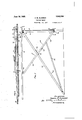
- Fig. 1 is a side elevational View of the ironing table in set up conc'l ition;
- Fig. 2 is a longitudi-. nal sectional view showing thetable infolded condition withthe ironing. boardlowermost.
- Fig. 3 is a botton'rplan vie-w showing the table in folded condition.
- Fig. 4- is a bottom plan View showing the table as it appears 1 inset up condition.
- Fig. 5 is a fragmentary View in section on the line 5-5 of Fig. 1.
- Fig. 6 is a fragmentary view in section on the line 6-6 of Fig. 1.
- I provide an ironing board 10. to. the under side of which near the front end there is secured a metal strip 12 having ends 131 which are bent at right angles to the body portion of the strip. Angle pieces or members 16 are attached to the ends 14 by pivot pins 18 which extend through the inner portions of the angle pieces. To the outer portions of these angle pieces front legs 20 are secured'by rivets 22. It will be apparent from Figs. 1 and 3 that when the device is set up the upper ends of the legs 20 come against the lower surface of the board 10 so that the latter is firmly supported, As best shown in Fig. 3, the legs 20 are braced by a pair of cross braces 24-.
- the pivot pins 18 also extend through the front portion of a rearwardly extending support consisting of two bars 26 so that these pins serve as pivots for the bars 26 as well as for the angle pieces 16.
- the bars 26 converge rearwardly and their ends are fastened together so that they rest upon the floor at a common point when the device is set up;
- Two pairs of toggle arms 28 and 30 are hingedtogether by hinges
- the up- .per ends of the arms 28 are'attached to an intermediate portion of the board 10 by hinges 3 t and the lower. ends of the arms 36 are pivoted to the legs 20 toward the lower;ends thereof by thefollowing device as best shown in Fig. 6.
- U shaped pieces 36 are secured to legs 2-0 by rivets 38 while pivot .p'ins' a0 extend through the interme- -d iate portions of the U-shaped piecesand through the ends Of tllQiilETlS 30.
- a bent rod 12' is fastened to the jbaYs'QG and it has portions which act stops to engage the arms 28 whenjthe device isset up.
- Connectingbars 46 are pivotally attached to the lower ends of the'ha'rs 26 and to the interme diateportions of the arms 30.
- This movement by means of the connecting bars 46 causes a forward thrust to be exerted on the toggle arms 30 so that 9 these arms swing forwardly in the direction of the arrow B and the arm 28 swing forwardly in the direction of the arrow C.
- This folding operation is most conveniently performed by tipping therear of the table upwardly so that the bars 26 are lifted from the floor and then by grasping the bars 26 the folding operation is initiated as stated. the lower ends of the front legs 20 being maintained in engagement with the floor.
- the bars 26 are swung up into engagement with'the lower surface of the board 10. This operation results in bringing the parts very quickly and with small effort on the part of the operator, into the completely IEOldBChHP condition shown in Fig.
- the toggle arms 28 rest upon the board 10 and that the toggle arms 80 rest upon the arms 28.
- the legs 20 are disposed outside the toggle arms and the bars 26 are disposed inside the toggle arms.
- the bars 4:6 connect the lower ends of the bars 36 with intermediate portions of the arms 30. the table can be quickly folded and unfolded by manipulation of the bar: 26 by the operator who grasps these bars at their rear end.
- An ironing table comprising an ironing board, a pair of legs pivotally attached to the front of said board, a rearwardly extending support pivotally attached to the front of said board and occupying a downwardly inclined position when the table is set up for use, toggle arms hinged together and having the upper arm hinged to an intermediate portion of said board and the lower arm hinged to said legs near their lower ends, a stop carried by said support and adapted to engage the lower side of said toggle arms, and a cgnnecting bar pivoted at one end to the rear portion of said support and pivoted at the other end to an intermediate portion of said lower arm.
- An ironing table comprising an ironing board, a pair of legs pivotally attached to the front of said board, a rearwardly extending sup )ort pivotally attached to the front of said board and consisting of two bars converging so as to meet at their rear ends and occupying a downwardly inclined position when the table is set up for use, two pairs of toggle arms hinged together and having the upper arms hinged to an intermediate portion of said board and the lower arms hinged to said legs near their lower ends, stops carried by said bars and adapted to engage the lower sides of said toggle arms, and connecting bars pivoted at their rear ends to the rear portions of said supporting bars and pivoted at their-front ends to the intermediate portions of said lowe arms.
- Au ironing table comprising an ironing board, a transverse strip attached to the lower side of said board near its front end, said strip having ends bent therefrom at right angles, pivot pins mounted in said ends, angle members mounted on the outer ends of said pivot pins, legs attached to said angle members, a rearwardly extending support consisting of two bars mounted on the inner ends of said pivot pins, said bars converging so as to meet at their rear ends and occupying a downwardly inclined position when the table is set up for use, two pairs of toggle arms hinged together and having the upper arms hinged to an intern'iediate portion of said board and the lower arms hinged to said legs near their lower ends, stops carried by said bars adapted to engage the lower sides of said toggle arms and connecting bars pivoted at their rear ends to the rear portions of said supporting bars and pivoted at their front ends to intermediate portions of said lower arms.
Description
June 16, 1925.
K. B. OLANDER IRONING TABLE 2 Sheets-Sheet 1 Filed Sept. 28, 19:23
I N vENT'oR: KEMUEL B OLA D Y'Z .M A A TTORNE Jul-1e16, 1925.
K. B. OLANDER v IRONING TABLE Filed Sept. 23,
1925 2 Sheets-Shoat 2 INVENTOR'.
. KEMUELB. OLANDER.
A TITO RNE Y6.
fication.
Patented June 16, 1925.
" un-Iran STATES OFFICE.
I KEMunL nonsense, '01; ivrrnnnnronis, rarnnnsora.
Application filed September 28, 1923. Serial No. 665,440.
To all 407mm r 2, may] concern:
Be it known that I, KEMUEL B. Oil-Alanna, a citizen of t he United States, residing" at Minneapolis, in the county of Hennepin an d State of h liinnesota, have invented certain new and useful Improvements. in Ironing ilables, of WliICll, the following IS a specii My invention relates to ironing tables, and
an object to provide a folding ironing table e f-simple and" strong construction which can. "be readily folded into compact form, and which can be quickly unfolded in such'mianner as to firmly support the ironing board in horizontal position.
The full objects and advantages of rny invention will appear in connection with the detailed"description, andthe novel features of my inventive ic'lea will be particularly pfiinted Out in theclaims. i i
In the accompanying "drawings, Fig. 1 is a side elevational View of the ironing table in set up conc'l ition; Fig. 2 is a longitudi-. nal sectional view showing thetable infolded condition withthe ironing. boardlowermost. Fig. 3 is a botton'rplan vie-w showing the table in folded condition. Fig. 4- is a bottom plan View showing the table as it appears 1 inset up condition. Fig. 5 is a fragmentary View in section on the line 5-5 of Fig. 1. Fig. 6 is a fragmentary view in section on the line 6-6 of Fig. 1.
As shown in the drawings, I provide an ironing board 10. to. the under side of which near the front end there is secured a metal strip 12 having ends 131 which are bent at right angles to the body portion of the strip. Angle pieces or members 16 are attached to the ends 14 by pivot pins 18 which extend through the inner portions of the angle pieces. To the outer portions of these angle pieces front legs 20 are secured'by rivets 22. It will be apparent from Figs. 1 and 3 that when the device is set up the upper ends of the legs 20 come against the lower surface of the board 10 so that the latter is firmly supported, As best shown in Fig. 3, the legs 20 are braced by a pair of cross braces 24-. The pivot pins 18 also extend through the front portion of a rearwardly extending support consisting of two bars 26 so that these pins serve as pivots for the bars 26 as well as for the angle pieces 16. The bars 26 converge rearwardly and their ends are fastened together so that they rest upon the floor at a common point when the device is set up; Two pairs of toggle arms 28 and 30 are hingedtogether by hinges The up- .per ends of the arms 28 are'attached to an intermediate portion of the board 10 by hinges 3 t and the lower. ends of the arms 36 are pivoted to the legs 20 toward the lower;ends thereof by thefollowing device as best shown in Fig. 6. U shaped pieces 36 are secured to legs 2-0 by rivets 38 while pivot .p'ins' a0 extend through the interme- -d iate portions of the U-shaped piecesand through the ends Of tllQiilETlS 30. A bent rod 12'is fastened to the jbaYs'QG and it has portions which act stops to engage the arms 28 whenjthe device isset up. Connectingbars 46 are pivotally attached to the lower ends of the'ha'rs 26 and to the interme diateportions of the arms 30. V
The operation and advantages of any invention will now be obviouslvhen the device 'isin the setup position shown in Fig. 1, the pairs of toggle arms QS and 30 are in alinement and-the device is-supported by the two front-legs 20 and the rear ends of the bars-26' resting upon "the floor." The device is- "firmlysupported due to the fact that the stops as carriedby the bars 26 are engaged with the upper :toggle arms 28 "while the lowerends of the bars26 are connected by the bars 46 with the toggle arms 30. The table is therefore firmly braced and supported since the rear thereof can be depressed only in case the front end is at the same time lifted. In order to fold the device, it is necessary to initiate the folding operation by moving the bars 26 in the direction of the arrow A. This movement by means of the connecting bars 46 causes a forward thrust to be exerted on the toggle arms 30 so that 9 these arms swing forwardly in the direction of the arrow B and the arm 28 swing forwardly in the direction of the arrow C. This folding operation is most conveniently performed by tipping therear of the table upwardly so that the bars 26 are lifted from the floor and then by grasping the bars 26 the folding operation is initiated as stated. the lower ends of the front legs 20 being maintained in engagement with the floor. As soon as the toggle arms have passed their dead centers, the bars 26 are swung up into engagement with'the lower surface of the board 10. This operation results in bringing the parts very quickly and with small effort on the part of the operator, into the completely IEOldBChHP condition shown in Fig. 2 so that the device may be readily stored as well as being placed in condition for shipping. By referring to this figure, it will be seen that the toggle arms 28 rest upon the board 10 and that the toggle arms 80 rest upon the arms 28. The legs 20 are disposed outside the toggle arms and the bars 26 are disposed inside the toggle arms. On account of the fact that the bars 4:6 connect the lower ends of the bars 36 with intermediate portions of the arms 30. the table can be quickly folded and unfolded by manipulation of the bar: 26 by the operator who grasps these bars at their rear end.
I claim:
1. An ironing table comprising an ironing board, a pair of legs pivotally attached to the front of said board, a rearwardly extending support pivotally attached to the front of said board and occupying a downwardly inclined position when the table is set up for use, toggle arms hinged together and having the upper arm hinged to an intermediate portion of said board and the lower arm hinged to said legs near their lower ends, a stop carried by said support and adapted to engage the lower side of said toggle arms, and a cgnnecting bar pivoted at one end to the rear portion of said support and pivoted at the other end to an intermediate portion of said lower arm.
2. An ironing table comprising an ironing board, a pair of legs pivotally attached to the front of said board, a rearwardly extending sup )ort pivotally attached to the front of said board and consisting of two bars converging so as to meet at their rear ends and occupying a downwardly inclined position when the table is set up for use, two pairs of toggle arms hinged together and having the upper arms hinged to an intermediate portion of said board and the lower arms hinged to said legs near their lower ends, stops carried by said bars and adapted to engage the lower sides of said toggle arms, and connecting bars pivoted at their rear ends to the rear portions of said supporting bars and pivoted at their-front ends to the intermediate portions of said lowe arms.
3. Au ironing table comprising an ironing board, a transverse strip attached to the lower side of said board near its front end, said strip having ends bent therefrom at right angles, pivot pins mounted in said ends, angle members mounted on the outer ends of said pivot pins, legs attached to said angle members, a rearwardly extending support consisting of two bars mounted on the inner ends of said pivot pins, said bars converging so as to meet at their rear ends and occupying a downwardly inclined position when the table is set up for use, two pairs of toggle arms hinged together and having the upper arms hinged to an intern'iediate portion of said board and the lower arms hinged to said legs near their lower ends, stops carried by said bars adapted to engage the lower sides of said toggle arms and connecting bars pivoted at their rear ends to the rear portions of said supporting bars and pivoted at their front ends to intermediate portions of said lower arms.
In testimony whereof I hereunto aflix my signature.
KEMUEL B OLANDER.
Priority Applications (1)
| Application Number | Priority Date | Filing Date | Title |
|---|---|---|---|
| US665440A US1542084A (en) | 1923-09-28 | 1923-09-28 | Ironing table |
Applications Claiming Priority (1)
| Application Number | Priority Date | Filing Date | Title |
|---|---|---|---|
| US665440A US1542084A (en) | 1923-09-28 | 1923-09-28 | Ironing table |
Publications (1)
| Publication Number | Publication Date |
|---|---|
| US1542084A true US1542084A (en) | 1925-06-16 |
Family
ID=24670117
Family Applications (1)
| Application Number | Title | Priority Date | Filing Date |
|---|---|---|---|
| US665440A Expired - Lifetime US1542084A (en) | 1923-09-28 | 1923-09-28 | Ironing table |
Country Status (1)
| Country | Link |
|---|---|
| US (1) | US1542084A (en) |
-
1923
- 1923-09-28 US US665440A patent/US1542084A/en not_active Expired - Lifetime
Similar Documents
| Publication | Publication Date | Title |
|---|---|---|
| US1542084A (en) | Ironing table | |
| US2447391A (en) | Laterally folding chair with tray | |
| US2566668A (en) | Adjustable height ironing table | |
| US2436647A (en) | Laundry cart | |
| US2618314A (en) | Combination seat, table, and benches | |
| US1675883A (en) | Bed davenport | |
| US827966A (en) | Wheeled support for ironing-stands and the like. | |
| US1814828A (en) | Folding bed | |
| US1727115A (en) | Folding chair | |
| US1468817A (en) | Combined chair and ironing board | |
| US533505A (en) | Barrel-support | |
| US1579130A (en) | Rest chair | |
| US1004955A (en) | Folding chair. | |
| US965548A (en) | Ironing-board. | |
| US1307420A (en) | Combined chaib and irontng-boabd | |
| US1976422A (en) | Stand for ironing boards and the like | |
| US2187593A (en) | Ironing table | |
| US144869A (en) | Improvement in ironing-tables | |
| US1556172A (en) | Table and the like | |
| US1035976A (en) | Collapsible go-cart. | |
| US1285881A (en) | Collapsible type-writer stand. | |
| US2229154A (en) | Folding chair | |
| US2057752A (en) | Ironing board | |
| US1250755A (en) | Combined chair and ironing-table. | |
| US1608950A (en) | Ironing table |