US1515754A - Buttonhole-sewing machine - Google Patents
Buttonhole-sewing machine Download PDFInfo
- Publication number
- US1515754A US1515754A US710317A US71031724A US1515754A US 1515754 A US1515754 A US 1515754A US 710317 A US710317 A US 710317A US 71031724 A US71031724 A US 71031724A US 1515754 A US1515754 A US 1515754A
- Authority
- US
- United States
- Prior art keywords
- buttonhole
- cam
- arm
- pawl
- eye
- Prior art date
- Legal status (The legal status is an assumption and is not a legal conclusion. Google has not performed a legal analysis and makes no representation as to the accuracy of the status listed.)
- Expired - Lifetime
Links
- 238000009958 sewing Methods 0.000 title description 11
- 230000010355 oscillation Effects 0.000 description 5
- 238000010276 construction Methods 0.000 description 3
- 230000003534 oscillatory effect Effects 0.000 description 3
- 230000015572 biosynthetic process Effects 0.000 description 2
- 238000005755 formation reaction Methods 0.000 description 2
- 239000011435 rock Substances 0.000 description 2
- 206010003402 Arthropod sting Diseases 0.000 description 1
- CVXBEEMKQHEXEN-UHFFFAOYSA-N carbaryl Chemical compound C1=CC=C2C(OC(=O)NC)=CC=CC2=C1 CVXBEEMKQHEXEN-UHFFFAOYSA-N 0.000 description 1
- 244000221110 common millet Species 0.000 description 1
- 230000004048 modification Effects 0.000 description 1
- 238000012986 modification Methods 0.000 description 1
Images

Classifications
-
- D—TEXTILES; PAPER
- D05—SEWING; EMBROIDERING; TUFTING
- D05B—SEWING
- D05B3/00—Sewing apparatus or machines with mechanism for lateral movement of the needle or the work or both for making ornamental pattern seams, for sewing buttonholes, for reinforcing openings, or for fastening articles, e.g. buttons, by sewing
- D05B3/06—Sewing apparatus or machines with mechanism for lateral movement of the needle or the work or both for making ornamental pattern seams, for sewing buttonholes, for reinforcing openings, or for fastening articles, e.g. buttons, by sewing for sewing buttonholes
- D05B3/08—Sewing apparatus or machines with mechanism for lateral movement of the needle or the work or both for making ornamental pattern seams, for sewing buttonholes, for reinforcing openings, or for fastening articles, e.g. buttons, by sewing for sewing buttonholes for buttonholes with eyelet ends
-
- D—TEXTILES; PAPER
- D05—SEWING; EMBROIDERING; TUFTING
- D05B—SEWING
- D05B73/00—Casings
- D05B73/04—Lower casings
- D05B73/12—Slides; Needle plates
Definitions
- This invention relates to buttonhole sewing machines of that type which comprise stitch-forming mechanism, work-holding means, and amain cam for producing a relative feeding movementbetween the' stitchforming mechanism and work-holding means during the stitching along the side of the buttonhole and for rotating the stitchforminga mechanism about a vertical axis thereby to form an eye at one end of the buttonhole.
- the invention relates particularly to the means for operating the main cam and one of the objects of the invention is to provide A a novel mechanism which is well adapted for high speed/operation.
- Another object of the invention is to provide a novel means by which the feed of the cam may be varied at the time that the stitching is being performed around the eye end of the buttonhole thereby to provide for making a greater or less number of stitches at the eye end.
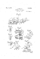
- lEig. 1 is a side view of a buttonhole sewin machine having my improvements applied thereto with the vdriving pulley removed;
- Fig. 2 is a fragmentary plan view of the mechanism for feeding the main cam
- Fig. 3 is a section on the line 3 3, Fig. 1;
- Fig. 4 is a section on the line 4 4, Fig. 1;
- Figs. 5 and 6 are views showing diderent types of buttonholes that may be formed with m present improvements
- Fig. is a fragmentary view showing the operation of the cam track and lever 31;
- Figs. 8 and 9 are modifications.
- the rlhe work-holding means by which the work is held during the stitching of the buttonhole comprises the usual work clamps 1 which are adapted to clamp the work against a work-supporting plate 2, these parts being mounted on a bed plate 3.
- the stitch-forming mechanism includes a needle 4 operating from above the work and'also suitable under thread manipulating mechchanism (not shown) which operates beneath the work and by which the upper and under threads are concatinated in the usual manner.
- the needle is carried by the usual needle bar 5 which reciprocates vertically in a head 6.
- the stitch-forming mechanism and workholding means are capable of a relative feeding movement for the forma-tion of Stitches along the edge of the buttonhole and in the machine herein shown this relative feeding movement is secured by moving the head 6 back and forth on the bed plate 3, although in some buttonhole sewing ⁇ ma chines this relative movement is secured by moving the work-holding means back and forth on the bed plate.
- the stitch-forming mechanism in the machine herein shown is also constructed to be turned about a vertical aXis so as to form the stitches around the eye end of the buttonhole and this rotary movement is secured from a rock shaft 7 journalled. in the head 6 and having a gear sector 8 thereon which meshes with a gear 9 -associated with the needle bar holder and also having another gear sector thereon by which the turret supporting the under thread-handling mechanismis rotated.
- the relative movement between the stitchforming mechanism and the work and also the turning of the rock shaft 7 to rotate the stitch-forming mechanism about the vertical axis at the eye end of the buttonhole are derived from a main cam 1Q which issituated beneath the bed plate 3 and which is provided on its periphery with worm teeth meshing with a worm 11 on a feed shaft 12 all as usual in sewing machines of this type.
- the stitch-forming mechanism is actuated from a'driving shaft 13 which is driven from a suitable pulley shown at dotted lines 14, a clutch being provided for clutching it to and unclutching it from the drive shaft as usual.
- a pawl-and-ratchet device for rotating the shaft 12, said ratchet device being 'operated from the drive shaft 13.
- the paWl-and-ratchet mechanism for actuating the shaft 12 comprises the vusual ratchet 15 fast on said shaft 12 and springpressed pawls 16 carried in an oscillating pawl carrier 17 which is mounted on the I shaft 12.
- This pawl carrier is connected by a link 18 with an arm 19 of'anoscillating member 20 that ismounted to oscillate on a hub 21 carried by the head or frame 6.
- This around the p eye oscillating member is formed with a forked portion 22, the arms of which embrace a cam 23 fast on the drive shaft 13. Rotation of the cam 23 operates through the fork 22 to oscillate the member 2O about the boss 21, such oscillating movement of the member 20 operating through the arm 19 and link 18 to actuate the pawl carrier 17 thereby to feed the shaft 12.
- the member 20 is in the nature of an elbow lever, one arm of which has the fork embracing the cam 23 and the other arm of which is connected to the pawl carrier through the link 18. This construction is conducive to high speed operation without undue jar or vibration.
- the connection between the link 18 and the pawl carrier 17 is preferably an adjustable one for which purpose the pawl carrier is formed with a slotted arm 24 in the slot 25 of which is adjustably mounted a block'26 to which the lower end ofy the link 18 is pivoted.
- My present invention relates to novel means by which this spacing of the stitches around the eye of the buttonhole is controlled. This is done by shifting automatically the pivotal connection oetween the link 18 and the arm 19 at the time that the stitching aro-und the end of the buttonhole is being performed. If this pivotal point is shifted toward the center of oscillation of the member 2O then the feeding movement of the shaft 12 and cam 1() will be slower so that a greater number of stitches can be formed while the stitch-forming mechanism is being turned about the eye of the buttonhole, while if the pivotal point is shifted away from the center of oscillation then the feeding movement of the main cam will be increased and, therefore, fewer stitches will be formed while the stitch-forming mechansm is turning about the eye of the buttonhole.
- the arm 19 is shown as having a slot 27 therein in which is slidably mounted a block 28 to which the upper end of the link 18 is pivoted.
- This block has also pivotally connected thereto one end of a link 29 that ex tends forwardly to a point in front of the driving shaft 13 and the other end of which is pivotally connected at 30 to the end of the long arm of an elbow lever 31, the short arm of said lever beingpivotally connected at 32 to a bracket 33 which is secured to the frame 6.
- the elbow of this elbow lever carries a roll 34C which rests on a track 35 secured to the bed plate 3.
- this cam surface of the track is indicated at 37 and it has such a shape and is so situated that when the stitches s are being formed around the eye end of the buttonhole the roll 34 will travel down the incline 37 thus allowing the upper end of the elbow lever 31 to swing to the left. This will move the block 28 toward the center of oscillation of the member 2O and will thus reduce the amplitude of movement of the pawl carrier due to the throw of the cam 23.
- the main cam 10 will thus be fed at a reduced speed so that an increased number of stitches will be formed during the time that the stitch forming mechanism is turning around the end of the buttonhole. This will produce a button- -hole of the type shown in Fig. 5.
- the cam face of the track 35 is in the nature of a rise as shown at 38 in Fig. 8 then during the stitching -around the eye end of the buttonhole l the roll 34 will be lifted by the rise 38 thus throwing the upperend of the elbow lever 31 to the right Fig. 1 and shifting the block 28 away from the center of oscillation. This will give the pawl carrier an increased amplitude of movement so that the turning movement of the stitch-forming mechanism will be at a greater speed with the result that fewer stitches will be formed at the eye end of the buttonhole as shown in Fig. 6.
- llt is also possible to use the incline 37 vto produce both types of buttonholes shown in Figs. 5 and 6 by extending the short end of the elbow lever 31 beyond the pivot 32 as shown at 39 and by placing the roll 34 either at the point shown in Fig. 1 of the drawings or on the end 39 as shown in Fig. 9.
- the invention also comprises means by which the spacing of the stiches 40 along the sides of the buttonhole can be varied.
- 'lhe bracket 33 is shown as provided with a hub 41 which is mounted on the boss, 21 and means are provided for adjusting the position of this bracket about the boss.
- 'llhe head 6 of the machine is provided with an larm 42 carrying a stop screw 43 which is adapted to engage the bracket 'arm 33 and by which the position of said arm is determined.
- 'llhis bracket arm v33 ' is locked in its adjusted position by means of a set screw 44. llf it is desired to in- ⁇ crease the feeding movement so that the stitches 40 along the sides of the buttonlhole will be more widely separated the stop screw 43 may be adjusted downwardly thereby swinging the bracket arm 33 downwardly.
- ⁇ movement of the stop screw 43 will result in a reverse operation.
- ⁇ 'llhis stop screw 43 provides an adjustment which augments the adjustable connection between the link 18 and the arm 24.
- the combination with stitch-forming mechanism and work-holding means movable relative to each other, said stitch-forming mechanism being rotatable about a vertical axis at the end of the buttonhole thereby to form an eye, of a cam for producing such relative movement, a feed pawl foir feeding the cam, an oscillatory pawl-actuating member having a fixed amplitude of movement, adjustable connections between said member and the pawl, the adjustment of which varies the cam-feeding movement of said pawl, a cam track, a pivoted elbow lever having one arm connected to said adjustable connections, and a roll carried by said elbow lever and operating on said track, said cam track having a cam portion with which the roll engages while the stitchforming mechanism is turning about the eye each other, said stitch-forming.
- a cam for producing such relative .movement, a feed pawl for advancing the cam, an oscillatory pawl-actuating member havinga fixed amplitude of movement and having a horizontally-extending slotted arm, a link for actuating the pawl adjustably connected to said slotted arm, a cam track,
- an elbow lever having its short arm pivotally mounted.v and its long arm connected to theadjustable connection, and a roll carried by said lever and operating on the 4. 1n a buttonhole sewing machine, the
- stitch-forming meelianisrn4 and work-holding mea-ns movable relative to each other a cam for producing such relative movement, a feed pawl for actuating the cam, an osvcillatory member pivoted on said boss and Connected to said pawl, a bracket arm acljustably secured to said boss, an elbow lever pivotecl to said bracket arm, and connected to the connection between ⁇ the oscillatory member and pawl, and a cam track for controlling the position of the elbow lever during the relative .movement between the stitch-forming mechanism and work-hold* ing means.
Landscapes
- Engineering & Computer Science (AREA)
- Textile Engineering (AREA)
- Sewing Machines And Sewing (AREA)
Description
LMS,
www.. l HQZL J. P. RTCHlE BUT'LONHOLE SEWING MACHINE :flied may 1, 1924 2 Shmmts-Shet l Fgnvenhr. y domes Ric ne byyw@ Nm'. 118, W24.. 1,515,754
. J. P. RITCHUE BUTTONHOLE SEWING MACHINE r'lled May l, 1924 2 Shems-Sheet 2 MW- 3A 37 lnven'i'ojr. domes Ff Rcime by M lf AMES P. RITCHIE, OF AMI-IERST, NEW HAMPSHIRE, ASSIG-NOR T0 THE REECE BUTTON HOLE MACHINE COMPANY, 0F BOSTON, MASSACHUSETTS, A CORPORATION 0F MAINE. I
Application led May 1,
To all whom it may concern.'
Be it known thatl, JAMES P. RITCHIE, a citizen of the United States, and resident of Amherst, county of Hillsborough, State of New Hampshire, have invented an lmprovement in Buttonhole-Sewing Machines, of which the following description, in connection with the accompanying drawing, is a specification, like characters on the drawing representing like parts.
This invention-relates to buttonhole sewing machines of that type which comprise stitch-forming mechanism, work-holding means, and amain cam for producing a relative feeding movementbetween the' stitchforming mechanism and work-holding means during the stitching along the side of the buttonhole and for rotating the stitchforminga mechanism about a vertical axis thereby to form an eye at one end of the buttonhole.
The invention relates particularly to the means for operating the main cam and one of the objects of the invention is to provide A a novel mechanism which is well adapted for high speed/operation.
Another object of the invention is to provide a novel means by which the feed of the cam may be varied at the time that the stitching is being performed around the eye end of the buttonhole thereby to provide for making a greater or less number of stitches at the eye end.
Other objects of the invention will be more fully hereinafter set forth in connection with the following description of the selected embodiment of my invention which is disclosed in the drawings.
lEig. 1 is a side view of a buttonhole sewin machine having my improvements applied thereto with the vdriving pulley removed;
Fig. 2 is a fragmentary plan view of the mechanism for feeding the main cam;
Fig. 3 is a section on the line 3 3, Fig. 1;
Fig. 4 is a section on the line 4 4, Fig. 1;
Figs. 5 and 6 are views showing diderent types of buttonholes that may be formed with m present improvements;
Fig. is a fragmentary view showing the operation of the cam track and lever 31;
Figs. 8 and 9 are modifications.
BUTToNHoLE-snwnie MACHINE.
1924. serial m7111317.
rlhe work-holding means by which the work is held during the stitching of the buttonhole comprises the usual work clamps 1 which are adapted to clamp the work against a work-supporting plate 2, these parts being mounted on a bed plate 3. The stitch-forming mechanism includes a needle 4 operating from above the work and'also suitable under thread manipulating mechchanism (not shown) which operates beneath the work and by which the upper and under threads are concatinated in the usual manner. The needle is carried by the usual needle bar 5 which reciprocates vertically in a head 6.
The stitch-forming mechanism and workholding means are capable of a relative feeding movement for the forma-tion of Stitches along the edge of the buttonhole and in the machine herein shown this relative feeding movement is secured by moving the head 6 back and forth on the bed plate 3, although in some buttonhole sewing \ma chines this relative movement is secured by moving the work-holding means back and forth on the bed plate.
The stitch-forming mechanism in the machine herein shown is also constructed to be turned about a vertical aXis so as to form the stitches around the eye end of the buttonhole and this rotary movement is secured from a rock shaft 7 journalled. in the head 6 and having a gear sector 8 thereon which meshes with a gear 9 -associated with the needle bar holder and also having another gear sector thereon by which the turret supporting the under thread-handling mechanismis rotated.'
The relative movement between the stitchforming mechanism and the work and also the turning of the rock shaft 7 to rotate the stitch-forming mechanism about the vertical axis at the eye end of the buttonhole are derived from a main cam 1Q which issituated beneath the bed plate 3 and which is provided on its periphery with worm teeth meshing with a worm 11 on a feed shaft 12 all as usual in sewing machines of this type. The stitch-forming mechanism is actuated from a'driving shaft 13 which is driven from a suitable pulley shown at dotted lines 14, a clutch being provided for clutching it to and unclutching it from the drive shaft as usual. In sewing machines of this type it is also usual to provide a pawl-and-ratchet device for rotating the shaft 12, said ratchet device being 'operated from the drive shaft 13.
The parts thus far described are or may be all as illustrated in United States Patent No. 1,083,896, January 6th, 1914 and No. 462,865, November 10th, 1891 and form no part of the present invention which relates to a novel mechanism for actuating the shaft 12 from the drive shaft 13, this meehanism being specially .designed to operate satisfactorily at a high speed and also being constructed so that the spacing of the stitches around the eye end of the buttonhole may be varied as desired.
The paWl-and-ratchet mechanism for actuating the shaft 12 comprises the vusual ratchet 15 fast on said shaft 12 and springpressed pawls 16 carried in an oscillating pawl carrier 17 which is mounted on the I shaft 12. This pawl carrier is connected by a link 18 with an arm 19 of'anoscillating member 20 that ismounted to oscillate on a hub 21 carried by the head or frame 6. This around the p eye oscillating member is formed with a forked portion 22, the arms of which embrace a cam 23 fast on the drive shaft 13. Rotation of the cam 23 operates through the fork 22 to oscillate the member 2O about the boss 21, such oscillating movement of the member 20 operating through the arm 19 and link 18 to actuate the pawl carrier 17 thereby to feed the shaft 12.
The member 20 is in the nature of an elbow lever, one arm of which has the fork embracing the cam 23 and the other arm of which is connected to the pawl carrier through the link 18. This construction is conducive to high speed operation without undue jar or vibration. The connection between the link 18 and the pawl carrier 17 is preferably an adjustable one for which purpose the pawl carrier is formed with a slotted arm 24 in the slot 25 of which is adjustably mounted a block'26 to which the lower end ofy the link 18 is pivoted.
In stitching buttonholes with an eye it is sometimes desirable to have the stitches laced closely together and other times it is desirable to have them more widely separated. In Figures 5 and 6 I have illustrated these two types of buttonholes. In Fig. 5 the stitches s around the eye of the buttonhole are shown as placed closely together while in Fig. 6 these stitches are shown as spaced further apart.
My present invention relates to novel means by which this spacing of the stitches around the eye of the buttonhole is controlled. This is done by shifting automatically the pivotal connection oetween the link 18 and the arm 19 at the time that the stitching aro-und the end of the buttonhole is being performed. If this pivotal point is shifted toward the center of oscillation of the member 2O then the feeding movement of the shaft 12 and cam 1() will be slower so that a greater number of stitches can be formed while the stitch-forming mechanism is being turned about the eye of the buttonhole, while if the pivotal point is shifted away from the center of oscillation then the feeding movement of the main cam will be increased and, therefore, fewer stitches will be formed while the stitch-forming mechansm is turning about the eye of the buttonhole.
For thus controlling the position of the pivotal connection between the link 18 and arm 19 I have provided the following mechanism.
The arm 19 is shown as having a slot 27 therein in which is slidably mounted a block 28 to which the upper end of the link 18 is pivoted. This block has also pivotally connected thereto one end of a link 29 that ex tends forwardly to a point in front of the driving shaft 13 and the other end of which is pivotally connected at 30 to the end of the long arm of an elbow lever 31, the short arm of said lever beingpivotally connected at 32 to a bracket 33 which is secured to the frame 6. The elbow of this elbow lever carries a roll 34C which rests on a track 35 secured to the bed plate 3.
36 indicates a spring which acts against the long arm of the elbow lever and which' tends to force the latter to the left Fig. 1 and thereby yieldingly hold the roll 34 against the track 35. This track 35 is situated so that as the head 6 moves back and forth during the formation of the buttonhole the roll will travel back and forth on the track and the track is constructed so that the portion thereof on which the roll is trav elling during the stitching around the end of the buttonhole is in the nature of a cam surface which will shift the position of the elbow lever 31 and thereby through the link 29 shift the position of the block 28 in the slot 27.
In the construction shown in Fig. 1 this cam surface of the track is indicated at 37 and it has such a shape and is so situated that when the stitches s are being formed around the eye end of the buttonhole the roll 34 will travel down the incline 37 thus allowing the upper end of the elbow lever 31 to swing to the left. This will move the block 28 toward the center of oscillation of the member 2O and will thus reduce the amplitude of movement of the pawl carrier due to the throw of the cam 23. The main cam 10 will thus be fed at a reduced speed so that an increased number of stitches will be formed during the time that the stitch forming mechanism is turning around the end of the buttonhole. This will produce a button- -hole of the type shown in Fig. 5.
llf, on the other hand, the cam face of the track 35 is in the nature of a rise as shown at 38 in Fig. 8 then during the stitching -around the eye end of the buttonhole l the roll 34 will be lifted by the rise 38 thus throwing the upperend of the elbow lever 31 to the right Fig. 1 and shifting the block 28 away from the center of oscillation. This will give the pawl carrier an increased amplitude of movement so that the turning movement of the stitch-forming mechanism will be at a greater speed with the result that fewer stitches will be formed at the eye end of the buttonhole as shown in Fig. 6.
llt is also possible to use the incline 37 vto produce both types of buttonholes shown in Figs. 5 and 6 by extending the short end of the elbow lever 31 beyond the pivot 32 as shown at 39 and by placing the roll 34 either at the point shown in Fig. 1 of the drawings or on the end 39 as shown in Fig. 9.
'llhe spring 36 is for the purpose of holding the roll 34 against the track and, therefore, when the roll is on the end 39 of the elbow lever 31 the spring 36 will have to be reversed as shown in Fig. 9." With the construction shown in Fig. .9 it will be observed that as the roll 34 travels down the incline 37 the/upper end of the elbow lever 31 will be thrown to the right thus increasing thespeed of feeding movement of the main cam with the result that the stitches around the eye of the buttonhole will be well separated.
The invention also comprises means by which the spacing of the stiches 40 along the sides of the buttonhole can be varied. 'lhe bracket 33 is shown as provided with a hub 41 which is mounted on the boss, 21 and means are provided for adjusting the position of this bracket about the boss.
'llhe head 6 of the machine is provided with an larm 42 carrying a stop screw 43 which is adapted to engage the bracket 'arm 33 and by which the position of said arm is determined. 'llhis bracket arm v33 'is locked in its adjusted position by means of a set screw 44. llf it is desired to in- `crease the feeding movement so that the stitches 40 along the sides of the buttonlhole will be more widely separated the stop screw 43 may be adjusted downwardly thereby swinging the bracket arm 33 downwardly. This will move the pivot point 32 of the elbow lever downwardly thus causing the upper end of said lever to move to the right with the result that the block 28 will be moved further from the axis of oscillation of the member 20, which .will increase the amplitude of movement of the l pawl carrier and thus increase the speed at which the cam 10 is fed.- A reverse 1 cam track.
`movement of the stop screw 43 will result in a reverse operation. `'llhis stop screw 43 provides an adjustment which augments the adjustable connection between the link 18 and the arm 24.
I claim:
1. ln a buttonhole sewing machine, tho
'ber and the pawl, the adjustment of which varies the cam-feeding movement of said pawl, a cam track, a. pivoted elbow lever having one arm connected to said adjustable connections, and a roll carried by said elbow lever and operating on said track.
2. In a buttonhole sewing machine, the combination with stitch-forming mechanism and work-holding means movable relative to each other, said stitch-forming mechanism being rotatable about a vertical axis at the end of the buttonhole thereby to form an eye, of a cam for producing such relative movement, a feed pawl foir feeding the cam, an oscillatory pawl-actuating member having a fixed amplitude of movement, adjustable connections between said member and the pawl, the adjustment of which varies the cam-feeding movement of said pawl, a cam track, a pivoted elbow lever having one arm connected to said adjustable connections, and a roll carried by said elbow lever and operating on said track, said cam track having a cam portion with which the roll engages while the stitchforming mechanism is turning about the eye each other, said stitch-forming. mechanism being rotatable about a vertical axis at the end of the buttonhole thereby to form an eye, of a cam for producing such relative .movement, a feed pawl for advancing the cam, an oscillatory pawl-actuating member havinga fixed amplitude of movement and having a horizontally-extending slotted arm, a link for actuating the pawl adjustably connected to said slotted arm, a cam track,
an elbow lever having its short arm pivotally mounted.v and its long arm connected to theadjustable connection, and a roll carried by said lever and operating on the 4. 1n a buttonhole sewing machine, the
combination with a frame having a boss, of
stitch-forming meelianisrn4 and work-holding mea-ns movable relative to each other, a cam for producing such relative movement, a feed pawl for actuating the cam, an osvcillatory member pivoted on said boss and Connected to said pawl, a bracket arm acljustably secured to said boss, an elbow lever pivotecl to said bracket arm, and connected to the connection between `the oscillatory member and pawl, and a cam track for controlling the position of the elbow lever during the relative .movement between the stitch-forming mechanism and work-hold* ing means.
In testimony whereof I have signed my name to this specification.
JAMES l?. RITCHIE.
Priority Applications (1)
| Application Number | Priority Date | Filing Date | Title |
|---|---|---|---|
| US710317A US1515754A (en) | 1924-05-01 | 1924-05-01 | Buttonhole-sewing machine |
Applications Claiming Priority (1)
| Application Number | Priority Date | Filing Date | Title |
|---|---|---|---|
| US710317A US1515754A (en) | 1924-05-01 | 1924-05-01 | Buttonhole-sewing machine |
Publications (1)
| Publication Number | Publication Date |
|---|---|
| US1515754A true US1515754A (en) | 1924-11-18 |
Family
ID=24853520
Family Applications (1)
| Application Number | Title | Priority Date | Filing Date |
|---|---|---|---|
| US710317A Expired - Lifetime US1515754A (en) | 1924-05-01 | 1924-05-01 | Buttonhole-sewing machine |
Country Status (1)
| Country | Link |
|---|---|
| US (1) | US1515754A (en) |
-
1924
- 1924-05-01 US US710317A patent/US1515754A/en not_active Expired - Lifetime
Similar Documents
| Publication | Publication Date | Title |
|---|---|---|
| GB774294A (en) | Zig-zag control device for sewing machines | |
| US2411493A (en) | Buttonhole sewing machine | |
| US1515754A (en) | Buttonhole-sewing machine | |
| US2340276A (en) | Buttonhole sewing machine | |
| US2301797A (en) | Buttonhole sewing machine | |
| US2152766A (en) | Sewing mechanism | |
| US2495069A (en) | Article attaching machine | |
| US3083657A (en) | Zigzag sewing machine with control device for producing composite enclosed-area stitch patterns | |
| US1394075A (en) | Sewing-machine | |
| US3745951A (en) | Needle driving device for sewing machines | |
| US1807577A (en) | Buttonhole sewing machine | |
| US2134417A (en) | Button sewing machine | |
| US2645192A (en) | Automatic button-clamp lifting means | |
| US2533293A (en) | Filler feeding mechanism for sewing machines | |
| US1565241A (en) | Buttonhole-sewing machine | |
| US1812327A (en) | Button sewing machine | |
| US2158199A (en) | Button sewing machine | |
| US2094030A (en) | Lockstitch shoe sewing machine | |
| US890582A (en) | Sewing-machine. | |
| US2338611A (en) | Start-and-stop mechanism for sewing machines | |
| US1267566A (en) | Sewing-machine. | |
| US3483835A (en) | Felling machine | |
| US3291082A (en) | Zigzag sewing machine | |
| US1058892A (en) | Crank hemstitch-embroidering machine. | |
| US1696438A (en) | Assig-nob |