US1515601A - Garbage receptacle - Google Patents
Garbage receptacle Download PDFInfo
- Publication number
- US1515601A US1515601A US613283A US61328323A US1515601A US 1515601 A US1515601 A US 1515601A US 613283 A US613283 A US 613283A US 61328323 A US61328323 A US 61328323A US 1515601 A US1515601 A US 1515601A
- Authority
- US
- United States
- Prior art keywords
- receptacle
- tilting
- garbage
- support
- gear wheel
- Prior art date
- Legal status (The legal status is an assumption and is not a legal conclusion. Google has not performed a legal analysis and makes no representation as to the accuracy of the status listed.)
- Expired - Lifetime
Links
Images


Classifications
-
- B—PERFORMING OPERATIONS; TRANSPORTING
- B65—CONVEYING; PACKING; STORING; HANDLING THIN OR FILAMENTARY MATERIAL
- B65F—GATHERING OR REMOVAL OF DOMESTIC OR LIKE REFUSE
- B65F1/00—Refuse receptacles; Accessories therefor
- B65F1/14—Other constructional features; Accessories
- B65F1/1468—Means for facilitating the transport of the receptacle, e.g. wheels, rolls
-
- B—PERFORMING OPERATIONS; TRANSPORTING
- B65—CONVEYING; PACKING; STORING; HANDLING THIN OR FILAMENTARY MATERIAL
- B65F—GATHERING OR REMOVAL OF DOMESTIC OR LIKE REFUSE
- B65F1/00—Refuse receptacles; Accessories therefor
- B65F1/14—Other constructional features; Accessories
- B65F1/141—Supports, racks, stands, posts or the like for holding refuse receptacles
Definitions
- UNITED s are renners H. Kil-HN, or THE UNITED sTATns ARMY.
- This invention relates to garbage or other refuse receptacles,r especially adapted for use at Army posts, to replace the old style screen covered inclosures containing a number of galvanized iron cans.; such places being breeding grounds for large numbers of flies and germs, and which are otherwise very unsanitary.
- the object being to provide a simple, durable and inexpensive receptacle, into which garbage or other refuse may be conveniently deposited.
- Afurther object being to provide a receptacle suspended in such a manner as ⁇ to be readily emptied.
- a further object being to provide a receptacle of such a form as to be conveniently and effectively cleaned.
- a rfurther object being to provide a receptcle that is normally closed, and will automatically open when thrown into its discharging position.
- a further object being to provide means whereby the receptacle may be adjusted as to heighth to enablethe discharge therefrom to fall into a container for removing same to a point of final disposition.
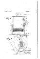
- Fig.v lis. a front view of the improved rece tacle.
- Fig. 3 is a plan view.
- Fig. 6 is a detail section of the locking means, to prevent accidental tilting of the receptacle, as shown in Fig. 5.
- l is the receptacle constructed preferably of sheet metal of about 12gaug'c, reinforced by angle-irons, to provide a light but very substantial structure the required size, for instance 750 to 800 gallons.
- the receptacle', or tank may be of .any form, but it is preferably constructed with a circular botto-m 2, thereby providing for veasy and thorough cleansing, as well as to of properly constructed uprights secured to ⁇ gether in such a manner as to firmly support the receptacle.
- wheel lll is a hand Wheel l5, provided with hand grip 16, which oliers a convenient means of operating said gear Wheel and gear Wheel 10 to tilt the receptacle.
- a spring pressed locking bolt 1T ma)7 be mounted in the housing 18, to be operated by button 19 against the tension of spring 20, to Withdraw bolt 17 from keeper 21 on the support 8, for releasing the receptacle for tilting when desired.
- the receptacle l is provided with a cover 22, a portion of Which is shown at 23, which is hinged on bar 24 mounted in brackets 25,'secured to the rigid portion 22 oi" the cover.
- Bar 24 is extended preferably beneath one side of the receptacle, and then downwardly at n?, and at its lower end is provided with a Weight 28 ot sulicient size to overbalance the Weight of the hinged portion 24 of the cover.
- the Weight 28 maintains a position vertically beneath its support, thereby retaining the portion 24 of the cover in its horiontal position, and the receptacle is tilted Without aiecting said part,-With the result that a portion of the cover, through which the contents ot the receptacle are discharged, is automatically opened When the receptacle is tilted, and is automatically closed when the receptacle is returned to its normal position.
- a portion of the cover 29 may be hinged as seen at 30, and a hand-hold 3l be provided or lifting said portion to permit the depositing of garbage into the receptacle.
- Fig. 5 is shown a portable receptacle, in every particular the same as the one described, With the exception that in this form the receptacle may be used as a collector of garbage from a number of others located This receptacle may be of the same form, mounted on Wheels 32, supporting the frame 33, the threaded shank 5 being adjusted by hand Wheel 9a.
- Bolt 17 is operated by button 19a against thetension of spring 20a in housing 18a, mounted on trame 38 to Withdraw the bolt from keeper 21a mounted on receptacle 1 to prevent its tilting.
- This device may be made in a plurality of sizes, some for permanent location adjacent to or, if desired, connected by chute with the kitchen of a mess hall, or. the like. @there may be made comparatively large and placed on Wheels, as shown in Fig. 5, for collection purposes; it being necessary only to set the receiving receptacle at such au elevation as to permit placing a portable receptacle beneath its discharge, When the contents of said receiving receptacle may be discharged in one operation into the trans porting receptacle, which may in turn be emptied in the saine expeditious and sanitary manner at the point of final disposition.
- the improved receptacle here described is designed to supersede the group of galvanized iron cans, in some instances, such as for hospitals or general messes, or large hotels and restaurants, numbering ten. or twelve cans, which are usually placed in a screened housing, that must first be opened and the. can cover removed when garbage is to be deposited. When the cans are to be emptied, the housing must be opened and 'the cans, one at a time, emptied into a cart or other transporting vehicle.
- gear Wheel mounted rigidly on the receptacle, gear Wheel mounted on the support in mesh with said Wheel on the receptacle, means for rotating the Wheel on thD support and means for raising and loW- ering the receptacle and tilting means, substantially as described.
- a closed garbage receptacle having a support of means for tiltably supporting same, comprising a supporting frame having bearings, trunnions on the receptacle adapted to rest in the bearings, means for tilting same, comprising a gear wheel mounted rigidly on the receptacle, a gear wheel mounted on the support in mesh with said wheel on the receptacle, a hand wheel secured to the gear wheel mounted on the supports for rotating same and tilting the receptacle, means 'for raising and lowering the receptacle and tilting means, comprising a threaded shank depending from the supporting means, a hand wheel threaded on the shank and secured in the supporting frame, and means for opening the receptacle when tilted, comprising a counterbalance weight attached to a portion of the cover to swing it on its hinge.
- a closed garbage receptacle having a support, means for tiltably mounting the receptacle, comprising trunnions on the receptacle adapted to rest in bearings in the support, means for tilting the receptacle, comprising a gear wheel mounted rigidly on the receptacle, a gear wheel mounted on the support in mesh with said wheel on the receptacle, means for rotating the gear on the support, means for raising and lowering the receptacle and tilting means, and means for opening the receptacle when tilted.
Description
GARBAGE RECEPTAGLE Nov. 18, QZL
3 sheets-Sheet 1 Filed dan. 17, 1923 gva/m2141501,
@ attenua/4u Nov. 18, 1924.
F'. H. KUHN GARBAGE RECEPTACLE Filed dan. 1'?. 1923 3 -SheetsnSheet 2 Patented Nov. 18, 1924.
UNITED s are renners H. Kil-HN, or THE UNITED sTATns ARMY.
1 l ernennen nncErTAoLn.
Application led January 1'?, 1923. Serial No. 613,283.
(ritmi UNDER THE AcT or MARGH a, ieee, 22 STAT. L., 625.)
To-.aZZ lwlw/m, t mamy cof/wem.'
Beit known that l, FnANors H. KUHN, lst Lieutenant, Quartermaster Corps, a citizen ,of the United States, stationed at Camp Meade, Md., have invented an Improvement in Garba ge Receptacles, of which the following is a specification.
The invention `described herein may be used by the Government, or any of its oicers or employees in prosecution of work for the Government, or by any other person in the United States, without payment of any royalty thereon.
lThis invention relates to garbage or other refuse receptacles,r especially adapted for use at Army posts, to replace the old style screen covered inclosures containing a number of galvanized iron cans.; such places being breeding grounds for large numbers of flies and germs, and which are otherwise very unsanitary.
The object being to provide a simple, durable and inexpensive receptacle, into which garbage or other refuse may be conveniently deposited.
Afurther object being to provide a receptacle suspended in such a manner as` to be readily emptied. A further object being to provide a receptacle of such a form as to be conveniently and effectively cleaned.
A rfurther object being to provide a receptcle that is normally closed, and will automatically open when thrown into its discharging position.
,A further object being to provide means whereby the receptacle may be adjusted as to heighth to enablethe discharge therefrom to fall into a container for removing same to a point of final disposition.
K Withthese and other objects inview, the invention consistsvv in the ,construction yand combination of elements herein described, and particularly pointedout in the claims.
Similar numerals indicatecorresponding parts in all the figures of the drawings in which: y
Fig.v lis. a front view of the improved rece tacle. n
ig. 2 -is a side view of same.
Fig. 3 is a plan view.
Fig. 4 is a verticalsection through the receptacle, showing sanie" in itsl tilted or discharging position. r/
desired.
' Fig. 5 is a side view, showing the receptacle mounted on wheels, in place of the stationary supports shown in other views.
Fig. 6 is a detail section of the locking means, to prevent accidental tilting of the receptacle, as shown in Fig. 5.
Reference now being had, to the drawings by numerals, l is the receptacle constructed preferably of sheet metal of about 12gaug'c, reinforced by angle-irons, to provide a light but very substantial structure the required size, for instance 750 to 800 gallons.
The receptacle', or tank, may be of .any form, but it is preferably constructed with a circular botto-m 2, thereby providing for veasy and thorough cleansing, as well as to of properly constructed uprights secured to` gether in such a manner as to firmly support the receptacle. y
Hand wheels 9 9 are threaded on shanks 5 5, and are located between the guides 6 6. By the adjustment of said hand wheels. the receptacle may beiraised or lowered as On one or bothy sides, as the weight of the receptacle demands. a tilting means is provided, said power mechanism for tilting as shown' consists of slightly extending one of the trun'nions 3 3., and mounting thereon a gear l0.
` Extending above and forming an integral v part of bearing 4 is an arm l2, at itsupper end .being provided with a ,stub shaft 13, upon which is rotatably mounted agge'ar wheel. 14 in mesh with gear 10lthe latter being keyed'to the trunnion.ofthel lreceptacle. The ratio as between gear wheels 10 and 14 may be determined by the'pow'errequired togaccomplish the tilting of the receptaclel. ,M
. Securedto, and caused to rotate withgear f at various points.
wheel lll is a hand Wheel l5, provided with hand grip 16, which oliers a convenient means of operating said gear Wheel and gear Wheel 10 to tilt the receptacle.
To prevent accidental tilting of the receptacle, a spring pressed locking bolt 1T ma)7 be mounted in the housing 18, to be operated by button 19 against the tension of spring 20, to Withdraw bolt 17 from keeper 21 on the support 8, for releasing the receptacle for tilting when desired.
The receptacle l is provided with a cover 22, a portion of Which is shown at 23, which is hinged on bar 24 mounted in brackets 25,'secured to the rigid portion 22 oi" the cover.
The hinge bar 24- is rigidly secured in brackets 26 mounted on the hinged portion 23 of the cover, to cause said hinged portion to swing open When bar 24 is rotated.
lWhen the receptacle is tilted, the Weight 28 maintains a position vertically beneath its support, thereby retaining the portion 24 of the cover in its horiontal position, and the receptacle is tilted Without aiecting said part,-With the result that a portion of the cover, through which the contents ot the receptacle are discharged, is automatically opened When the receptacle is tilted, and is automatically closed when the receptacle is returned to its normal position.
A portion of the cover 29 may be hinged as seen at 30, and a hand-hold 3l be provided or lifting said portion to permit the depositing of garbage into the receptacle.
In Fig. 5 is shown a portable receptacle, in every particular the same as the one described, With the exception that in this form the receptacle may be used as a collector of garbage from a number of others located This receptacle may be of the same form, mounted on Wheels 32, supporting the frame 33, the threaded shank 5 being adjusted by hand Wheel 9a.
Rigidly mounted on trunnion 3a of the receptacle is gear wheel a in mesh With gear 14a, operated by hand Wheel 15a for tilting the receptacle.
-Part of the cover is Weighted to automatically open, as seen, by bar 27a and Weight 28a.
This device may be made in a plurality of sizes, some for permanent location adjacent to or, if desired, connected by chute with the kitchen of a mess hall, or. the like. @there may be made comparatively large and placed on Wheels, as shown in Fig. 5, for collection purposes; it being necessary only to set the receiving receptacle at such au elevation as to permit placing a portable receptacle beneath its discharge, When the contents of said receiving receptacle may be discharged in one operation into the trans porting receptacle, which may in turn be emptied in the saine expeditious and sanitary manner at the point of final disposition.
By turning steam, hot or cold Water, or other cleansing liquid into a receptacle ot `this character', it may be thoroughly cleansed. At no time Will its contents be exposed to insects, and but very little objectionable odor discharged therefrom.
The improved receptacle here described is designed to supersede the group of galvanized iron cans, in some instances, such as for hospitals or general messes, or large hotels and restaurants, numbering ten. or twelve cans, which are usually placed in a screened housing, that must first be opened and the. can cover removed when garbage is to be deposited. When the cans are to be emptied, the housing must be opened and 'the cans, one at a time, emptied into a cart or other transporting vehicle.
The screening in the old form of housing Yiery often becomes damaged, the can tops lost, or do not lit, and the cans soon become unserviceable from handling. The attendants `tail to close the screened housing and to cover the'eans, with a result that is obvious.
ln addition to the great amount of Work in handling the garbage in thel old Way, as
compared with the labor and number of' nien required by the usefof the improved receptacle here described, the entire method. ot disposition of the garbage, as here described, is'accomplished Without exposing lil() llt) the garbage. to ilies as a breeding ground,
and reduces the discharge of objectionable odors to the minimum.
Having thus described my invention, What I claim as new and `desire to secure by Letters Patent is:
l. rl`he combination with a garbage recepf tacle, of means for tiltably supporting same,
comprising a gear Wheel mounted rigidly on the receptacle, gear Wheel mounted on the support in mesh with said Wheel on the receptacle, means for rotating the Wheel on thD support and means for raising and loW- ering the receptacle and tilting means, substantially as described.
2. The combination with a closed garbage tating one of the gears to tilt the receptacle, means for raising and lowering the receptacle and tilting means, and means for opening the receptacle when tilted.
3. The combination with a closed garbage receptacle having a support, of means for tilting same, comprising a gear Wheel mounted on the support and a gear mounted on the receptacle in mesh therewith, a hand wheel secured to one of the gears to tilt the receptacle, means for raising and lowering the receptacle and tilting means, and means for automatically opening the receptacle when tilted. y
4. The combination with a closed garbage receptacle, of means for tiltably supporting same, means for tilting same, comprising a gear wheel mounted rigidly on the receptacle, a hand wheel secured to the gear wheel mounted on the support for rotating same and tilting the receptacle,power means for raising and lowering the receptacle and tilting means, and automatic means for opening the receptacle when tilted.
5. The combination with a closed garbage receptacle having a support, of means for tiltably supporting same, comprising a supporting frame having bearings, trunnions on the receptacle adapted to rest in the bearings, means for tilting same, comprising a gear wheel mounted rigidly on the receptacle, a gear wheel mounted on the support in mesh with said wheel on the receptacle, a hand wheel secured to the gear wheel mounted on the supports for rotating same and tilting the receptacle, means 'for raising and lowering the receptacle and tilting means, comprising a threaded shank depending from the supporting means, a hand wheel threaded on the shank and secured in the supporting frame, and means for opening the receptacle when tilted, comprising a counterbalance weight attached to a portion of the cover to swing it on its hinge.
6. A closed garbage receptacle having a support, means for tiltably mounting the receptacle, comprising trunnions on the receptacle adapted to rest in bearings in the support, means for tilting the receptacle, comprising a gear wheel mounted rigidly on the receptacle, a gear wheel mounted on the support in mesh with said wheel on the receptacle, means for rotating the gear on the support, means for raising and lowering the receptacle and tilting means, and means for opening the receptacle when tilted.
FRANCIS H. KUHN.
Priority Applications (1)
| Application Number | Priority Date | Filing Date | Title |
|---|---|---|---|
| US613283A US1515601A (en) | 1923-01-17 | 1923-01-17 | Garbage receptacle |
Applications Claiming Priority (1)
| Application Number | Priority Date | Filing Date | Title |
|---|---|---|---|
| US613283A US1515601A (en) | 1923-01-17 | 1923-01-17 | Garbage receptacle |
Publications (1)
| Publication Number | Publication Date |
|---|---|
| US1515601A true US1515601A (en) | 1924-11-18 |
Family
ID=24456652
Family Applications (1)
| Application Number | Title | Priority Date | Filing Date |
|---|---|---|---|
| US613283A Expired - Lifetime US1515601A (en) | 1923-01-17 | 1923-01-17 | Garbage receptacle |
Country Status (1)
| Country | Link |
|---|---|
| US (1) | US1515601A (en) |
Cited By (2)
| Publication number | Priority date | Publication date | Assignee | Title |
|---|---|---|---|---|
| US3235212A (en) * | 1963-03-05 | 1966-02-15 | Jr Bernard J Baumiller | Portable laundry basket |
| FR2565946A1 (en) * | 1984-06-14 | 1985-12-20 | Smedt Francis De | TRASH CAN |
-
1923
- 1923-01-17 US US613283A patent/US1515601A/en not_active Expired - Lifetime
Cited By (3)
| Publication number | Priority date | Publication date | Assignee | Title |
|---|---|---|---|---|
| US3235212A (en) * | 1963-03-05 | 1966-02-15 | Jr Bernard J Baumiller | Portable laundry basket |
| FR2565946A1 (en) * | 1984-06-14 | 1985-12-20 | Smedt Francis De | TRASH CAN |
| EP0170603A1 (en) * | 1984-06-14 | 1986-02-05 | Francis De Smedt | Refuse receptacle |
Similar Documents
| Publication | Publication Date | Title |
|---|---|---|
| US1013775A (en) | Receptacle for garbage and waste paper. | |
| US1281587A (en) | Waste-receptacle for domestic use. | |
| US3490642A (en) | Garbage bin | |
| US4013215A (en) | Trash disposal apparatus | |
| US3285505A (en) | Waste paper receptacle with automatic tamping means | |
| KR100966235B1 (en) | A collection container for garbage | |
| US1515601A (en) | Garbage receptacle | |
| US2802434A (en) | Garbage and trash disposer unit | |
| US4536033A (en) | Trash storing apparatus | |
| US1566545A (en) | August b | |
| US1223525A (en) | Combined garbage-can and rat-trap. | |
| US3023425A (en) | Apparatus for receiving and treating waste materials | |
| US2665098A (en) | Saniplus garbage barrel support | |
| US2233789A (en) | Garbage and waste receptacle | |
| US2154259A (en) | Water saving toilet | |
| US2255972A (en) | Garbage receptacle | |
| ZA200501205B (en) | Waste disposal mechanism | |
| US2136010A (en) | Chip conveyer | |
| US3383035A (en) | Receptacle | |
| US1898416A (en) | Bin | |
| US1608473A (en) | Combination pail and sifter | |
| US1695133A (en) | Combination sanitaby reebigebator and waste-disposal apparatus | |
| US2041038A (en) | Garbage can or like cabinet | |
| US943089A (en) | Garbage or refuse receptacle. | |
| US58400A (en) | Improvement in privies |