US1479110A - Nozzle attachment for oil guns - Google Patents
Nozzle attachment for oil guns Download PDFInfo
- Publication number
- US1479110A US1479110A US477691A US47769121A US1479110A US 1479110 A US1479110 A US 1479110A US 477691 A US477691 A US 477691A US 47769121 A US47769121 A US 47769121A US 1479110 A US1479110 A US 1479110A
- Authority
- US
- United States
- Prior art keywords
- oil
- nipple
- nozzle
- gun
- sleeve
- Prior art date
- Legal status (The legal status is an assumption and is not a legal conclusion. Google has not performed a legal analysis and makes no representation as to the accuracy of the status listed.)
- Expired - Lifetime
Links
- 210000002445 nipple Anatomy 0.000 description 20
- 239000004519 grease Substances 0.000 description 5
- YKMMLFOYDTYAGR-UHFFFAOYSA-N 1-phenyl-2-(propan-2-ylamino)pentan-1-one Chemical compound CCCC(NC(C)C)C(=O)C1=CC=CC=C1 YKMMLFOYDTYAGR-UHFFFAOYSA-N 0.000 description 2
- 238000010276 construction Methods 0.000 description 2
- 230000004048 modification Effects 0.000 description 1
- 238000012986 modification Methods 0.000 description 1
- 238000007789 sealing Methods 0.000 description 1
Images
Classifications
-
- F—MECHANICAL ENGINEERING; LIGHTING; HEATING; WEAPONS; BLASTING
- F16—ENGINEERING ELEMENTS AND UNITS; GENERAL MEASURES FOR PRODUCING AND MAINTAINING EFFECTIVE FUNCTIONING OF MACHINES OR INSTALLATIONS; THERMAL INSULATION IN GENERAL
- F16N—LUBRICATING
- F16N21/00—Conduits; Junctions; Fittings for lubrication apertures
- F16N21/04—Nozzles for connection of lubricating equipment to nipples
-
- Y—GENERAL TAGGING OF NEW TECHNOLOGICAL DEVELOPMENTS; GENERAL TAGGING OF CROSS-SECTIONAL TECHNOLOGIES SPANNING OVER SEVERAL SECTIONS OF THE IPC; TECHNICAL SUBJECTS COVERED BY FORMER USPC CROSS-REFERENCE ART COLLECTIONS [XRACs] AND DIGESTS
- Y10—TECHNICAL SUBJECTS COVERED BY FORMER USPC
- Y10S—TECHNICAL SUBJECTS COVERED BY FORMER USPC CROSS-REFERENCE ART COLLECTIONS [XRACs] AND DIGESTS
- Y10S137/00—Fluid handling
- Y10S137/901—Biased ball valves with operators
-
- Y—GENERAL TAGGING OF NEW TECHNOLOGICAL DEVELOPMENTS; GENERAL TAGGING OF CROSS-SECTIONAL TECHNOLOGIES SPANNING OVER SEVERAL SECTIONS OF THE IPC; TECHNICAL SUBJECTS COVERED BY FORMER USPC CROSS-REFERENCE ART COLLECTIONS [XRACs] AND DIGESTS
- Y10—TECHNICAL SUBJECTS COVERED BY FORMER USPC
- Y10T—TECHNICAL SUBJECTS COVERED BY FORMER US CLASSIFICATION
- Y10T137/00—Fluid handling
- Y10T137/8593—Systems
- Y10T137/87917—Flow path with serial valves and/or closures
- Y10T137/87925—Separable flow path section, valve or closure in each
- Y10T137/87941—Each valve and/or closure operated by coupling motion
- Y10T137/87949—Linear motion of flow path sections operates both
Definitions
- EEENMJD E. SKEJLF, 0F BRIDGEPRT, CONNEGTIGUT, ASSIGNOB T0 180m FMD- UCTE CORPORATION, OF AUBURN', NW YORK, A COBJPORATIRY 0F NEW FGM NOZZLE ATTACHMENT FR @JUL GUNS.
- This invention relates to a nozzle attachment for an oil gun, whereby the gun may be utilized in connection with a nipple that is not so constructed as to receive the nozzle interiorly in telesco ing relation.
- nipp es secured to the part to be lubricated have been formed with a hollow cup for receiving the nozzle of the oil gun, and with an exteriorly beveled element u standing from the bottom of the cup and aving an oil inlet which is normall closed at its lower end by a spring chec valve, and the seating ofthe nozzle within the cup automatically opened a spring check valve in the nozzle so as to admit the oil, as is shown and described in my pending application, Serial Number 412,488, tiled September 24, 1920.
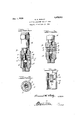
- Figure 1 is a side elevation partly in section of an oil gun equipped with the present invention
- Figure 2 is a section on line 2-2 of Figure 1;
- Figure 3 is a view similar to Figure 1, of a modied form of the invention.
- Figure 4 is a detail view in section of a further modied form.
- a sleeve 1 is provided and formed to slide at one end over the nozzle N of an oil gun G and being detachable therefrom, and at its opposite end being formed to snugly slide over the nipple A.
- a disk 2 At or 'adjacent to the center of the 1nterior of the sleeve is a disk 2 which is here shown as driven into the sleeve andl abutting a shoulder 3, though any other suitable or preferred means for' holding the disk may be resorted to if desired.
- the 'lhe disk has a central oil passa e and perforated bosses or projections 4 an 5 extendin respectively upwardly and downwardly m the opposite faces of the disk, the perforations registering with the disk opening so that a continuous oil passage 6 results.
- the projection 4 en ages and opens the valve 12 of the gun and preferably has a conical periphery so as to conformably engage in the outlet of the gun.
- the projection 5 is formed at its outer end with a square beveled countersunk portion 7 which at its outer extremity engages the ball valve 8 of the nipple A and unseats the latter so that the oil then freely passes thro h the passage 6 and countersunk portion and enters the nipple, the rojection 5 entering the nipple as shown in i e 1.
- FIG. 4 A further modification is illustrated in Figure 4, wherein the upper projection 4' is of uniform diameter and formed to unseat the gun valve as in the instance or the projection 4 of Fi l, being used in connection with guns t e mouths of the nozzles' of which are straight.
- the invention provides an attachment which can be easileand quickly a plied and removed from t and wliic can be quickl slid over nipp es of the type shown and e oil conducted directly into the nipple by the projection 5 of Figures 1 and 4 .so as to not enter the sleeve, while in Figure 3, the washer 9 acts to prevent the latter. by sealing the nipple mouth.
- An attachment for oil guns embodylng a sleeve formed at one end to be received over the nozzle of a grease gun and at its opposite end to be telescoped over a nipple, a shoulder interiorly of the sleeve, and a disk in the sleeve abutting the shoulder and having upper and lower projections the former to engage and unseat the gunrvalve and the latter to engage and unseat the n1p ple ball valve, the disk and projections having an oil passage therethrough, the lower disk being formed with a non-circular countersink to engage the ball valve.
- An attachment for oil guns embodying a sleeve formed at one end to be received over the nozzle of a grease gun and at its opposite end to be telescoped over a nipple, and a disk in the sleeve between the ends thereof and having an upper and a lower projection with an ⁇ oil passage. formed through the disk and both projections, the upper projection being formed to unseat the Lezcano gun valve and the lower projection to unseat the ball valve of the nipple.
- An attachment for oil guns embodying a sleeve formed at one end to be received over the nozzle of a grease gun and at its opposite end to be telescoped over a nipple, means in the sleeve to unseat the gun valve and means to direct oil from the unseating means into the nipple.
- An attachment for oil guns embodying a sleeve formed at one end to be received over the nozzle of a grease gun and at its opposite end to be telescoped over a nipple, and means in the sleeve to unseat the gun valve and to allow the oil to enter the nipple.
Landscapes
- Engineering & Computer Science (AREA)
- General Engineering & Computer Science (AREA)
- Mechanical Engineering (AREA)
- Nozzles (AREA)
Description
Feten elena il, l..
naar
EEENMJD E. SKEJLF, 0F BRIDGEPRT, CONNEGTIGUT, ASSIGNOB T0 180m FMD- UCTE CORPORATION, OF AUBURN', NW YORK, A COBJPORATIRY 0F NEW FGM NOZZLE ATTACHMENT FR @JUL GUNS.
Aprlioatilon lel June 155, 1921, aerial Ilo. 477,691. Renewed september il?, HWSL To all whom it may concern.'
Be it known that ll, )BERNARD l-l. SKELLY, a citizen of the United States, residing at the cit of Bridgeport, in the count of Fairfie d and State of Connecticut, ave invented certain new and useful lmprovements in Nozzle Attachments for Oil Guns; and l do declare the following to be a full, clear, and exact descri tion of the invention, such as will enab e others skilled in the art to which it appertains to make and use the same.
This invention relates to a nozzle attachment for an oil gun, whereby the gun may be utilized in connection with a nipple that is not so constructed as to receive the nozzle interiorly in telesco ing relation.
Heretofore, nipp es secured to the part to be lubricated have been formed with a hollow cup for receiving the nozzle of the oil gun, and with an exteriorly beveled element u standing from the bottom of the cup and aving an oil inlet which is normall closed at its lower end by a spring chec valve, and the seating ofthe nozzle within the cup automatically opened a spring check valve in the nozzle so as to admit the oil, as is shown and described in my pending application, Serial Number 412,488, tiled September 24, 1920.
But this construction necessitated the provision of a special form of nipple so that the nozzle of the oil gun, acting as afmale member, would enter the nipple or female member, and it is the object of the present invention to enable the nozzle of the'oil gun to be used in connection with ordinary nipples, and at the saine time to require that no change in the construction of the nozzle need be made.
ln the drawings:
Figure 1, is a side elevation partly in section of an oil gun equipped with the present invention;
Figure 2 is a section on line 2-2 of Figure 1;
Figure 3, is a view similar to Figure 1, of a modied form of the invention, and
Figure 4, is a detail view in section of a further modied form.
ln proceeding in accordance with the present invention, a sleeve 1 is provided and formed to slide at one end over the nozzle N of an oil gun G and being detachable therefrom, and at its opposite end being formed to snugly slide over the nipple A.. At or 'adjacent to the center of the 1nterior of the sleeve is a disk 2 which is here shown as driven into the sleeve andl abutting a shoulder 3, though any other suitable or preferred means for' holding the disk may be resorted to if desired. 'lhe disk has a central oil passa e and perforated bosses or projections 4 an 5 extendin respectively upwardly and downwardly m the opposite faces of the disk, the perforations registering with the disk opening so that a continuous oil passage 6 results. The projection 4 en ages and opens the valve 12 of the gun and preferably has a conical periphery so as to conformably engage in the outlet of the gun. The projection 5 is formed at its outer end with a square beveled countersunk portion 7 which at its outer extremity engages the ball valve 8 of the nipple A and unseats the latter so that the oil then freely passes thro h the passage 6 and countersunk portion and enters the nipple, the rojection 5 entering the nipple as shown in i e 1.
ln the modified form s own in Figure 3 the projection 5 is omitted, the lower or bottom face of the disk 2 being consequently flat, a ber or other washer 9 being employed which has its opening in register with the oil passage 6 so that when the sleeve l is forced over the nipple A, the washer 9 will seat on the outer end of the ni ple to form an oil seal. ln this form of t e invention, the pressure of the oil upon extruding operation of the gun is relied upon to unseat the valve 8, whereas in Fi e 1, the valve is positively held unsea `throughout the time of attachment of the oil gun to the nipple.
A further modification is illustrated in Figure 4, wherein the upper projection 4' is of uniform diameter and formed to unseat the gun valve as in the instance or the projection 4 of Fi l, being used in connection with guns t e mouths of the nozzles' of which are straight.
lin all forms of the invention it will be seen that the invention provides an attachment which can be easileand quickly a plied and removed from t and wliic can be quickl slid over nipp es of the type shown and e oil conducted directly into the nipple by the projection 5 of Figures 1 and 4 .so as to not enter the sleeve, while in Figure 3, the washer 9 acts to prevent the latter. by sealing the nipple mouth.
What is claimed 1s:
1. An attachment for oil guns embodylng a sleeve formed at one end to be received over the nozzle of a grease gun and at its opposite end to be telescoped over a nipple, a shoulder interiorly of the sleeve, and a disk in the sleeve abutting the shoulder and having upper and lower projections the former to engage and unseat the gunrvalve and the latter to engage and unseat the n1p ple ball valve, the disk and projections having an oil passage therethrough, the lower disk being formed with a non-circular countersink to engage the ball valve.
2. An attachment for oil guns embodying a sleeve formed at one end to be received over the nozzle of a grease gun and at its opposite end to be telescoped over a nipple, and a disk in the sleeve between the ends thereof and having an upper and a lower projection with an` oil passage. formed through the disk and both projections, the upper projection being formed to unseat the Lezcano gun valve and the lower projection to unseat the ball valve of the nipple.
3. An attachment for oil ns embodying a sleeve formed at one endg-io be received over the nozzle of a grease gun and at itsy opposite end to be telescoped over a nipple, and /a disk in the sleeve between the ends thereof and having an upper projection :formed to enter the gun nozzle and to unseat the valve thereof, the disk and projection having an oil passage.'
4. An attachment for oil guns embodying a sleeve formed at one end to be received over the nozzle of a grease gun and at its opposite end to be telescoped over a nipple, means in the sleeve to unseat the gun valve and means to direct oil from the unseating means into the nipple.
5. An attachment for oil guns embodying a sleeve formed at one end to be received over the nozzle of a grease gun and at its opposite end to be telescoped over a nipple, and means in the sleeve to unseat the gun valve and to allow the oil to enter the nipple.
In testimony whereof I afiix my signaturev hereto.
BERNARD EL SKELLY.
Priority Applications (1)
| Application Number | Priority Date | Filing Date | Title |
|---|---|---|---|
| US477691A US1479110A (en) | 1921-06-15 | 1921-06-15 | Nozzle attachment for oil guns |
Applications Claiming Priority (1)
| Application Number | Priority Date | Filing Date | Title |
|---|---|---|---|
| US477691A US1479110A (en) | 1921-06-15 | 1921-06-15 | Nozzle attachment for oil guns |
Publications (1)
| Publication Number | Publication Date |
|---|---|
| US1479110A true US1479110A (en) | 1924-01-01 |
Family
ID=23896946
Family Applications (1)
| Application Number | Title | Priority Date | Filing Date |
|---|---|---|---|
| US477691A Expired - Lifetime US1479110A (en) | 1921-06-15 | 1921-06-15 | Nozzle attachment for oil guns |
Country Status (1)
| Country | Link |
|---|---|
| US (1) | US1479110A (en) |
Cited By (4)
| Publication number | Priority date | Publication date | Assignee | Title |
|---|---|---|---|---|
| US2517571A (en) * | 1947-02-19 | 1950-08-08 | Jr Gotthard Janson | Valve coupling |
| US2578193A (en) * | 1949-03-01 | 1951-12-11 | Jr Walton H Marshall | Ammonia dissociator |
| US2857900A (en) * | 1955-11-25 | 1958-10-28 | California Research Corp | Starting device for internal combustion engines |
| US4558587A (en) * | 1984-08-29 | 1985-12-17 | Varian Associates, Inc. | Ball-type vacuum valve for leak detection apparatus |
-
1921
- 1921-06-15 US US477691A patent/US1479110A/en not_active Expired - Lifetime
Cited By (4)
| Publication number | Priority date | Publication date | Assignee | Title |
|---|---|---|---|---|
| US2517571A (en) * | 1947-02-19 | 1950-08-08 | Jr Gotthard Janson | Valve coupling |
| US2578193A (en) * | 1949-03-01 | 1951-12-11 | Jr Walton H Marshall | Ammonia dissociator |
| US2857900A (en) * | 1955-11-25 | 1958-10-28 | California Research Corp | Starting device for internal combustion engines |
| US4558587A (en) * | 1984-08-29 | 1985-12-17 | Varian Associates, Inc. | Ball-type vacuum valve for leak detection apparatus |
Similar Documents
| Publication | Publication Date | Title |
|---|---|---|
| US1322938A (en) | of utica | |
| US1479110A (en) | Nozzle attachment for oil guns | |
| US2137786A (en) | Spray oiler | |
| US2232359A (en) | Lubrication fitting | |
| US2344657A (en) | Valve seat construction | |
| US1991388A (en) | Spraying apparatus | |
| US2348248A (en) | Automatic valve for pressure type atomizers | |
| US1879363A (en) | Self-cleaning atomizer | |
| US2032789A (en) | Spray gun for asphalt or the like | |
| US1575755A (en) | Connection for lubricating systems | |
| US1781554A (en) | Lubricator | |
| US1393908A (en) | Quick-acting high-pressure connection | |
| US2653054A (en) | Duplex nozzle | |
| US2002630A (en) | Shampoo fixture | |
| US2096247A (en) | Hand-oiler | |
| US1782691A (en) | Grease-gun coupling head | |
| US1964575A (en) | Nozzle gas burner | |
| US2104903A (en) | Lubricator valve construction | |
| US1500702A (en) | Oil injector | |
| US1637326A (en) | Pressure lubricating system and apparatus | |
| US1622341A (en) | Combined air nozzle and gauge | |
| GB349883A (en) | Improvements in or relating to the nozzles of lubricators | |
| US2389053A (en) | Spray nozzle | |
| US1513891A (en) | Lubricator | |
| US2556051A (en) | Spray attachment for fluid containers |