US1459446A - Inturned welt-knitting machine - Google Patents
Inturned welt-knitting machine Download PDFInfo
- Publication number
- US1459446A US1459446A US320311A US32031119A US1459446A US 1459446 A US1459446 A US 1459446A US 320311 A US320311 A US 320311A US 32031119 A US32031119 A US 32031119A US 1459446 A US1459446 A US 1459446A
- Authority
- US
- United States
- Prior art keywords
- needles
- welt
- sleeve
- knitting machine
- parts
- Prior art date
- Legal status (The legal status is an assumption and is not a legal conclusion. Google has not performed a legal analysis and makes no representation as to the accuracy of the status listed.)
- Expired - Lifetime
Links
- 238000009940 knitting Methods 0.000 title description 26
- RZVAJINKPMORJF-UHFFFAOYSA-N Acetaminophen Chemical compound CC(=O)NC1=CC=C(O)C=C1 RZVAJINKPMORJF-UHFFFAOYSA-N 0.000 description 7
- 230000015572 biosynthetic process Effects 0.000 description 6
- 238000005755 formation reaction Methods 0.000 description 6
- 239000002184 metal Substances 0.000 description 5
- 241000220010 Rhode Species 0.000 description 3
- 238000010276 construction Methods 0.000 description 3
- 238000005452 bending Methods 0.000 description 2
- 230000000694 effects Effects 0.000 description 2
- 241000282472 Canis lupus familiaris Species 0.000 description 1
- 229910000831 Steel Inorganic materials 0.000 description 1
- 208000024780 Urticaria Diseases 0.000 description 1
- 238000005219 brazing Methods 0.000 description 1
- 230000003028 elevating effect Effects 0.000 description 1
- 239000004744 fabric Substances 0.000 description 1
- 238000004519 manufacturing process Methods 0.000 description 1
- 230000004048 modification Effects 0.000 description 1
- 238000012986 modification Methods 0.000 description 1
- 230000000630 rising effect Effects 0.000 description 1
- 238000007493 shaping process Methods 0.000 description 1
- 239000010959 steel Substances 0.000 description 1
Images


Classifications
-
- D—TEXTILES; PAPER
- D04—BRAIDING; LACE-MAKING; KNITTING; TRIMMINGS; NON-WOVEN FABRICS
- D04B—KNITTING
- D04B9/00—Circular knitting machines with independently-movable needles
- D04B9/06—Circular knitting machines with independently-movable needles with needle cylinder and dial for ribbed goods
Definitions
- This invention relates to knitting machines for forming turned 'w'elts integral therewith and particularly for forming inturned welts integral with the top of seamless stockings.
- Fig. 1 is a front elevation of a knitting machine having my welt forming attachment applied thereto;
- Fig. 2 is an end elevation of the mechanism shown in Fig. 1;
- Fig. 3 is'a side elevation of the so-called headof the mechanism shown in Figs. 1
- Fig. 4 is a side elevation of the said head on the broken line 1-4 of Fig. 1, viewed from the side opposite 3;
- Fig. 5 is a plan view of the head, certain parts being shown in transverse section;
- Fig. 6 is a plan view of a portion of a upon the horizontal section line 6-6 of Fig. 4:;
- Fig. 7 is a front elevation of the head, parts being broken away;
- Fig. 7 is a detail Tn vertical section of a part of the plunger mechanism controlling certain of the cams; I 4
- Fig. 8 is a vertical section of the head upon the line 8-8 of Fig. 4;
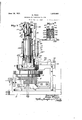
- Fig. 9 is a vertical, central section taken through the needle cylinder, the head and closely adjacent parts;
- Fig. 10 is a detail in vertical, central section of the construction shown; in the lower part of Fig. 9, but representing the parts in diiierent position from that of Fig. 9;
- Fig. 11 is a transverse sectionupon the line 11-11 of Fig. 9;
- Fig. 12 is a transverse section upon tlie line 1212 of Fig. 9;
- Figs. 13, 14 and 15 are details of the ratchet mechanism controlling the loading and transferring devices and showing the parts in different positions, said parts being viewed from the right;
- Fig. 16 is a left hand side elevation of the said ratchet mechanism and also showing the operating hand mechanism therefor;
- Fig. 17 is a plan view with certain parts in section of the operating levers shown in Fig. 2;
- Fig. 18 is a plan View ofa part ofthe a more nearly complete state of manufacture
- Fig. 24 is a side elevation of a complete jack formed by bending the blank shown in Fig. 23 upon a vertical central line;
- Fig. 25 is a .iolan'viewv of the completed jack shown in Fig. 24:;
- Fig. 26 is a front elevation representing a pair of needles and the sinkers or web holders cooperating therewith;
- Fig. 27. is a side elevation of one of said sinkers or web holders
- Figs. 28 andv 29 are respectively a plan view and a side elevation of a very slightly modified form of my invention and constituting the preferred form thereof;
- Figs. 30 and 31 are respectively a plan view and a side elevation of a still further modified form of my invention.
- Fig. 32 is a plan view representing a plurality ofjacks of still another form of my invention, in their relation to the needles;
- Fig. 33 s a side elevation of one of the jacks shown in Fig. 32;
- Fig. 34 is'a. plan view of still another 5 form of jack of my invention.
- Fig: 35 is a vertical section taken through the jack shown in Fig. 34;
- Fig. 36 is a plan view representing a jack constituting still another form of my invention and showing infull lines the jack in position for loading and new lines in position for transferring;
- Fig. 37 is a lan view of a jack constituting still another tom of my invention.
- Fi 38 is a plan view similar to Fig. 30
- Fig. 39 is a detail in sideeleva'tion representing two needles and related jacks as positioned during the loading operat on;
- Fi i0 is a similar View of the parts as positioned for the transferring operation; and I Fig. 41 is a plan view showing the modified arrangement of cams for operating the jacks for loading and for transferring.
- My invention in its preferred embodiment constitutes an attachment for a circular knittin m ification be applied to various types of circular knitting machines. It may, for example, be applied to a machine wherein the needle cylinder rotatesand the cam ring is stationary, or to a machine wherein the cam ring rotates and the needle cylinder is stationary.
- the knitting machineto which the invention is applied 18 preferably employed for knitting stmkings, though within the scope and purpose of my invention a welt may be formed upon any desired knitted article.
- my invention is employed upon a machine for knitting a seamless stocking having heel and toe pockets, though with or without modifica tion, my invention may be applied to other Wm of knitting machines.
- ile my invention may be used upon any desired or suitable type of knitting machine, I have represented it as applied to or embodied in a circular knitting machine of the so-called Banner type, one form of which is disclosed in the patent to Hemphill,- No. 933,443, September-7, 1909, to which reference may be made for a complete disclosure of parts not herein necessary to set forth in detail.
- the rotatable-needle cylinder is marked N in Fig. 9, the non-rotatable cam carrier is spectively p, p, p" (quick speed, slow speed and loose), and at 8,111 Fig. 2, is indicated the main shaft on which the said pulleys are machine, and it may with or without.
- Upon said drum or barrel 8 is preferably provided a pattern ring engagingthe clutch shifting lever whereby the clutch is shifted so as to operate by rotary or round and round knitting throughout the formation of the 1e and preferably the foot of the stocking, an by reciprocating knittin throughout the formation of the heel an toe in a manner not herein necessary more fully to describe.
- the needle cylinder rotates and reciprocates and the cam ring is stationary, though obviously and as above stated, the reverse construction and operation may be employed.
- my invention may be embodied and prac- 2 and preferably upon said block are also mounted the usual narrowing pickers 3, as shown in Flg. 2.
- the usual in-step cam At a suitable point upon the cam ring is mounted the usual in-step cam to lower all the needles and there are also preferably provided a levelling cam and widening picker mechanism, the latter here embodied in two pickers, one of which is shown at 5.
- These pickers preferably operate substantially as shown in the said Hemphill patent, but if desired a single widening picker may be employed instead and operated'in a manner not herein necessary more fully to describe.
- the knitting machine is equipped with a latch ring indicated at 6, and which is herein represented as pivoted at 7 upon a suitable standard or bracket 8 rising from the bed plate 9 of the machine.
- the machine is provided with suitable thread guides which may be and preferably are of the general type shown in the said Hemphill patent and herein for that purpose I have represented a series of thread guide levers 10, 11, 12, 13, 14 in Fig. 6, the thread lever 12 preferably-being employed to guide to the needles the thread that is employed in'knitting the top and leg of the stocking.
- The. thread lever 131113.57 be used.
- my in vention is not limited in this respect.
- the needle cylinder N is provided with suitable needles 15 (see Fig. 9) which are referably, but not necessarily, latch needles. Ely invention eculiarly cooperates with latch needles.
- suitable sinkers or' web holders 16 mounted to slide in suitable radial grooves in the sinker ring 17 surrounding the needle cylinder at the top thereof. These sinkers or web holders may be of any suitable construct1on, but preferably are of substantially the form shown in Figs. 26 and 27.
- Overlying the sinker ring 17 and the sinkers therein, 1 provide the sinker cap ring 18 having preferably usual cams for operating the sinkers.
- the mechanism to which my invention more particularly relates may be supported in any suitable manner.
- a stand or bracket 19 which is suitably formed for the reception of a post or spindle 20 fast therein and upon which is loosely mounted for sliding vertical movement a sleeve 21 integrally formed with or suitably connected to a sleeve 22.
- Bolted or otherwise suitablysecured to the post or spindle 20, as by set screws 23 is a collar 24 having an arm 25,
- a sleeve 26 which is adapted to slide upon a spindle 27 positioned in vertical parallelism with the post or spindle 20.
- the said spindle 27 is received in a socket or opening in the sleeve 22 and is made fast therein by one or more bolts 28. 1 preferably provide the spindle 27 and adjacent parts to prevent turning movement of the sleeve 24, the arm 25 and the sleeve 21.
- I provide suitable means for elevating periodically the sleeve 21 and connected parts, and for this purpose have herein represented as most clearly shown in Fig. 8, a lever 29 pivoted at 30 upon a bracket 31 secured by bolt 32 to the stand 19, one arm 33 of said lever taking under the lower end 34 of said sleeve 21, so as to impart vertical sliding movement thereto and to the parts connected therewith.
- the said lever 29 is operated in any suitable manner, as by means of a link or slide 35 pivoted thereto at 36 and at its lower end connected at 37 to a lever 38 pivoted at 39.
- Said lever 38 is provided with a head 40 adapted to be acted upon by a suitable cam 41 upon the shaft 8'.
- the head constituting the support for the instruments that cooperate with the knitting needles in the formation of the welt, as well as the support for the operating cam therefor and like parts- Referring more particularly to Figs. 3,
- the lever 46 as shown clearly in Fig. 2 is connected at its outer end to an upright link or rod, the lower end whereof is connected to a lever pivoted at 44. and which, as shown in Fig. 2 and also in Fig. 17, is adapted to be acted upon at suitable times by a cam on the shaft 8', thereby to cause said rod 42 to be raised or lowered and the dogs 62, 63 to engage the lugs 67, 68 shown in Figs. 9 and 11.
- the rod 42 at its lower end extends through the sleeve 54 of the dial 55'and below the needle cylinder N and the driving gear 56 for the latter.
- To the lower end of the rod 42 are pivoted at 57 two links 58, 59 respectively pivoted at 60, 61 to two levers 62, 63, themselves pivoted at 64 in the depending part 65 of the sleeve portion 54 of the dial 55.
- Preferably the lower part of the sleeve 54 is cut away or recessed as indicated at 66 in Fig. 10.
- the driving gear 56 for the needle cylinder is provided with two diametrically opposite lugs 67. 68 shown most clearly in Fig. 9, and which, as indicated at 69 in Fig. 4. are both bevelled or tapered upon those faces thereof that are adapted to be engaged by the levers 62,, 63.
- the upper surface of the dial 55 is provided with grooves 70 in which are mounted the instruments, various forms whereof are shown in Figs. 22 to 37 inclusive.
- Fi I Fi .22, I have indicated at 72 a blank from w ich one form of my ads or transferrer may be constructed; blank is preferably feed of highly resilient sheet .when it is folded into the substantially of an ellipse.
- metal such as steel
- This blank as stamped out, is provided with one or two butts 73, 74 and with curved ends 75, 76.
- the instrument then has the form shown in Fig.
- the points 77, 78 are essentially parallel with each other, and particularly do they touch at their outer ends 81, 82, as clearly indicated in F ig. 25.
- the 0&- set portions 79, 80' of the instrument form the. eye, such eye being of substantially curved form, as shown in Fig. 25, wherein the curve is represented as taking the form
- the offset portion constituting the eye of the instrument does not include any portion of the points 77, 78, as is clearly evident from Fig. 25.
- Each of the points 77, 78 is preferably curved at its upper and lower edges, and such hooks are of reduced or slight vertical extentcompared with the vertical extent of the body of the instrument, as is evident from Figs. 23 and 24.
- FIGs. 28 and 29 I have represented another form of instrument constituting a jack or transferrer. Such instrument is preferably formed by the same operatlons that I have described at length with respect to Figs. 22 to 25.
- the points 83, 84 are in I out the blank in such man forward end of said points or hooks. 83, 84.
- the instrument shown in this form of m invention is preferabl formed from a bla that is doubled at midlength in a manner similar to that described ,with reference to course in question is integrally united with the wales of the body web.
- That form of my invention shown in Fi s. 32 and 33 differs from that shown in igs. and 31 in that each jack is provided with three hooks 8 8, 89, 90, each preferably having the form in side elevatlon shown in Fig. 33.
- each of these jacks is formed from a sheet of metal folded midlength upon itself at 9 1 and between the members 92, 93 is inserted a piece 94 that may be secured by a rivet, brazing or otherwise to the members 92, 93.
- the piece 94 is provided with a hook 89 similar to the hooks 88, 90, and when the implements are projected as indicated in Fig. 32, the needles 91 have the relation thereto indicated in said figure. It will thus be evident that as many loops are provided upon the total number of hooks 88, 89, 90 as there are needles 91, the result being that all the loops or stitches of acourse of the inturned portion of the welt are integrally united with wales of the body web.
- the instrument is composed of a member 94' having a thin under edge 95 and a preferably flat and relatively thick upper edge 96, the member being preferably wedge shaped in vertical section.
- the member is vertically recessed as indicated at 97 for the passage of the needle to which the loop is to be transferred in completing the welt and the forward end of the member terminates in a hook 98, which may be upturned like the hook shown in Figs. 24, 29, 31 and 33.
- the instrument is preferably composed of a blank bent upon itself at99 to provide the two members 100 and 101 occupying a face to face relation in substantial contact as shown in Fig. 25.
- Each of said members is oflset at 102, 103, to form an eye 104, and in addition the eye together with thehooks 105, 106 are bent at an angle 'which is preferably seven degrees with respect to the direction of the members 100, 101.
- the groove 107 in the dial is not radial, but is" at an angle of substantially seven degrees to a radius.
- Fig. 37 l have shown still another form of my invention, wherein the instrument comprises a body portion 109 with a bend or ofi'set 110 near the front end, and in advance of which is a hook 111 that in side elevation is preferably of the same form as the hook shown in Figs. 24, 31, 33.
- each sinker which may be of a general form indicated at 112 in Fig. 27, with one or a plurality of lateral formations 113 of ridge-like character.
- formations may be provided by corru ating or similarly shaping the sinkers or we holders 27 when stamping them out or as a subsequent step in the operation.
- Thesaid formations 113 are of relatively slight de th and may be either horizontal or somew at inclined. They should, however, be so positioned as to engage the needles and preferably both as they rise and as they descend,
Landscapes
- Engineering & Computer Science (AREA)
- Textile Engineering (AREA)
- Knitting Machines (AREA)
Description
June 19, 1923. 1,459,446 R. FENN INTURNED WELT KNITTING MACHINE Filed Aug. 27 1919 15 Sheets-Sheet 'lnveniov:
June 19, 1923..
R. FENN v INTURNED WELT KNITTING MACHINE Sheet 2 Filed Aug. 2'? 1919 15 Sheets- June 19 1923. 1,459,446
I R. FENN iNTURNED WELT KNITTING MACHINE Filgd Aug. 27, 1919 15 Sheets-Sheet 5 3 y Fawn,
June w, 1923. 1,459,446 R. FENN 'INTURNED WELT KNITTING MACHINE Filed Aug. 27 1919 15 Shets-Sheet 4 R. FENN INTURNED WELT KNITTING MACHINE Filed Aug. 27. 1919- 15 Sheets -She et 5 June 19, 1923. 1,459,446
. R. FENN INTURNED WELT KNITTING MACHINE Filed Aug. 27. 1919 15 Sheets-Sheet s Invenior: .r 1 22mm,
June 19, 1923. 1,459,446
R. FENN I INTURNED WELT KNITTING MACHINE Filed Auz. 27, 1919 I -15 Sheets-Sheet '7 June 19, 1923.
Filed Aug. 27 {1919 I nvenifor Iii-nay,
62;? 3% ww w z/ R. FENN INTURNED WELT KNITTING MACHINE Jun w, 1923. 1,459,446
Filed AuE. 2 7 1919 15 Sheets-Sheet 15 fl; EQ I I /a/ R. FENN INTURNED WELT KNITTING MACHINE June 19, 1923. 1,459,446
Filed Aug. 27, 1919 15 Sheets-Sheet 14 June-19, 1923. M55926 R. FENN V INTURNED WELT KNITTING MACHINE Filed Auk. 2'7, 1919 15 Sheets-Sheet 15 Emwm%0 T y Fmm wiw zwyw head but viewed 55' nits BAY FENN, OF PROVIDENCE, RHODE ISLAND, ASSIGNOB TO HEMPHILL com, OF CENTBM FALLS, RHODE ISLAND, A CORPORATION OF MAssAcfiUsET Ts'.
INTUBNED WELT-KNITTING- MACHINE.
Application filed August 27, 1919. Serial No. 320,311.
To all whom it may concern:
Be it known that I, RAY FENN, a citizen of the United States, and a resident of Providence, in the county of Providence and State of Rhode Island, have invented an Improvement in Inturned-Welt-Knitting Machines, of which the following description, in connection with the accompanying drawings, is a specification, like characters on the drawings representing like parts.
This invention relates to knitting machines for forming turned 'w'elts integral therewith and particularly for forming inturned welts integral with the top of seamless stockings.
In order that the invention may be clearly understood, 1 have disclosed a single type or embodiment thereof in the accompanying drawings, wherein- Fig. 1 is a front elevation of a knitting machine having my welt forming attachment applied thereto;
Fig. 2 is an end elevation of the mechanism shown in Fig. 1;
Fig. 3 is'a side elevation of the so-called headof the mechanism shown in Figs. 1
and 2;
' Fig. 4: is a side elevation of the said head on the broken line 1-4 of Fig. 1, viewed from the side opposite 3;
Fig. 5 is a plan view of the head, certain parts being shown in transverse section;
Fig. 6 is a plan view of a portion of a upon the horizontal section line 6-6 of Fig. 4:;
Fig. 7 is a front elevation of the head, parts being broken away;
Fig. 7 is a detail Tn vertical section of a part of the plunger mechanism controlling certain of the cams; I 4
Fig. 8 is a vertical section of the head upon the line 8-8 of Fig. 4;
Fig. 9 is a vertical, central section taken through the needle cylinder, the head and closely adjacent parts;
Fig. 10 is a detail in vertical, central section of the construction shown; in the lower part of Fig. 9, but representing the parts in diiierent position from that of Fig. 9;
Fig. 11 is a transverse sectionupon the line 11-11 of Fig. 9;
Fig. 12 is a transverse section upon tlie line 1212 of Fig. 9;
Figs. 13, 14 and 15 are details of the ratchet mechanism controlling the loading and transferring devices and showing the parts in different positions, said parts being viewed from the right;
Fig. 16 is a left hand side elevation of the said ratchet mechanism and also showing the operating hand mechanism therefor;
Fig. 17 is a plan view with certain parts in section of the operating levers shown in Fig. 2;
Fig. 18 is a plan View ofa part ofthe a more nearly complete state of manufacture;
Fig. 24 is a side elevation of a complete jack formed by bending the blank shown in Fig. 23 upon a vertical central line;
Fig. 24: is a similar view of a slightly modified form of. jack, embodying my in= vention;
Fig. 25 is a .iolan'viewv of the completed jack shown in Fig. 24:;
Fig. 26 is a front elevation representing a pair of needles and the sinkers or web holders cooperating therewith;
Fig. 27. is a side elevation of one of said sinkers or web holders;
Figs. 28 andv 29 are respectively a plan view and a side elevation of a very slightly modified form of my invention and constituting the preferred form thereof;
Figs. 30 and 31 are respectively a plan view and a side elevation of a still further modified form of my invention;
Fig. 32 is a plan view representing a plurality ofjacks of still another form of my invention, in their relation to the needles;
Fig. 33 s a side elevation of one of the jacks shown in Fig. 32;
Fig. 34 is'a. plan view of still another 5 form of jack of my invention;
Fig: 35 is a vertical section taken through the jack shown in Fig. 34;
Fig. 36 is a plan view representing a jack constituting still another form of my invention and showing infull lines the jack in position for loading and new lines in position for transferring;
Fig. 37 is a lan view of a jack constituting still another tom of my invention. Fi 38 is a plan view similar to Fig. 30
of still another form'of my invention;
Fig. 39 is a detail in sideeleva'tion representing two needles and related jacks as positioned during the loading operat on;
Fi i0 is a similar View of the parts as positioned for the transferring operation; and I Fig. 41 is a plan view showing the modified arrangement of cams for operating the jacks for loading and for transferring.
My invention in its preferred embodiment constitutes an attachment for a circular knittin m ification be applied to various types of circular knitting machines. It may, for example, be applied to a machine wherein the needle cylinder rotatesand the cam ring is stationary, or to a machine wherein the cam ring rotates and the needle cylinder is stationary. The knitting machineto which the invention is applied 18 preferably employed for knitting stmkings, though within the scope and purpose of my invention a welt may be formed upon any desired knitted article. Preferably, however, my invention is employed upon a machine for knitting a seamless stocking having heel and toe pockets, though with or without modifica tion, my invention may be applied to other Wm of knitting machines.
ile my invention may be used upon any desired or suitable type of knitting machine, I have represented it as applied to or embodied in a circular knitting machine of the so-called Banner type, one form of which is disclosed in the patent to Hemphill,- No. 933,443, September-7, 1909, to which reference may be made for a complete disclosure of parts not herein necessary to set forth in detail.
I shall proceed to describe my invention as applied to a machine of the Banner type, but it is to be understood that such specific description is in no sense a limitation uponthe.
scope of the invention.
In as much as certain general parts of the mechanism herein shown may beand preferably are the same as those shown inthe said patent to Hemphill, No. 933,443, I have designated such'parts b the same reference characters that are emp oyed in the said patient. 'lhus the machine frame is marked a,
the rotatable-needle cylinder is marked N in Fig. 9, the non-rotatable cam carrier is spectively p, p, p" (quick speed, slow speed and loose), and at 8,111 Fig. 2, is indicated the main shaft on which the said pulleys are machine, and it may with or without.
marked H, and the annular portion or ledge" mounted. The pattern shaft is indicated in Fig. 2 at s, f and shown in Fig.'--=1 being the pattern or cam rumor barrels upon the said shaft. Upon said drum or barrel 8 is preferably provideda pattern ring engagingthe clutch shifting lever whereby the clutch is shifted so as to operate by rotary or round and round knitting throughout the formation of the 1e and preferably the foot of the stocking, an by reciprocating knittin throughout the formation of the heel an toe in a manner not herein necessary more fully to describe. In the disclosed application or embodiment of my invention, the needle cylinder rotates and reciprocates and the cam ring is stationary, though obviously and as above stated, the reverse construction and operation may be employed. Moreover my invention may be embodied and prac- 2 and preferably upon said block are also mounted the usual narrowing pickers 3, as shown in Flg. 2. At a suitable point upon the cam ring is mounted the usual in-step cam to lower all the needles and there are also preferably provided a levelling cam and widening picker mechanism, the latter here embodied in two pickers, one of which is shown at 5. These pickers preferably operate substantially as shown in the said Hemphill patent, but if desired a single widening picker may be employed instead and operated'in a manner not herein necessary more fully to describe.
Preferably and as indicated in Figs. 1, 5, 7, 9, etc., the knitting machine is equipped with a latch ring indicated at 6, and which is herein represented as pivoted at 7 upon a suitable standard or bracket 8 rising from the bed plate 9 of the machine. The machine is provided with suitable thread guides which may be and preferably are of the general type shown in the said Hemphill patent and herein for that purpose I have represented a series of thread guide levers 10, 11, 12, 13, 14 in Fig. 6, the thread lever 12 preferably-being employed to guide to the needles the thread that is employed in'knitting the top and leg of the stocking. The. thread lever 131113.57 be used. for the high splice, the thread lever 14 for the hel'and toe, and the threadlevers 10 and l l'as'desired, and if desired one of the levers may be used to feed only the thread or t e std-called garter top if employed. Obviously my in vention is not limited in this respect.
The needle cylinder N is provided with suitable needles 15 (see Fig. 9) which are referably, but not necessarily, latch needles. Ely invention eculiarly cooperates with latch needles. referably I provide suitable sinkers or' web holders 16 mounted to slide in suitable radial grooves in the sinker ring 17 surrounding the needle cylinder at the top thereof. These sinkers or web holders may be of any suitable construct1on, but preferably are of substantially the form shown in Figs. 26 and 27. Overlying the sinker ring 17 and the sinkers therein, 1 provide the sinker cap ring 18 having preferably usual cams for operating the sinkers.
The mechanism to which my invention more particularly relates may be supported in any suitable manner. Preferably and as herein shown, I secure to the base plate 9 a stand or bracket 19, which is suitably formed for the reception of a post or spindle 20 fast therein and upon which is loosely mounted for sliding vertical movement a sleeve 21 integrally formed with or suitably connected to a sleeve 22. Bolted or otherwise suitablysecured to the post or spindle 20, as by set screws 23 is a collar 24 having an arm 25,
formed therewith or attached thereto and itself provided with a sleeve 26, which is adapted to slide upon a spindle 27 positioned in vertical parallelism with the post or spindle 20. The said spindle 27 is received in a socket or opening in the sleeve 22 and is made fast therein by one or more bolts 28. 1 preferably provide the spindle 27 and adjacent parts to prevent turning movement of the sleeve 24, the arm 25 and the sleeve 21.
I provide suitable means for elevating periodically the sleeve 21 and connected parts, and for this purpose have herein represented as most clearly shown in Fig. 8, a lever 29 pivoted at 30 upon a bracket 31 secured by bolt 32 to the stand 19, one arm 33 of said lever taking under the lower end 34 of said sleeve 21, so as to impart vertical sliding movement thereto and to the parts connected therewith. The said lever 29 is operated in any suitable manner, as by means of a link or slide 35 pivoted thereto at 36 and at its lower end connected at 37 to a lever 38 pivoted at 39. Said lever 38 is provided with a head 40 adapted to be acted upon by a suitable cam 41 upon the shaft 8'. When-the parts are in the position shown in Fig. 2. the sleeve 21 and connected parts are in their lower position.
In parallelism with the rod or spindle 20 and the spindle 27 is mounted the head constituting the support for the instruments that cooperate with the knitting needles in the formation of the welt, as well as the support for the operating cam therefor and like parts- Referring more particularly to Figs. 3,
loosely in a long sleeve 49, the upper p01 I tion thereof being threaded at to receive a nut 51, and the lower portion being'threaded at 52 to receive a nut 53. The nut 53 is positioned in a suitable recess in the spindle or sleeve portion 54 of a dial 55. The nuts 51 and 53 are provided. togetherwith the sleeve 49, to hold the parts in position. The lever 46 as shown clearly in Fig. 2 is connected at its outer end to an upright link or rod, the lower end whereof is connected to a lever pivoted at 44. and which, as shown in Fig. 2 and also in Fig. 17, is adapted to be acted upon at suitable times by a cam on the shaft 8', thereby to cause said rod 42 to be raised or lowered and the dogs 62, 63 to engage the lugs 67, 68 shown in Figs. 9 and 11.
The rod 42 at its lower end extends through the sleeve 54 of the dial 55'and below the needle cylinder N and the driving gear 56 for the latter. To the lower end of the rod 42 are pivoted at 57 two links 58, 59 respectively pivoted at 60, 61 to two levers 62, 63, themselves pivoted at 64 in the depending part 65 of the sleeve portion 54 of the dial 55. Preferably the lower part of the sleeve 54 is cut away or recessed as indicated at 66 in Fig. 10. The driving gear 56 for the needle cylinder is provided with two diametrically opposite lugs 67. 68 shown most clearly in Fig. 9, and which, as indicated at 69 in Fig. 4. are both bevelled or tapered upon those faces thereof that are adapted to be engaged by the levers 62,, 63.
When the levers 62, 63 are in the position shown in Fig. 10, they are out of engagement with the lugs 67 68, and hence the dial and related'parts have no movement ofrotation with the needle cylinder. Vhen, however, the rod 42 is moved to bring the levers 62, 63 into engagement with the lugs 67, 68, the dial 55 and connected parts moved'synchron- (gusly with the needle cylinder. It will be observed that the levers 62, 63 are shown as of different lengths, thisconstruction preferablybeing employed to permit the shorter arm 62 first to engage its lug 67 and upon further movement of rod 42 to permit the lever 63 to engage its lug 68. This avoids when the levers 62, 63 are moved from the full line position shown in Fig. 9 to the dotted line position shown inv said figure, .1
. needle cylinder they move upward along the beveled or inclined faces of said lugs 67, 68. The effect of this -is to impart avery slight movement of partial rotation to the dia 55 and connected parts, this movement beingabout one half a needle space and is for the purpose of to be held during the knitting of the welt and are subscquentl moved to a transferring level for efiecting the transfer of the loops to the needles at the completion of the we t.
The upper surface of the dial 55 is provided with grooves 70 in which are mounted the instruments, various forms whereof are shown in Figs. 22 to 37 inclusive.
These instruments, which I term jacks or transferrers, are equal in number to the number of the needles, so that in the operation of my invention I effect the transfer of all the loops or stitches of a course of the knitted fabric;--that is to say, in the operation of my invention I form a seamless, tubular web having an inturned welt or ,hem, each and every loop or stitch of a course of the inturned portion being integrally united with the wales of the body web. In certain forms of my invention, as, for instance, when using those forms of jacks or transferrers indicated in Figs. 30 and 32, I employ a fewer number of such instrumentalities than the entire series of needles. Nevertheless in such cases I efl'ect the transfer of each and every loop or stitch of the course as hereinbefo're stated, since such jacks or transferrers are equipped in toto with a number of points equal to the number of needles, so that said instruments in the loading position receive a number of loops equal to the number o'f'needles, whereby in the transferring position each and all of said loops may betransferred to the needles, each needle thus receiving one loop.
' Before describin the illnstrated means for operating the acks or transferrers, I will describe certain formsof said jacks or 'transferrers, with particular reference to 22 to 37 inclusive.
. Fi I: Fi .22, I have indicated at 72 a blank from w ich one form of my ads or transferrer may be constructed; blank is preferably feed of highly resilient sheet .when it is folded into the substantially of an ellipse.
resents metal, such as steel, which may be of extreme thinness, particularly when I employ as many as 220 or 240 needle in the needle cylinder. This blank, as stamped out, is provided with one or two butts 73, 74 and with curved ends 75, 76. I next preferably cut out the ends of the blanks so as to form the hooks 7 7, 78 as clearly shown in Fig. 23. I next preferably form the loops 7 9, 80 by suitably offsetting the metal, and then suitably treat the metal to remove the burrs. I then preferably-fold the blank alon the vertical line 80, the metal, if desired, [Icing slightly nicked at the upper and lower edges to indicate the line for bending. The instrument then has the form shown in Fig. 25, and I thereupon set up the points while soft so as to make the same perfect, and if desired I then cut ofl one half the length of the butts on one half the instruments for a purpose hereinafter set forth. If desired, I may in that form of my invention shown in Figs. 22 to 25 wholly remove one of the butts 73, 74, or stem ner as to provide only a sintgle butt, since,
orm shown in Figs. 24 and 25, I have found that a single butt is suflicient to cause the operation of the instrument.
In that form of my invention shown in Figs. 24 and 25, the points 77, 78 are essentially parallel with each other, and particularly do they touch at their outer ends 81, 82, as clearly indicated in F ig. 25. The 0&- set portions 79, 80' of the instrument form the. eye, such eye being of substantially curved form, as shown in Fig. 25, wherein the curve is represented as taking the form The offset portion constituting the eye of the instrument does not include any portion of the points 77, 78, as is clearly evident from Fig. 25. Each of the points 77, 78 is preferably curved at its upper and lower edges, and such hooks are of reduced or slight vertical extentcompared with the vertical extent of the body of the instrument, as is evident from Figs. 23 and 24.
In Figs. 28 and 29, I have represented another form of instrument constituting a jack or transferrer. Such instrument is preferably formed by the same operatlons that I have described at length with respect to Figs. 22 to 25. The points 83, 84 are in I out the blank in such man forward end of said points or hooks. 83, 84.
'In that form of my invention shown in Figs. 30 and 31,. I preferably provide two hooks 86, 87 spaced apartas shown in Flg.
30. These hooks inside elevation partake preferably of the form shown in Fig. 3%, and
inthat respect do not diii'er'substantialiy from the forxn shown in Figs. 25 and 29.
The instrument shown in this form of m invention is preferabl formed from a bla that is doubled at midlength in a manner similar to that described ,with reference to course in question is integrally united with the wales of the body web. That form of my invention shown in Fi s. 32 and 33 differs from that shown in igs. and 31 in that each jack is provided with three hooks 8 8, 89, 90, each preferably having the form in side elevatlon shown in Fig. 33. Preferably each of these jacks is formed from a sheet of metal folded midlength upon itself at 9 1 and between the members 92, 93 is inserted a piece 94 that may be secured by a rivet, brazing or otherwise to the members 92, 93. The piece 94 is provided with a hook 89 similar to the hooks 88, 90, and when the implements are projected as indicated in Fig. 32, the needles 91 have the relation thereto indicated in said figure. It will thus be evident that as many loops are provided upon the total number of hooks 88, 89, 90 as there are needles 91, the result being that all the loops or stitches of acourse of the inturned portion of the welt are integrally united with wales of the body web. In that form of my invention shown in Figs. 34 and 35, the instrument is composed of a member 94' having a thin under edge 95 and a preferably flat and relatively thick upper edge 96, the member being preferably wedge shaped in vertical section. .Near its outer end the memberis vertically recessed as indicated at 97 for the passage of the needle to which the loop is to be transferred in completing the welt and the forward end of the member terminates in a hook 98, which may be upturned like the hook shown in Figs. 24, 29, 31 and 33.
n that form of my invention shown in Fig. 36, the instrument is preferably composed of a blank bent upon itself at99 to provide the two members 100 and 101 occupying a face to face relation in substantial contact as shown in Fig. 25. Each of said members is oflset at 102, 103, to form an eye 104, and in addition the eye together with thehooks 105, 106 are bent at an angle 'which is preferably seven degrees with respect to the direction of the members 100, 101. In
such case, and as indicated in Fig. 36, the groove 107 in the dial is not radial, but is" at an angle of substantially seven degrees to a radius. The result of this is that when the instrument is in its retracted position indicated in full lines in Fig. 36, the two hooks total number of instruments equal the total number of needles. When, however, the in struments are projected into the full line position indicated in dotted lines in Fig. 36, the eye 1 04 comes directly over the needle 108, which may rise loop from the hooks 105, 106, when the instrument is retracted.
In Fig. 37, l have shown still another form of my invention, wherein the instrument comprises a body portion 109 with a bend or ofi'set 110 near the front end, and in advance of which is a hook 111 that in side elevation is preferably of the same form as the hook shown in Figs. 24, 31, 33.
It is exceedingly important, especially when operating'with a large number of nee-- dles, such as 220, or 240, in a cylinder having a diameter of about 3% inches that the needles rise in perfect spacing or in other words that they are not deflected or beat out of their true vertical position. In accordance with my invention l'have provided means for truing the needles as they rise. ile this result, which I believe to be broadly new, may be accomplished in various ways, 1 preferably provide each sinker, which may be of a general form indicated at 112 in Fig. 27, with one or a plurality of lateral formations 113 of ridge-like character. These formations may be provided by corru ating or similarly shaping the sinkers or we holders 27 when stamping them out or as a subsequent step in the operation. Thesaid formations 113 are of relatively slight de th and may be either horizontal or somew at inclined. They should, however, be so positioned as to engage the needles and preferably both as they rise and as they descend,
to which end, they may be positioned upon different parts of the-sinker, as indicated in Fig. 27..
Referring again to the construction shown in Fig. 9, it will be observed that directly.
Priority Applications (1)
| Application Number | Priority Date | Filing Date | Title |
|---|---|---|---|
| US320311A US1459446A (en) | 1919-08-27 | 1919-08-27 | Inturned welt-knitting machine |
Applications Claiming Priority (1)
| Application Number | Priority Date | Filing Date | Title |
|---|---|---|---|
| US320311A US1459446A (en) | 1919-08-27 | 1919-08-27 | Inturned welt-knitting machine |
Publications (1)
| Publication Number | Publication Date |
|---|---|
| US1459446A true US1459446A (en) | 1923-06-19 |
Family
ID=23245824
Family Applications (1)
| Application Number | Title | Priority Date | Filing Date |
|---|---|---|---|
| US320311A Expired - Lifetime US1459446A (en) | 1919-08-27 | 1919-08-27 | Inturned welt-knitting machine |
Country Status (1)
| Country | Link |
|---|---|
| US (1) | US1459446A (en) |
Cited By (3)
| Publication number | Priority date | Publication date | Assignee | Title |
|---|---|---|---|---|
| US2503785A (en) * | 1948-08-18 | 1950-04-11 | Hemphill Co | Dial coupling |
| US3540237A (en) * | 1968-06-03 | 1970-11-17 | Singer Co | Knitting machine apparatus employing self-guiding sinkers |
| EP0065152A1 (en) * | 1981-05-08 | 1982-11-24 | LONATI S.p.A. | Circular knitting machine of the cylinder and dial type, in particular for knitting hosiery |
-
1919
- 1919-08-27 US US320311A patent/US1459446A/en not_active Expired - Lifetime
Cited By (4)
| Publication number | Priority date | Publication date | Assignee | Title |
|---|---|---|---|---|
| US2503785A (en) * | 1948-08-18 | 1950-04-11 | Hemphill Co | Dial coupling |
| US3540237A (en) * | 1968-06-03 | 1970-11-17 | Singer Co | Knitting machine apparatus employing self-guiding sinkers |
| EP0065152A1 (en) * | 1981-05-08 | 1982-11-24 | LONATI S.p.A. | Circular knitting machine of the cylinder and dial type, in particular for knitting hosiery |
| US4454729A (en) * | 1981-05-08 | 1984-06-19 | Lonati S.P.A. | Circular knitting machine of the cylinder and dial type, in particular for knitting hosiery |
Similar Documents
| Publication | Publication Date | Title |
|---|---|---|
| US1641101A (en) | Automatic knitting machine | |
| US3310962A (en) | Circular knitting machine | |
| US2231399A (en) | Method of and apparatus for knitting terry fabric or hosiery containing the same | |
| US1459446A (en) | Inturned welt-knitting machine | |
| GB374508A (en) | Improvements in or relating to knitting machines | |
| US3254509A (en) | Circular knitting machines for the production of hosiery with double, outwardly turned-over welts | |
| US2207463A (en) | Selective control of sinkers, needles, and jacks | |
| US2135185A (en) | Pattern mechanism for knitting | |
| US2244870A (en) | Knitting machine | |
| US1641554A (en) | Ribbed-fabric-hosiery-knitting machine | |
| US2269288A (en) | Knitting machine | |
| US1539568A (en) | Stitch-forming mechanism for circular-knitting machines | |
| US1433386A (en) | Island | |
| US2173646A (en) | Knitting machine | |
| US2191378A (en) | Circular rib knitting machine and method of operating same | |
| US2970459A (en) | Method and means for preventing formation of eyelets in circular knitting | |
| US2364217A (en) | Knitting method and machine | |
| US2123284A (en) | Knitting machine and method | |
| US2248875A (en) | Knitting machine | |
| US1435716A (en) | Knitting machine | |
| US2286771A (en) | Method and apparatus for producing knitted fabrics | |
| US1506427A (en) | Loop-transfer mechanism for knitting machines | |
| US1450946A (en) | Open or lace work knitting machine | |
| US2076902A (en) | Reverse plating by knitting needle control | |
| US1534785A (en) | Mechanism for producing openwork on knitting machines |