EP0065152A1 - Circular knitting machine of the cylinder and dial type, in particular for knitting hosiery - Google Patents
Circular knitting machine of the cylinder and dial type, in particular for knitting hosiery Download PDFInfo
- Publication number
- EP0065152A1 EP0065152A1 EP82103667A EP82103667A EP0065152A1 EP 0065152 A1 EP0065152 A1 EP 0065152A1 EP 82103667 A EP82103667 A EP 82103667A EP 82103667 A EP82103667 A EP 82103667A EP 0065152 A1 EP0065152 A1 EP 0065152A1
- Authority
- EP
- European Patent Office
- Prior art keywords
- cylinder
- rod
- dial
- knitting machine
- machine according
- Prior art date
- Legal status (The legal status is an assumption and is not a legal conclusion. Google has not performed a legal analysis and makes no representation as to the accuracy of the status listed.)
- Granted
Links
Images


Classifications
-
- D—TEXTILES; PAPER
- D04—BRAIDING; LACE-MAKING; KNITTING; TRIMMINGS; NON-WOVEN FABRICS
- D04B—KNITTING
- D04B15/00—Details of, or auxiliary devices incorporated in, weft knitting machines, restricted to machines of this kind
- D04B15/18—Dials
-
- D—TEXTILES; PAPER
- D04—BRAIDING; LACE-MAKING; KNITTING; TRIMMINGS; NON-WOVEN FABRICS
- D04B—KNITTING
- D04B15/00—Details of, or auxiliary devices incorporated in, weft knitting machines, restricted to machines of this kind
- D04B15/94—Driving-gear not otherwise provided for
-
- D—TEXTILES; PAPER
- D04—BRAIDING; LACE-MAKING; KNITTING; TRIMMINGS; NON-WOVEN FABRICS
- D04B—KNITTING
- D04B9/00—Circular knitting machines with independently-movable needles
- D04B9/06—Circular knitting machines with independently-movable needles with needle cylinder and dial for ribbed goods
Definitions
- This invention relates to a circular knitting machine of the cylinder and dial type, in particular for knitting hosiery.
- the invention concerns a circular knitting machine, wherein the needle cylinder and the dial are made rotatively rigid together through a coupling means located within the cylinder, said means comprising a rod coaxial with the cylinder and. dial and rotatively connected to the dial, as well as rotatively engageable and disengageable with/from the cylinder, said means being shaped to allow the discharge of the knitted fabric when said rod is at least partly disengaged from the cylinder.
- the knitted fabric upon completion, is discharged after the connection between the sleeve element and rod has been released.
- the knitted fabric discharge may be effected in two stages, namely by first bringing the fabric into the sleeve element and maintaining the rotary connection between the sleeve element and rod at the bottom end of the sleeve element, and then releasing this connection to simultaneously establish a connection at the top end of the sleeve element, whereby the fabric is allowed to drop out or be sucked out of the sleeve element; alternatively, the sleeve element may be simply disengaged from the rod in one step, such as to create a direct pathway for fabric discharging.
- the dial would be rotatively disengaged from the cylinder as the knitted fabric is being discharged, but this has no influence on the fabric because it would be already released from the needles.
- suitable indices on the sleeve element and rod would ensure the resetting of the exact cylinder to dial angular relationship.
- a further advantage of a circular knitting machine of this type is the simplified construction of the portion overlying the dial, wherein it is no longer necessary to provide any rotary drive members.
- a machine of this type particularly in the embodiment thereof which provides for a two-stage discharge of the fabric, has proved to be more complex internally at the portion underlying the cylinder, and owing to the need to operate the fabric discharge step simultaneously with mechanical operations in addition to the traditional knitwork sucking out step.
- a primary object of this invention is to further improve on a machine as described above, so as to simplify the construction of the mechanisms for rotary engagement and disengagement of the cylinder and dial, especially as regards the fabric discharge step
- a further object of this invention is to provide a circular knitting machine as indicated,which can facilitate the full inspection of the needle knitting area, without interfering with the cylinder to dial connection arrangement.
- a circular knitting machine as specified in the preamble, characterized in that the rod is axially shiftable with respect to the needle cylinder and dial between a position of engagement with, and a position of disengagement from, a drive element made rotatively and axially rigid with said cylinder, while maintaining the rotary engagement with said dial.
- the dial is also possible to arrange for the dial to be movable linearly along a vertical direction, while preferably maintaining its rotary engagement with the rod, thereby it can be moved to a position sufficiently away from the cylinder to enable the needle working area to be easily inspected.
- this vertical displacement movement may also be accomplished through pneumatic or hydraulic means.
- a circular knitting machine in particular for knitting hosiery,comprises, in accordance with a first embodiment thereof, a fixed or stationary structure 1 which carries a needle cylinder 3 rotatable in bearings 2.
- the needle c y l - inder 3 extends downwardly into a tubular element 4 which supports a discharge box 5, also arranged to rotate with the cylinder 3.
- a non-rotating discharge tube 6, which is connected to the box 5 through bearings 7 and communicates to a suction vacuum source, not shown, for sucking out the knitwork in a manner known per se.
- a support 8 which supports two parallel uprights 9 extending in a vertical direction, and accordingly parallel to the axis of the cylinder 3.
- the uprights 9 carry, at their top ends, a fixed arm 10, which extends substantially radially with respect to the machine.
- a supporting arm 11 is slidably mounted which also extends substantially radial to the machine and is driven by means of a pneumatically or hydraulically operated cylinder 12, fastened to the arm 10, the piston of which cylinder has a rod 13 which extends parallel to the uprights 9 and is connected to the supporting arm 11.
- the cylinder 12 is connected, through lines 14 and 15 and valve means, not shown, alternately to a source of pressurized fluid and to an exhaust system, not shown. The delivery of pressurized fluid through either of lines 14 and 15, enables a controlled vertical displacement of the arm 11, as will be explained hereinafter.
- the arm 11 rotatably carries a dial 16, which is arranged coaxially with the cylinder 3, through a hollow substantially cylindrical supporting body 17, which supports the dial 16 coaxially and rigidly from below, and is in turn held at the top by a spring 18 stretched between a plate 19, adjustably secured on the support body 17, and a bearing 20 carried on the arm 11.
- the spring 18 urges the dial 16, through the support body or holder 17, against bearings 21 which separate rotation-wise the dial 16 from a fixed cover 22 which carries, in a manner known per se, the cams controlling the needles or hooks in the dial 16, the dial, therefore, being in turn urged against the arm 11 with the interposition of a cylindrical spacer element 23.
- the dial 16 is also moved vertically, as may be required for checking purposes or for cleaning operations within the loop formation area.
- the pressure of the fluid in the cylinder 12 will keep the arm 11, and consequently the dial 16, at a stable lower position.
- the dial 16 is driven relatively through the cylinder 3 by a coupling means located inside the cylinder 3 and comprising a rod 24 coaxial with the cylinder and dial, which rod 24. is rotatively connected to the dial through a prismatic coupling means defined by a grooved body 25 being rigid with the rod 24 and in engagement with a mating configuration of the interior of a lower conical portion 17a of the support body 17.
- This type of coupling allows the rod 24 to be shifted axially while retaining its rotary engagement with the dial 16.
- the prismatic coupling advantageously extends over a length which is at least equal to the axial displacement length of the rod 24.
- the rod 24 has a top portion 26 of increased diameter, which is connected to the rod 27 of a piston movable within a pneumatic or hydraulic cylinder 28 attached to the arm 10 and lying coaxially with the rod 24.
- the connection between the portion 26 of rod 24 and rod 27 is preferably a fixed one, while the connection between the rod 27 and related piston is of the rotatable type, such as to allow the piston to slide within the fixed cylinder 28 without hindering the rotation of the rod 24.
- the cylinder 28 is connected, through lines 29 and 30 and valve means, not shown, alternately to a source of pressurized fluid and to an exhaust, thereby the rod 24 is enabled to move up and down in a programmed way between two extreme positions, one of which being a position of coupled relationship with the cylinder 3 for rotation therewith, the other being a position of disengagement from the cylinder 3.
- the lower or bottom end of the rod 24 is formed with a bevel 31 on one side, and is insertable through a hole 32 formed in an entrainment element 33 so attached to the box 5 as to be rotatively and axially rigid with respect to the cylinder 3.
- a pin 34 extending perpendicularly to the rod 24 and protruding with its lateral surface into the hole 32, is also arranged in the entrainment element 33.
- the bevel 31 on the rod 24 engages the pin 34, thus making said rod 24 rigid with the entrainment element 33 and hence with the cylinder 3 for rotation therewith, said engagement being ensured and stabilized by the pressure acting on the piston in the cylinder 28.
- the dial 16 is caused to rotate through the cylinder 3, in a constant an- glllar relationship therewith, during normal knitting, as shown in Figure 1.
- the rod 24 is disengaged from the entrainment element 33 ( Figure 4), thus uncovering a discharge pathway for the knitted fabric 35 which has been formed around the rod 24 itself.
- the entrainment element 33 is formed at the top with an inclined surface 36 which directs the fabric downwardly.
- a guiding tube 37 may be provided for the fabric 35, which tube would extend as far as the discharge box 5.
- the length of the rod 24 between the portion which rotatively engages with the dial 16 and entrainment element 33 is preferably slightly longer than the knitted fabric 35 expected to be knitted. However, it may be made shorter, since it is possible for the knitwork to gather at the entrainment element 33 before it is discharged.
- a microswitch 36 may be provided to automatically operate the machine as the rod 24 is brought into its bottom position of engagement with the entrainment element 33, or to automatically stop the machine in the event that the rod 24 is raised out of its bottom position of engagement with the entrainment element 33.
- FIGS 2,5 and 6 illustrate another embodiment of the machine according to this invention, wherein the entrainment element 39 is arranged within the needle cylinder 40, at the lower portion thereof.
- the cylinder 40 is carried rotatably on a stationary portion 41 of the machine through bearings 42 and extends into a tubular element 43.
- a discharge tube 45 for the knitted fabric 46 To the tubular element 42 there is connected through bearings 44, a discharge tube 45 for the knitted fabric 46.
- the entrainment element 39 which is formed at the top with an inclined surface for discharging the knitted fabric, has a hole 47 and pin 48 for engagement with a bevelled bottom end of a rod 49, being the equivalent of the rod 24 in the first embodiment of the invention.
- the engagement is effected in the same manner as described with reference to the first embodiment, except that the hole 47 is a blind hole rather than a through hole.
- a stationary portion 50 of the machine supports two uprights 51 which are parallel to each other and to the machine axis, along which uprights an arm 52 is slidable which extends substantially radially with respect to the cylinder 40 and rotatably carries a dial 53, as explained hereinafter.
- the arm 52 has, located between the two uprights 51, a cylindrical protuberance 54, wherein a chamber 55 is defined which accommodates a piston 56 having its rod 57 attached to the stationary portion 50.
- the chamber 55 is closed at the bottom by a closure or shutter body 58, attached to the arm 52, and communicates at the top, through a throughgoing hole 59 in the protuberance 54 and a conduit 60,with a pressure source, not shown.
- the dial 53 is secured to a hollow support body 62, of substantially cylindrical configuration, which is carried, through a spring 63 and bearings 64, on a sleeve 65 attached to the arm 52 coaxially with the cylinder 40.
- the sleeve 65 is a part of a fixed cover 66 of the dial which accommodates the control cams for the dial needles or hooks.
- the support body 62 is centered within the sleeve 65 and with respect to the cover 66 by bearings 67,66 and 69, thereby the dial 53 is also coaxial with the cylinder 40.
- the rod 49 has on its lateral surface a longitudinally extending groove 70, whereinto a tooth 71, attached to the support body 62, engages for rotary engagement of the rod 49 with the diel 53, while allowing a relative axial sliding movement between the rod and dial.
- a tooth 71 attached to the support body 62, engages for rotary engagement of the rod 49 with the diel 53, while allowing a relative axial sliding movement between the rod and dial.
- both the groove 70 and tooth 71 should be precision machined to prevent any relative angular movements between the rod 49 and dial 53.
- a pneumatic or hydraulic unit which comprises a cylinder 72 having a lug 73 attached to the top of the uprights 51 and formed with an opening 73a for the passage of the protuberance 54.
- a piston 74 is slidable whose rod 75 is attached, on the outside of the cylinder 72, to a structure 76 carrying the rod 49 rotatably.
- a protective tube 77 is provided between the bearing structure 76 and support body 62.
- the cylinder 72 is connected, on either sides of the piston 74, and through conduits or lines 75 and 76 and valve means not shown, alternately to a pressurized fluid source and to an exhaust.
- the delivery of pressurized fluid into the region overlying the piston 74 allows the engagement of the rod 49 with the entrainment element 39 to be maintained under pressure action.
- the delivery of pressurized fluid to the region underlying the piston 74 produces the lifting thereof into the position shown in Figure 5, and hence the disengagement of the rod 49 from the entrainment element 39 ( Figure 6) , In comparison to the embodiment shown in figures 1, 3 and 4, the latter embodiment has the advantage of reducing the overall height dimension of the machine.
- both the above embodiments provide a rotary connection between the cylinder and dial in a most simple manner and at the expense of a very moderate constructional complexity.
- gear drives for rotating the dial nor a sleeve element movable axially within the cylinder (or tubular element rotating therewith) and controllable from the outside.
- the axial displacement of the rod which connects the cylinder to the dial enables the arrangement of a pneumatic or hydraulic unit coaxial or parallel with the rod, thereby simplifying the connection between the stationary parts and rotatable or axially displaceable parts.
- the pneumatic or hydraulic drive moreover, readily lends itself to automation, in that it only requires programmed actuation of solenoid valves.
- engagement means could be provided between the rod 24 or 49 and the respective entrainment element 33 or 39 different from those shown, e.g. of the prismatic type.
- engagement means could be provided between the rod 24 or 49 and the respective entrainment element 33 or 39 different from those shown, e.g. of the prismatic type.
Landscapes
- Engineering & Computer Science (AREA)
- Textile Engineering (AREA)
- Knitting Machines (AREA)
Abstract
Description
- This invention relates to a circular knitting machine of the cylinder and dial type, in particular for knitting hosiery.
- More specifically, the invention concerns a circular knitting machine, wherein the needle cylinder and the dial are made rotatively rigid together through a coupling means located within the cylinder, said means comprising a rod coaxial with the cylinder and. dial and rotatively connected to the dial, as well as rotatively engageable and disengageable with/from the cylinder, said means being shaped to allow the discharge of the knitted fabric when said rod is at least partly disengaged from the cylinder.
- A machine of this general type is described in U.K. Published Application 2,035,390 A to Costruzioni' Meccaniche Lonati S.p.A. In the latter machine, the rod extends through the whole needle cylinder up to a point beyond the bottom end thereof,. and for cylinder engaging/disengaging, a rotary sleeve element is provided below the cylinder, the sleeve element being axially movable relatively to the needle cylinder and also having a means operative to engage with a matching means respectively provided on the rod. The axial displacement of the sleeve element, which is accomplished by means of a lever located on the machine outside, e.g. one controlled by the machine own program, involves mutual engagement or disengagement of the cylinder and dial.
- The knitted fabric, upon completion, is discharged after the connection between the sleeve element and rod has been released. The knitted fabric discharge may be effected in two stages, namely by first bringing the fabric into the sleeve element and maintaining the rotary connection between the sleeve element and rod at the bottom end of the sleeve element, and then releasing this connection to simultaneously establish a connection at the top end of the sleeve element, whereby the fabric is allowed to drop out or be sucked out of the sleeve element; alternatively, the sleeve element may be simply disengaged from the rod in one step, such as to create a direct pathway for fabric discharging. In the latter case, the dial would be rotatively disengaged from the cylinder as the knitted fabric is being discharged, but this has no influence on the fabric because it would be already released from the needles. Upon re-establishing the connection, suitable indices on the sleeve element and rod would ensure the resetting of the exact cylinder to dial angular relationship.
- In a machine of this type, therefore, the dial is no longer rotated through gears of its own to be driven by the machine main drive, but rather through the cylinder. Thus, a constant angular relationship is maintained between the cylinder and dial during rotation which cannot be always obtained with conventional machines, owing to the gear teeth being liable to wear rapidly, such that after a time an accurate alignment of the dial needles and cylinder needles can no longer be ensured, with obvious attendant defects in the knitted fabric.
- A further advantage of a circular knitting machine of this type is the simplified construction of the portion overlying the dial, wherein it is no longer necessary to provide any rotary drive members.
- By constrast, a machine of this type, particularly in the embodiment thereof which provides for a two-stage discharge of the fabric, has proved to be more complex internally at the portion underlying the cylinder, and owing to the need to operate the fabric discharge step simultaneously with mechanical operations in addition to the traditional knitwork sucking out step.
- A primary object of this invention is to further improve on a machine as described above, so as to simplify the construction of the mechanisms for rotary engagement and disengagement of the cylinder and dial, especially as regards the fabric discharge step
- A further object of this invention is to provide a circular knitting machine as indicated,which can facilitate the full inspection of the needle knitting area, without interfering with the cylinder to dial connection arrangement.
- These and other objects, such as will be apparent hereinafter, are achieved by a circular knitting machine as specified in the preamble, characterized in that the rod is axially shiftable with respect to the needle cylinder and dial between a position of engagement with, and a position of disengagement from, a drive element made rotatively and axially rigid with said cylinder, while maintaining the rotary engagement with said dial.
- In a machine of this type, no rotary sleeve element is provided because the engagement and disengagement actions are simply accomplished by an axial displacement of the rod itself, said displacement being obtainable, for example, by arranging a fixed pneumatic or hydraulic cylinder above the dial, whose piston is rotatably connected to said rod. It follows that the whole structure of the machine can be made simpler. Loreover, the simple disengagement of the rod from the element made rotatively and axially rigid with the cylinder automatically creates a pathway for discharging the knitted fabric, which can, therefore, be discharged at a faster rate. The exact angular position is quite simply ensured between the cylinder and dial by a mating geometric configuration of the parts intended to be mutually engaged. Thanks to the rod mobility, it is also possible to arrange for the dial to be movable linearly along a vertical direction, while preferably maintaining its rotary engagement with the rod, thereby it can be moved to a position sufficiently away from the cylinder to enable the needle working area to be easily inspected. Advantageously, this vertical displacement movement may also be accomplished through pneumatic or hydraulic means.
- Further details and advantages of the invention will become apparent from the following detailed description of two preferred embodiments thereof, given herein by way of example only in conjunction with the accompanying drawings, where:
- Figure 1 is a partly sectional elevation view of a machine according to the invention, shown in accordance with a first embodiment thereof, and during its normal knitting operation step;
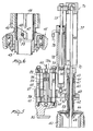
- Figure 2 is a partly sectional elevation view of a second embodiment of an inventive machine, also shown during its normal knitting operation step;
- Figure 3 is a partly sectional elevation view of the top portion of the machine of Figure 1, shown on an enlarged scale in its position of knitted fabric discharge;
- Figure 4 is a sectional view through the bottom portion of the machine of Figure 1, shown on an enlarged scale during the knitted fabric discharge step;
- Figure 5 is a sectional view of the top portion of the machine of Figure 2, shown on an enlarged scale during the knitted fabric discharging step at the end of the knitting operation; and
- Figure 6 is a sectional view through the middle portion of the machine of Figure 2, shown on an enlarged scale during the knitted fabric discharge step.
- kaking initial reference to Figures 1,3 and 4, a circular knitting machine according to the invention, in particular for knitting hosiery,comprises, in accordance with a first embodiment thereof, a fixed or
stationary structure 1 which carries aneedle cylinder 3 rotatable in bearings 2. The needle cyl-inder 3 extends downwardly into a tubular element 4 which supports adischarge box 5, also arranged to rotate with thecylinder 3. At the bottom of thebox 5 there is provided anon-rotating discharge tube 6, which is connected to thebox 5 throughbearings 7 and communicates to a suction vacuum source, not shown, for sucking out the knitwork in a manner known per se. - To the
stationary structure 1 there is attached asupport 8 which supports twoparallel uprights 9 extending in a vertical direction, and accordingly parallel to the axis of thecylinder 3. Theuprights 9 carry, at their top ends, afixed arm 10, which extends substantially radially with respect to the machine. Along theuprights 9, a supportingarm 11 is slidably mounted which also extends substantially radial to the machine and is driven by means of a pneumatically or hydraulically operatedcylinder 12, fastened to thearm 10, the piston of which cylinder has arod 13 which extends parallel to theuprights 9 and is connected to the supportingarm 11. Thecylinder 12 is connected, throughlines lines arm 11, as will be explained hereinafter. - The
arm 11 rotatably carries adial 16, which is arranged coaxially with thecylinder 3, through a hollow substantially cylindrical supportingbody 17, which supports thedial 16 coaxially and rigidly from below, and is in turn held at the top by aspring 18 stretched between aplate 19, adjustably secured on thesupport body 17, and abearing 20 carried on thearm 11. Thespring 18 urges thedial 16, through the support body orholder 17, againstbearings 21 which separate rotation-wise thedial 16 from afixed cover 22 which carries, in a manner known per se, the cams controlling the needles or hooks in thedial 16, the dial, therefore, being in turn urged against thearm 11 with the interposition of acylindrical spacer element 23. Thus, by shifting thearm 11 vertically as described above, thedial 16 is also moved vertically, as may be required for checking purposes or for cleaning operations within the loop formation area. In normal operating conditions, the pressure of the fluid in thecylinder 12 will keep thearm 11, and consequently thedial 16, at a stable lower position. - The
dial 16 is driven relatively through thecylinder 3 by a coupling means located inside thecylinder 3 and comprising arod 24 coaxial with the cylinder and dial, which rod 24. is rotatively connected to the dial through a prismatic coupling means defined by agrooved body 25 being rigid with therod 24 and in engagement with a mating configuration of the interior of a lower conical portion 17a of thesupport body 17. This type of coupling allows therod 24 to be shifted axially while retaining its rotary engagement with thedial 16. The prismatic coupling advantageously extends over a length which is at least equal to the axial displacement length of therod 24. - The
rod 24 has atop portion 26 of increased diameter, which is connected to therod 27 of a piston movable within a pneumatic orhydraulic cylinder 28 attached to thearm 10 and lying coaxially with therod 24. The connection between theportion 26 ofrod 24 androd 27 is preferably a fixed one, while the connection between therod 27 and related piston is of the rotatable type, such as to allow the piston to slide within thefixed cylinder 28 without hindering the rotation of therod 24. Thecylinder 28 is connected, throughlines rod 24 is enabled to move up and down in a programmed way between two extreme positions, one of which being a position of coupled relationship with thecylinder 3 for rotation therewith, the other being a position of disengagement from thecylinder 3. - To this end, the lower or bottom end of the
rod 24 is formed with abevel 31 on one side, and is insertable through ahole 32 formed in anentrainment element 33 so attached to thebox 5 as to be rotatively and axially rigid with respect to thecylinder 3. Apin 34, extending perpendicularly to therod 24 and protruding with its lateral surface into thehole 32, is also arranged in theentrainment element 33. At the extreme bottom position of therod 24, thebevel 31 on therod 24 engages thepin 34, thus making saidrod 24 rigid with theentrainment element 33 and hence with thecylinder 3 for rotation therewith, said engagement being ensured and stabilized by the pressure acting on the piston in thecylinder 28. Thus, thedial 16 is caused to rotate through thecylinder 3, in a constant an- glllar relationship therewith, during normal knitting, as shown in Figure 1. - At the other extreme position of the
rod 24, that is the top position (Figure 3), therod 24 is disengaged from the entrainment element 33 (Figure 4), thus uncovering a discharge pathway for the knittedfabric 35 which has been formed around therod 24 itself. In order to allow the knittedfabric 35 to be discharged, theentrainment element 33 is formed at the top with aninclined surface 36 which directs the fabric downwardly. - Advantageously, within the
cylinder 3 and related extension 4, a guidingtube 37 may be provided for thefabric 35, which tube would extend as far as thedischarge box 5. - The length of the
rod 24 between the portion which rotatively engages with thedial 16 andentrainment element 33 is preferably slightly longer than the knittedfabric 35 expected to be knitted. However, it may be made shorter, since it is possible for the knitwork to gather at theentrainment element 33 before it is discharged. - Advantageously, a
microswitch 36 may be provided to automatically operate the machine as therod 24 is brought into its bottom position of engagement with theentrainment element 33, or to automatically stop the machine in the event that therod 24 is raised out of its bottom position of engagement with theentrainment element 33. - Figures 2,5 and 6 illustrate another embodiment of the machine according to this invention, wherein the
entrainment element 39 is arranged within theneedle cylinder 40, at the lower portion thereof. Thecylinder 40 is carried rotatably on astationary portion 41 of the machine throughbearings 42 and extends into atubular element 43. To thetubular element 42 there is connected throughbearings 44, adischarge tube 45 for the knittedfabric 46. Theentrainment element 39, which is formed at the top with an inclined surface for discharging the knitted fabric, has ahole 47 andpin 48 for engagement with a bevelled bottom end of arod 49, being the equivalent of therod 24 in the first embodiment of the invention. The engagement is effected in the same manner as described with reference to the first embodiment, except that thehole 47 is a blind hole rather than a through hole. - In the embodiment shown in Figures 2,5 and 6, a
stationary portion 50 of the machine supports twouprights 51 which are parallel to each other and to the machine axis, along which uprights anarm 52 is slidable which extends substantially radially with respect to thecylinder 40 and rotatably carries adial 53, as explained hereinafter. Thearm 52 has, located between the twouprights 51, acylindrical protuberance 54, wherein achamber 55 is defined which accommodates apiston 56 having itsrod 57 attached to thestationary portion 50. Thechamber 55 is closed at the bottom by a closure or shutterbody 58, attached to thearm 52, and communicates at the top, through athroughgoing hole 59 in theprotuberance 54 and aconduit 60,with a pressure source, not shown. By supplying a pressurized fluid into thechamber 55 above thepiston 56, thearm 52 is caused to move upwardly, thereby thedial 53 is lifted vertically to provide access to the loop formation area. The downward movement is produced in this case by the structure own weight, to bring thearm 52, in the normal operating condition of the machine, close against twonuts 61, whereby theuprights 51 are respectively fastened to thestationary portion 50. Thedial 53 is secured to a hollow support body 62, of substantially cylindrical configuration, which is carried, through aspring 63 andbearings 64, on asleeve 65 attached to thearm 52 coaxially with thecylinder 40. Thesleeve 65 is a part of a fixedcover 66 of the dial which accommodates the control cams for the dial needles or hooks. The support body 62 is centered within thesleeve 65 and with respect to thecover 66 bybearings dial 53 is also coaxial with thecylinder 40. - At the support body 62, the
rod 49 has on its lateral surface alongitudinally extending groove 70, whereinto atooth 71, attached to the support body 62, engages for rotary engagement of therod 49 with the diel 53, while allowing a relative axial sliding movement between the rod and dial. Of course, both thegroove 70 andtooth 71 should be precision machined to prevent any relative angular movements between therod 49 anddial 53. - For the axial displacement of the
rod 49 between its two extreme positions, respectively corresponding to the position of engagement with the entrainment element 39 (Figure 2) and position of disengagement therefrom (Figure 6), there is provided a pneumatic or hydraulic unit which comprises acylinder 72 having alug 73 attached to the top of theuprights 51 and formed with an opening 73a for the passage of theprotuberance 54. In thecylinder 72, apiston 74 is slidable whoserod 75 is attached, on the outside of thecylinder 72, to astructure 76 carrying therod 49 rotatably. Advantageously, between the bearingstructure 76 and support body 62, aprotective tube 77 is provided. Thecylinder 72 is connected, on either sides of thepiston 74, and through conduits orlines piston 74 allows the engagement of therod 49 with theentrainment element 39 to be maintained under pressure action. The delivery of pressurized fluid to the region underlying thepiston 74 produces the lifting thereof into the position shown in Figure 5, and hence the disengagement of therod 49 from the entrainment element 39 (Figure 6) , In comparison to the embodiment shown in figures 1, 3 and 4, the latter embodiment has the advantage of reducing the overall height dimension of the machine. - It will be appreciated from the foregoing description that both the above embodiments provide a rotary connection between the cylinder and dial in a most simple manner and at the expense of a very moderate constructional complexity. In fact, there are no longer provided gear drives for rotating the dial nor a sleeve element movable axially within the cylinder (or tubular element rotating therewith) and controllable from the outside. The axial displacement of the rod which connects the cylinder to the dial enables the arrangement of a pneumatic or hydraulic unit coaxial or parallel with the rod, thereby simplifying the connection between the stationary parts and rotatable or axially displaceable parts. The pneumatic or hydraulic drive, moreover, readily lends itself to automation, in that it only requires programmed actuation of solenoid valves.
- The invention as described is susceptible to many modifications and variations without departing from the scope of the instant inventive concept. Thus, as an example, engagement means could be provided between the
rod respective entrainment element
Claims (14)
Applications Claiming Priority (2)
| Application Number | Priority Date | Filing Date | Title |
|---|---|---|---|
| IT21597/81A IT1138774B (en) | 1981-05-08 | 1981-05-08 | CIRCULAR MACHINE FOR KNITWEAR OF THE CYLINDER AND PLATEL TYPE, IN PARTICULAR FOR THE MANUFACTURE OF SOCKS |
| IT2159781 | 1981-05-08 |
Publications (2)
| Publication Number | Publication Date |
|---|---|
| EP0065152A1 true EP0065152A1 (en) | 1982-11-24 |
| EP0065152B1 EP0065152B1 (en) | 1985-03-20 |
Family
ID=11184133
Family Applications (1)
| Application Number | Title | Priority Date | Filing Date |
|---|---|---|---|
| EP82103667A Expired EP0065152B1 (en) | 1981-05-08 | 1982-04-29 | Circular knitting machine of the cylinder and dial type, in particular for knitting hosiery |
Country Status (5)
| Country | Link |
|---|---|
| US (1) | US4454729A (en) |
| EP (1) | EP0065152B1 (en) |
| JP (1) | JPS57199846A (en) |
| DE (1) | DE3262612D1 (en) |
| IT (1) | IT1138774B (en) |
Cited By (3)
| Publication number | Priority date | Publication date | Assignee | Title |
|---|---|---|---|---|
| EP0485924A1 (en) * | 1990-11-15 | 1992-05-20 | S.F.I.M. S.r.l. | Single-cylinder circular machine with improved platen actuation, in particular for manufacturing socks, stockings and the like |
| EP1098019A1 (en) * | 1999-11-03 | 2001-05-09 | Sangiacomo S.p.A. | Dial for circular knitting and hosiery machines with height adjustment and which can be stopped, even when the machine is operating |
| KR200469729Y1 (en) * | 2011-08-23 | 2013-11-05 | 주식회사 동성정밀 | A change speed apparatus of circular machine for knitted of socks |
Families Citing this family (10)
| Publication number | Priority date | Publication date | Assignee | Title |
|---|---|---|---|---|
| FR2668505B1 (en) * | 1990-10-24 | 1995-05-05 | Nagata Seiki Kk | DEVICE FOR TRANSFERRING A KNIT FROM A CIRCULAR KNITTING MATERIAL. |
| US5575162A (en) * | 1995-10-03 | 1996-11-19 | Guilford Mills, Inc. | Apparatus for controlling twist in a knitted fabric |
| IT1284002B1 (en) * | 1996-04-22 | 1998-05-08 | Lonati Spa | CIRCULAR SINGLE-CYLINDER MACHINE FOR Hosiery OR KNITWEAR, PARTICULARLY FOR THE PRODUCTION OF CLOSED PRODUCTS IN |
| IT1289504B1 (en) * | 1996-12-20 | 1998-10-15 | Lonati Spa | PROCEDURE FOR THE PRODUCTION OF TUBULAR PRODUCTS, OF THE TYPE OF SOCKS OR SIMILAR, WITH A SINGLE CYLINDER CIRCULAR MACHINE |
| US6735988B1 (en) | 2002-03-27 | 2004-05-18 | Honeycutt Larry W | Cotton footie and stocking |
| US6519980B1 (en) | 2002-04-03 | 2003-02-18 | Sara Lee Corporation | Hosiery dewrinkling system and method for circular knitting machines |
| US6810694B2 (en) | 2003-03-05 | 2004-11-02 | Sara Lee Corporation | Method of knitting an elastomeric yarn into a circularly knitted fabric |
| ITBS20070104A1 (en) * | 2007-07-24 | 2009-01-25 | Santoni & C Spa | MONOCYLINDER CIRCULAR MACHINE FOR MEN'S SOCKS WITH BALL NEEDLES |
| US7793523B1 (en) | 2009-10-01 | 2010-09-14 | Innovative Designs, LLC | Circular knitting machine with bearing-stabilized cylinder |
| USD961627S1 (en) * | 2019-06-17 | 2022-08-23 | Santoni S.P.A. | Textile machine |
Citations (3)
| Publication number | Priority date | Publication date | Assignee | Title |
|---|---|---|---|---|
| US1459446A (en) * | 1919-08-27 | 1923-06-19 | Hemphill Co | Inturned welt-knitting machine |
| US1461693A (en) * | 1921-08-10 | 1923-07-10 | Mellor Bromley & Co Ltd | Circular rib-knitting machine |
| GB325731A (en) * | 1929-03-27 | 1930-02-27 | George Blackburn & Sons Ltd | Improvements in circular rib knitting machine |
Family Cites Families (6)
| Publication number | Priority date | Publication date | Assignee | Title |
|---|---|---|---|---|
| US1361291A (en) * | 1920-12-07 | stibbe | ||
| BE675852A (en) * | 1966-02-01 | 1966-06-16 | Armes De Guerre Fab Nat | Device for knitting ribbing on mono-cylindrical knitting machines with several falls |
| US3516268A (en) * | 1968-09-12 | 1970-06-23 | Us Industries Inc | Device for minimizing twisting of circular knit fabric |
| CS177346B1 (en) * | 1975-04-03 | 1977-07-29 | ||
| IT1099924B (en) * | 1978-10-13 | 1985-09-28 | Lonati Cost Mecc | PERFECTED MACHINE FOR THE PRODUCTION OF TUBULAR FABRIC, IN PARTICULAR OF SOCKS |
| US4339932A (en) * | 1979-10-09 | 1982-07-20 | Francesco Lonati | Machine for knitting a tubular fabric |
-
1981
- 1981-05-08 IT IT21597/81A patent/IT1138774B/en active
-
1982
- 1982-04-29 DE DE8282103667T patent/DE3262612D1/en not_active Expired
- 1982-04-29 EP EP82103667A patent/EP0065152B1/en not_active Expired
- 1982-05-03 US US06/373,950 patent/US4454729A/en not_active Expired - Fee Related
- 1982-05-07 JP JP57075556A patent/JPS57199846A/en active Pending
Patent Citations (3)
| Publication number | Priority date | Publication date | Assignee | Title |
|---|---|---|---|---|
| US1459446A (en) * | 1919-08-27 | 1923-06-19 | Hemphill Co | Inturned welt-knitting machine |
| US1461693A (en) * | 1921-08-10 | 1923-07-10 | Mellor Bromley & Co Ltd | Circular rib-knitting machine |
| GB325731A (en) * | 1929-03-27 | 1930-02-27 | George Blackburn & Sons Ltd | Improvements in circular rib knitting machine |
Cited By (3)
| Publication number | Priority date | Publication date | Assignee | Title |
|---|---|---|---|---|
| EP0485924A1 (en) * | 1990-11-15 | 1992-05-20 | S.F.I.M. S.r.l. | Single-cylinder circular machine with improved platen actuation, in particular for manufacturing socks, stockings and the like |
| EP1098019A1 (en) * | 1999-11-03 | 2001-05-09 | Sangiacomo S.p.A. | Dial for circular knitting and hosiery machines with height adjustment and which can be stopped, even when the machine is operating |
| KR200469729Y1 (en) * | 2011-08-23 | 2013-11-05 | 주식회사 동성정밀 | A change speed apparatus of circular machine for knitted of socks |
Also Published As
| Publication number | Publication date |
|---|---|
| DE3262612D1 (en) | 1985-04-25 |
| US4454729A (en) | 1984-06-19 |
| IT8121597A0 (en) | 1981-05-08 |
| IT1138774B (en) | 1986-09-17 |
| JPS57199846A (en) | 1982-12-07 |
| EP0065152B1 (en) | 1985-03-20 |
Similar Documents
| Publication | Publication Date | Title |
|---|---|---|
| EP0065152B1 (en) | Circular knitting machine of the cylinder and dial type, in particular for knitting hosiery | |
| JP5389831B2 (en) | Pickup device for taking out a cylindrical knitted product from a circular knitting machine for hosiery etc. and transferring the taken out product to a unit adapted for further work on the product | |
| EP2250305B1 (en) | Method and apparatus for closing a tubular knitted article at one of its axial ends, at the end of its production cycle on a circular knitting machine for hosiery or the like | |
| KR102215195B1 (en) | Circular knitting machine with an engaging and disengaging mechanism of the hook plate of the dial group | |
| JP7018425B2 (en) | A pickup device for picking up a tubular knit product from a circular knitting machine for socks, etc. and transferring this knit product to a unit configured to perform further movements on the knit product. | |
| EP0026425A2 (en) | Control device for a circular knitting machine, in particular a hose knitting machine | |
| US2694304A (en) | Automatic draw-off device for circular knitting machines | |
| CN107805875B (en) | Sock body positioning and ejection device of integrated sock knitting machine with movable sinker cover | |
| US4339932A (en) | Machine for knitting a tubular fabric | |
| US3159015A (en) | Pneumatic tensioning device for circular knitting machines, particularly for circular machines for making stockings | |
| US2729082A (en) | Automatic take-up means for knitting machines | |
| US5157946A (en) | Apparatus for transferring knitted fabric from circular knitting machine | |
| KR102656125B1 (en) | A pick-up device for picking up tubular knitted articles from a circular knitting machine and delivering the articles to a unit adapted to perform further operations on the articles. | |
| JPH0376851A (en) | Circular knitting machine | |
| US2330269A (en) | Knitting machine | |
| US3826111A (en) | Circular knitting machine suction takeup | |
| US3076326A (en) | Circular knitting machines having a plurality of needle selection cams for the formation of tuck stitch patterns, underwelt patterns and the like | |
| US3913357A (en) | Dial operated stocking toe closer | |
| US3253429A (en) | Knitting machine | |
| GB2054667A (en) | Circular knitting machines | |
| US3823582A (en) | An assembly for both rotatably driving the suction draw-off tube and operating the slitter mechanism of a circular knitting machine | |
| US1652500A (en) | Dial-positioning and yarn-feeding mechanism eos dial knitting machines | |
| EP0107849A2 (en) | A cylinder-and-dial circular knitting machine particularly for knitting hosiery | |
| US2058481A (en) | Circular knitting machine | |
| US1150183A (en) | Circular-fashioning knitting-machine. |
Legal Events
| Date | Code | Title | Description |
|---|---|---|---|
| PUAI | Public reference made under article 153(3) epc to a published international application that has entered the european phase |
Free format text: ORIGINAL CODE: 0009012 |
|
| AK | Designated contracting states |
Designated state(s): DE FR GB |
|
| 17P | Request for examination filed |
Effective date: 19830510 |
|
| GRAA | (expected) grant |
Free format text: ORIGINAL CODE: 0009210 |
|
| AK | Designated contracting states |
Designated state(s): DE FR GB |
|
| REF | Corresponds to: |
Ref document number: 3262612 Country of ref document: DE Date of ref document: 19850425 |
|
| ET | Fr: translation filed | ||
| PLBE | No opposition filed within time limit |
Free format text: ORIGINAL CODE: 0009261 |
|
| STAA | Information on the status of an ep patent application or granted ep patent |
Free format text: STATUS: NO OPPOSITION FILED WITHIN TIME LIMIT |
|
| 26N | No opposition filed | ||
| GBPC | Gb: european patent ceased through non-payment of renewal fee | ||
| PG25 | Lapsed in a contracting state [announced via postgrant information from national office to epo] |
Ref country code: FR Free format text: LAPSE BECAUSE OF NON-PAYMENT OF DUE FEES Effective date: 19861231 |
|
| PG25 | Lapsed in a contracting state [announced via postgrant information from national office to epo] |
Ref country code: DE Effective date: 19870101 |
|
| REG | Reference to a national code |
Ref country code: FR Ref legal event code: ST |
|
| PG25 | Lapsed in a contracting state [announced via postgrant information from national office to epo] |
Ref country code: GB Effective date: 19881121 |