US144192A - Improvement in stove-pipe dampers - Google Patents
Improvement in stove-pipe dampers Download PDFInfo
- Publication number
- US144192A US144192A US144192DA US144192A US 144192 A US144192 A US 144192A US 144192D A US144192D A US 144192DA US 144192 A US144192 A US 144192A
- Authority
- US
- United States
- Prior art keywords
- damper
- pipe
- stove
- improvement
- dampers
- Prior art date
- Legal status (The legal status is an assumption and is not a legal conclusion. Google has not performed a legal analysis and makes no representation as to the accuracy of the status listed.)
- Expired - Lifetime
Links
- 239000002184 metal Substances 0.000 description 3
- 229910052751 metal Inorganic materials 0.000 description 3
- 239000000463 material Substances 0.000 description 2
- 229910001018 Cast iron Inorganic materials 0.000 description 1
- 241000451147 Lacon Species 0.000 description 1
- SGPGESCZOCHFCL-UHFFFAOYSA-N Tilisolol hydrochloride Chemical compound [Cl-].C1=CC=C2C(=O)N(C)C=C(OCC(O)C[NH2+]C(C)(C)C)C2=C1 SGPGESCZOCHFCL-UHFFFAOYSA-N 0.000 description 1
- 238000010276 construction Methods 0.000 description 1
- 230000004048 modification Effects 0.000 description 1
- 238000012986 modification Methods 0.000 description 1
- 230000000717 retained effect Effects 0.000 description 1
Images
Classifications
-
- F—MECHANICAL ENGINEERING; LIGHTING; HEATING; WEAPONS; BLASTING
- F23—COMBUSTION APPARATUS; COMBUSTION PROCESSES
- F23L—SUPPLYING AIR OR NON-COMBUSTIBLE LIQUIDS OR GASES TO COMBUSTION APPARATUS IN GENERAL ; VALVES OR DAMPERS SPECIALLY ADAPTED FOR CONTROLLING AIR SUPPLY OR DRAUGHT IN COMBUSTION APPARATUS; INDUCING DRAUGHT IN COMBUSTION APPARATUS; TOPS FOR CHIMNEYS OR VENTILATING SHAFTS; TERMINALS FOR FLUES
- F23L13/00—Construction of valves or dampers for controlling air supply or draught
- F23L13/02—Construction of valves or dampers for controlling air supply or draught pivoted about a single axis but having not other movement
Definitions
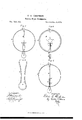
- Fig. 3 a representation of damper-button and the 1neansby which it is attachcd to the damper; and Fig. 4, a view in all respects like Fig. 1, cxcepting that a modification in the construction of the damper is shown.
- A represents a store-pipe.
- B 1 s the dampcr.
- This damper consists of a disk, which may be made either of cast-iron or of sheet metal, and it may either have a central opening, as shown in Fig. 2, for the pnrpose of allowing a moderato draft when the damper is arranged in the position there shown, or it may be somewhat less in diameter than the diameter of the pipe for the same pnrposc.
- 0 is a spindle extending freely through and having a bearing in, an opening in the pipe.
- VVhcn the damper is cast, the spindlc and damper may be cast together in a a are ribs extendingfiom each face of the damper, as shown in Figs. 1 and 2, and when the damper is cast these ribs and the damper may also be cast together in one piece.
- the ribs need not be continuons.
- VVhen the damper is made of sheet metal, the spindie 0 may be attached to it in any snitabIe manner, and the eqnivalents of the ribs a a may be formed by striking or setting np the projections a a by means of a snitable instrument or die, as shown in Fig. 4.
- D is a bntton, by means of which the damper is operated.
- This bntton is preferably made of a material whieh is a poor condnctor of heat; but the material of which it is constrncted is not an essential featnre of my invention.
- a groove is sunken into the periphery of the button, as represcntcd in Fig. 3, and E is a metalhc strip arranged in t]ns groove, and bent in the manner, or approximatmg the form, shown in Fig. 3. It is not essential that the part E slionld be made of spring metal.
- the free ends of the part E are passed throngh a hole in the pipe, and this ho1e is of such a size as to crowd the ends of the part E toward each other, and is arranged opposite the opening in whieh the spindle Orests.
- the part E is then pushed into the pipe nntil its arms enter the grooves or channels formed by the ribs a d, or by their eqnivalents, each arm entering a corresponding groove.
- part E Will thon be retained in the grooves by reason of their contact withthat part of the pipe through Which they pass, bnt may be readiIy withdrawn therefrom.
- the damper may be readi1y opened and closed by tnrnii] g the button for that purposc.
- the arms E E by reason of their contact With the pipe, Will retain the damper in any position in which it may be set.
- the damper B when constrncted snbstantially as speeified, whatever its size may be, Wil1 admit of being operated by means of any button D provided With a part, E, without respect to the length of the arms of the latter part.
- the damper B provided with the spindle C and-with the ribs a a, in eombination With the button D and the arms E, snbstantially as and for the purposes specified.
Landscapes
- Engineering & Computer Science (AREA)
- Chemical & Material Sciences (AREA)
- Combustion & Propulsion (AREA)
- Mechanical Engineering (AREA)
- General Engineering & Computer Science (AREA)
- Air-Flow Control Members (AREA)
Description
E. G. GHAPMAN.
Stove-Pipe Dampers.
Patented Nov. 4,1873.
onc piecc.
EDWIN O. CHAPMAN, OF LAGON, ASSIGNOR OF ONE-HALF HISRIGHT TO JAMES M. HORTON, OF CHICAGO, ILLINOIS.
IMPROVEMENT IN STOVE-PIPE DAMPERS.
Specification forming part 01' Lettcrs Patent No. 144,192, datcd Novembcr 4, 1873; application filed Septembor 5, 1873.
T0 all 207mm it may conccrn:
Be it known that I, EDWIN C. CHAPMAN, of Lacon, in the county of Marshafl and State of Illinois, have invented certain ncw and nsefid Lmprovcments in Dampers for StoVe Pipes, of which improvcments the following is a full, clear, and exact description, whieh Will enable others skiHed in the art to which 1ny invention appcrtains to make and use the same, reference being had to the accompanying drawing, forming apart hereof, and in which Figure 1. is a top view of a stovepipe provided With my in1proved damper, and representing the damper when it is open; Fig. a like view when the damper is closcd; Fig. 3, a representation of damper-button and the 1neansby which it is attachcd to the damper; and Fig. 4, a view in all respects like Fig. 1, cxcepting that a modification in the construction of the damper is shown.
Like letters of reference indicate likc parts. in the drawing, A represents a store-pipe. B 1s the dampcr. This damper consists of a disk, which may be made either of cast-iron or of sheet metal, and it may either have a central opening, as shown in Fig. 2, for the pnrpose of allowing a moderato draft when the damper is arranged in the position there shown, or it may be somewhat less in diameter than the diameter of the pipe for the same pnrposc. 0 is a spindle extending freely through and having a bearing in, an opening in the pipe. VVhcn the damper is cast, the spindlc and damper may be cast together in a a are ribs extendingfiom each face of the damper, as shown in Figs. 1 and 2, and when the damper is cast these ribs and the damper may also be cast together in one piece. The ribs, however, need not be continuons. VVhen the damper is made of sheet metal, the spindie 0 may be attached to it in any snitabIe manner, and the eqnivalents of the ribs a a may be formed by striking or setting np the projections a a by means of a snitable instrument or die, as shown in Fig. 4. D is a bntton, by means of which the damper is operated. This bntton is preferably made of a material whieh is a poor condnctor of heat; but the material of which it is constrncted is not an essential featnre of my invention. A groove is sunken into the periphery of the button, as represcntcd in Fig. 3, and E is a metalhc strip arranged in t]ns groove, and bent in the manner, or approximatmg the form, shown in Fig. 3. It is not essential that the part E slionld be made of spring metal.
In order to attach the button to the damper so that the latter may be operated for the pnrposes for which it is intended, the free ends of the part E are passed throngh a hole in the pipe, and this ho1e is of such a size as to crowd the ends of the part E toward each other, and is arranged opposite the opening in whieh the spindle Orests. The part E is then pushed into the pipe nntil its arms enter the grooves or channels formed by the ribs a d, or by their eqnivalents, each arm entering a corresponding groove. part E Will thon be retained in the grooves by reason of their contact withthat part of the pipe through Which they pass, bnt may be readiIy withdrawn therefrom.
It will be perceived, from the foregoing description, that the damper may be readi1y opened and closed by tnrnii] g the button for that purposc. The arms E E, by reason of their contact With the pipe, Will retain the damper in any position in which it may be set. It will also be perceived that the damper B, when constrncted snbstantially as speeified, whatever its size may be, Wil1 admit of being operated by means of any button D provided With a part, E, without respect to the length of the arms of the latter part. In other words, exact dnplieates of the parts D and E, in clusive of the dimensions of these parts, may be employed for the purposes set forth, in conncction with a damper constructed substantially as describcd, without regard to the size of the latter, and the object of my invention is to accomplish that result by 1neans substantially the same as specified.
Having thns described 1ny invention what I daim as new, and desire to secnre Tny Letters Patent, is-
The damper B, provided with the spindle C and-with the ribs a a, in eombination With the button D and the arms E, snbstantially as and for the purposes specified.
EDXVIN CALVIN CHAPM,N.
Witnesses L. O. MCMURTRIE, Jas. M. HORTON.
Thc arms of the
Publications (1)
| Publication Number | Publication Date |
|---|---|
| US144192A true US144192A (en) | 1873-11-04 |
Family
ID=2213605
Family Applications (1)
| Application Number | Title | Priority Date | Filing Date |
|---|---|---|---|
| US144192D Expired - Lifetime US144192A (en) | Improvement in stove-pipe dampers |
Country Status (1)
| Country | Link |
|---|---|
| US (1) | US144192A (en) |
-
0
- US US144192D patent/US144192A/en not_active Expired - Lifetime
Similar Documents
| Publication | Publication Date | Title |
|---|---|---|
| US144192A (en) | Improvement in stove-pipe dampers | |
| US314121A (en) | Feedeeick j | |
| US184255A (en) | Improvement in stove-pipe dampers | |
| US589610A (en) | Robert mcphaill | |
| US1034507A (en) | Damper. | |
| US13314A (en) | Parlor-stove | |
| US105672A (en) | Joseph hackett | |
| US192395A (en) | Half his eight to a | |
| US56379A (en) | cowan | |
| US257369A (en) | Fire-place | |
| US50133A (en) | Improvement in dampers | |
| US65770A (en) | Charles e | |
| US239895A (en) | Stove-pipe damper | |
| US48952A (en) | Stove-pipe damper | |
| US47448A (en) | Improved chimney | |
| US71711A (en) | James m | |
| US62559A (en) | perry | |
| US71399A (en) | marvin | |
| US152492A (en) | Improvement in stove-pipe dampers | |
| US117762A (en) | Improvement in stove-pipe dampers | |
| US45508A (en) | Improved damper for flues | |
| US62655A (en) | Moses s | |
| US622221A (en) | Flue-stopper | |
| US95340A (en) | Robert ham | |
| US791514A (en) | Chimney-stopper. |