US1361237A - Wrench - Google Patents
Wrench Download PDFInfo
- Publication number
- US1361237A US1361237A US374956A US37495620A US1361237A US 1361237 A US1361237 A US 1361237A US 374956 A US374956 A US 374956A US 37495620 A US37495620 A US 37495620A US 1361237 A US1361237 A US 1361237A
- Authority
- US
- United States
- Prior art keywords
- jaw
- wrench
- keeper
- tooth
- notches
- Prior art date
- Legal status (The legal status is an assumption and is not a legal conclusion. Google has not performed a legal analysis and makes no representation as to the accuracy of the status listed.)
- Expired - Lifetime
Links
Images

Classifications
-
- B—PERFORMING OPERATIONS; TRANSPORTING
- B25—HAND TOOLS; PORTABLE POWER-DRIVEN TOOLS; MANIPULATORS
- B25B—TOOLS OR BENCH DEVICES NOT OTHERWISE PROVIDED FOR, FOR FASTENING, CONNECTING, DISENGAGING, OR HOLDING
- B25B13/00—Spanners; Wrenches
- B25B13/48—Spanners; Wrenches for special purposes
- B25B13/50—Spanners; Wrenches for special purposes for operating on work of special profile, e.g. pipes
- B25B13/5008—Spanners; Wrenches for special purposes for operating on work of special profile, e.g. pipes for operating on pipes or cylindrical objects
- B25B13/5016—Spanners; Wrenches for special purposes for operating on work of special profile, e.g. pipes for operating on pipes or cylindrical objects by externally gripping the pipe
- B25B13/5025—Spanners; Wrenches for special purposes for operating on work of special profile, e.g. pipes for operating on pipes or cylindrical objects by externally gripping the pipe using a pipe wrench type tool
- B25B13/5041—Spanners; Wrenches for special purposes for operating on work of special profile, e.g. pipes for operating on pipes or cylindrical objects by externally gripping the pipe using a pipe wrench type tool with movable or adjustable jaws
- B25B13/5058—Linearly moving or adjustable, e.g. with an additional small tilting or rocking movement
-
- B—PERFORMING OPERATIONS; TRANSPORTING
- B25—HAND TOOLS; PORTABLE POWER-DRIVEN TOOLS; MANIPULATORS
- B25B—TOOLS OR BENCH DEVICES NOT OTHERWISE PROVIDED FOR, FOR FASTENING, CONNECTING, DISENGAGING, OR HOLDING
- B25B13/00—Spanners; Wrenches
- B25B13/10—Spanners; Wrenches with adjustable jaws
- B25B13/12—Spanners; Wrenches with adjustable jaws the jaws being slidable
- B25B13/20—Arrangements for locking the jaws
- B25B13/22—Arrangements for locking the jaws by ratchet action or toothed bars
-
- B—PERFORMING OPERATIONS; TRANSPORTING
- B25—HAND TOOLS; PORTABLE POWER-DRIVEN TOOLS; MANIPULATORS
- B25B—TOOLS OR BENCH DEVICES NOT OTHERWISE PROVIDED FOR, FOR FASTENING, CONNECTING, DISENGAGING, OR HOLDING
- B25B13/00—Spanners; Wrenches
- B25B13/10—Spanners; Wrenches with adjustable jaws
- B25B13/28—Spanners; Wrenches with adjustable jaws the jaws being pivotally movable
Definitions
- This invention relates to an improvement in wrenches, and is particularly directed to a means whereby the wrench may be rapidly and easily adjusted to accommodate different size objects.
- the improved wrench is constructed to permit a manual adjustment of the movable jaw with respect to the fixed jaw, through rranging such movable jaw in any one of a series of notches carried by the fixed jaw, the construction insuring a maintenance of the adjusted position in the use of the wrench as such.
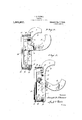
- Figure 1 is a perspective view of my improved wrench.
- Fig. 2 is a view in elevation showing the parts of the wrench in one adjusted position for use.
- Fig. 3 is a similar view showing the movable jaw in a position permitting its adjustment relative to the fixed jaw.
- Fig. 4 is an edge view of the wrench.
- the improved wrench comprises a fixed jaw 1, here shown as with a rounded jaw proper 2 serrated or roughened on the inner surface at 3.
- the outer edge of the handle portion of this jaw 1 is formed in a series of spaced notches 4:, these notches having the upper wall 5 at a materially great angle to the longitudinal plane of the jaw than the lower wall 6.
- the movable jaw 7 having the rounded serrated jaw proper 8 has a straight portion 9 formed with the recess 10 in which the handle portion of the jaw 1 is slidable.
- the outer edge of the recess or opening 10 is formed with a projection or tooth 11 adapted to snugly fit any one of the recesses 4.
- the opposite wall-12 of the opening 10 is inclined with respect to the longitudinal plane of the jaw 7, the inclination being such that when such wall or edge 12 is in contact with the fixed jaw 1 the tooth 11 is beyond the recesses of the jaw 1.
- a keeper is arranged to overlie the tooth end of the jaw 7, such keeper comprising a bar 13 having inwardly extending arms 14, which engage the respective side surfacesof the jaw 1, and are movably connected thereto Specification of Letters Patent.
- the wrench is adapted to be used as any ordinary wrench, while at the same time the. adaptability of the adjustment permits a wide range of normal spacing between the jaws proper, and hence a highly desirable utility of wrench structure.
- a wrench comprising 'a fixed jaw, formed with notches, a sliding jaw having a tooth to engage any one of said notches, a keeper adapted to bear squarely against the end of the movable jaw when the tooth is in its notch, and spring means for holding the keeper in operative position.
- a wrench comprising a fixed jaw formed with notches, a sliding jaw having a tooth to engage any one of said notches, a keeper movably mounted on the fixed jaw and adapted to engage the end of the movable jaw when in operative position, and spring means for normally holding the keeper in operative position.
- a wrench comprising a fixed jaw formed with notches, a sliding jaw having a tooth adapted to engage any one of said notches, a keeper formed of a bar having lateral extensions from the ends thereof slidably engaging the fixed jaw, the bar of the keeper being adapted to engage the end of the sliding jaw when in operative position, and springs for normally holding the keeper in operative position.
- a wrench comprising a fixed jaw formed with notches, a sliding jaw having a tooth adapted to engage anyl one of said notches, a keeper for engaging the end of the sliding jaw when in operative position, said keeper beingformed of a U-shaped bar having the ends slidably engaged with the fixed jaw, and springs having the ends secured to the keeper and fixed jaw for normally holding the keeper in operative position.
Landscapes
- Engineering & Computer Science (AREA)
- Mechanical Engineering (AREA)
- Details Of Spanners, Wrenches, And Screw Drivers And Accessories (AREA)
Description
J. B. FLEENOR.
WRENCH.
APPLICATION FILED APR. 19, 1920.
W 0 m Mm m e a; e m n H v B A m H 1M/ M M J v UNITED STATES PALIENT OFFICE.
JOSEPH B. FLEEN'OR, 0F SEATTLE, WASHINGTON.
WRENCH.
Application med April 19, 1920. Serial No. 374,956.
To all whom it may concern:
Be it known that I, JosEPH B. FLEnNoR, a citizen of the United States, and residing at Seattle, in the county of King and State of Washington, have invented certain new and useful Improvements in Wrenches, of which the following is a specification.
This invention relates to an improvement in wrenches, and is particularly directed to a means whereby the wrench may be rapidly and easily adjusted to accommodate different size objects.
The improved wrench is constructed to permit a manual adjustment of the movable jaw with respect to the fixed jaw, through rranging such movable jaw in any one of a series of notches carried by the fixed jaw, the construction insuring a maintenance of the adjusted position in the use of the wrench as such.
In the drawings Figure 1 is a perspective view of my improved wrench.
Fig. 2 is a view in elevation showing the parts of the wrench in one adjusted position for use.
Fig. 3 is a similar view showing the movable jaw in a position permitting its adjustment relative to the fixed jaw.
Fig. 4 is an edge view of the wrench.
The improved wrench comprises a fixed jaw 1, here shown as with a rounded jaw proper 2 serrated or roughened on the inner surface at 3. The outer edge of the handle portion of this jaw 1 is formed in a series of spaced notches 4:, these notches having the upper wall 5 at a materially great angle to the longitudinal plane of the jaw than the lower wall 6. The movable jaw 7 having the rounded serrated jaw proper 8 has a straight portion 9 formed with the recess 10 in which the handle portion of the jaw 1 is slidable. The outer edge of the recess or opening 10 is formed with a projection or tooth 11 adapted to snugly fit any one of the recesses 4. The opposite wall-12 of the opening 10 is inclined with respect to the longitudinal plane of the jaw 7, the inclination being such that when such wall or edge 12 is in contact with the fixed jaw 1 the tooth 11 is beyond the recesses of the jaw 1.
A keeper is arranged to overlie the tooth end of the jaw 7, such keeper comprising a bar 13 having inwardly extending arms 14, which engage the respective side surfacesof the jaw 1, and are movably connected thereto Specification of Letters Patent.
by pin and slot connection 15. Springs 16 secured to the jaw 1 and to pins 17 at the respective ends of the keeper, serve to hold such keeper at the inner limit of movement.
As will be noted from Fig. 1 of the drawings that end of the jaw 7 remote from the jaw proper thereof will when the tooth 11 engages a particular notch 4 be in parallelism with the keeper bar 13, so that in this position said keeper bar under the tension of the springs 16 serve to hold the movable jaw in the particular notch for the wrench operation. When it is desired to adjust the movable jaw to a new position, it is turned until the wall 12 of the opening 10 is forced into contact with the adjacent edge of the handle portion of the jaw 1. This action is of course against the tension of the springs 16, and forces the keeper outwardly, at the same time forcing the tooth 11 from the particular notch. Theedge 12 now operates as a sliding base on which the movable jaw may be moved to the new position, and released. The keeper then acts to force the movable jaw to a position to cause proper coaction between the tooth 11 and the selected notch.
It is of course apparent that with the movable jaw held by the notch and tooth engagement, the wrench is adapted to be used as any ordinary wrench, while at the same time the. adaptability of the adjustment permits a wide range of normal spacing between the jaws proper, and hence a highly desirable utility of wrench structure.
What I claim is:
1. A wrench comprising 'a fixed jaw, formed with notches, a sliding jaw having a tooth to engage any one of said notches, a keeper adapted to bear squarely against the end of the movable jaw when the tooth is in its notch, and spring means for holding the keeper in operative position.
2. A wrench comprising a fixed jaw formed with notches, a sliding jaw having a tooth to engage any one of said notches, a keeper movably mounted on the fixed jaw and adapted to engage the end of the movable jaw when in operative position, and spring means for normally holding the keeper in operative position.
3. A wrench comprising a fixed jaw formed with notches, a sliding jaw having a tooth adapted to engage any one of said notches, a keeper formed of a bar having lateral extensions from the ends thereof slidably engaging the fixed jaw, the bar of the keeper being adapted to engage the end of the sliding jaw when in operative position, and springs for normally holding the keeper in operative position.
4. A wrench comprising a fixed jaw formed with notches, a sliding jaw having a tooth adapted to engage anyl one of said notches, a keeper for engaging the end of the sliding jaw when in operative position, said keeper beingformed of a U-shaped bar having the ends slidably engaged with the fixed jaw, and springs having the ends secured to the keeper and fixed jaw for normally holding the keeper in operative position.
Intestimony whereof I aflix mv signature.
. JOSEPH B. FLEENOR.
Priority Applications (1)
| Application Number | Priority Date | Filing Date | Title |
|---|---|---|---|
| US374956A US1361237A (en) | 1920-04-19 | 1920-04-19 | Wrench |
Applications Claiming Priority (1)
| Application Number | Priority Date | Filing Date | Title |
|---|---|---|---|
| US374956A US1361237A (en) | 1920-04-19 | 1920-04-19 | Wrench |
Publications (1)
| Publication Number | Publication Date |
|---|---|
| US1361237A true US1361237A (en) | 1920-12-07 |
Family
ID=23478894
Family Applications (1)
| Application Number | Title | Priority Date | Filing Date |
|---|---|---|---|
| US374956A Expired - Lifetime US1361237A (en) | 1920-04-19 | 1920-04-19 | Wrench |
Country Status (1)
| Country | Link |
|---|---|
| US (1) | US1361237A (en) |
-
1920
- 1920-04-19 US US374956A patent/US1361237A/en not_active Expired - Lifetime
Similar Documents
| Publication | Publication Date | Title |
|---|---|---|
| US1511340A (en) | Combination tool | |
| US1651216A (en) | Pliers | |
| US1727623A (en) | Wrench | |
| US1627035A (en) | Wrench | |
| US1361237A (en) | Wrench | |
| US1564222A (en) | Wrench | |
| US1635930A (en) | Wrench | |
| US1126678A (en) | Wrench. | |
| US1467709A (en) | Wrench | |
| US1500314A (en) | Wrench | |
| US1368966A (en) | Pipe-wrench | |
| US1423499A (en) | Wrench | |
| US1459583A (en) | Adjustable wrench | |
| US1441372A (en) | Adjustable wrench | |
| US1454333A (en) | Wrench | |
| US1570586A (en) | Wrench | |
| US1326172A (en) | Sire-hydrant wrei | |
| US1264895A (en) | Wrench. | |
| US1003556A (en) | Wrench. | |
| US1663920A (en) | Wrench | |
| US1808001A (en) | Pipe wrench | |
| US1303709A (en) | Wrench | |
| US1526749A (en) | Wrench | |
| US1721118A (en) | Monkey wrench | |
| US1545325A (en) | Wire stretcher |