US1331663A - Oil-cup - Google Patents
Oil-cup Download PDFInfo
- Publication number
- US1331663A US1331663A US324465A US32446519A US1331663A US 1331663 A US1331663 A US 1331663A US 324465 A US324465 A US 324465A US 32446519 A US32446519 A US 32446519A US 1331663 A US1331663 A US 1331663A
- Authority
- US
- United States
- Prior art keywords
- cup
- lid
- pintle
- oil
- bearings
- Prior art date
- Legal status (The legal status is an assumption and is not a legal conclusion. Google has not performed a legal analysis and makes no representation as to the accuracy of the status listed.)
- Expired - Lifetime
Links
- 210000003811 finger Anatomy 0.000 description 4
- 238000005461 lubrication Methods 0.000 description 4
- 238000010276 construction Methods 0.000 description 2
- 238000007790 scraping Methods 0.000 description 2
- 238000009987 spinning Methods 0.000 description 2
- 210000003813 thumb Anatomy 0.000 description 2
- 230000000694 effects Effects 0.000 description 1
- 239000000314 lubricant Substances 0.000 description 1
- 238000003825 pressing Methods 0.000 description 1
- 238000005096 rolling process Methods 0.000 description 1
- 238000003892 spreading Methods 0.000 description 1
Images
Classifications
-
- F—MECHANICAL ENGINEERING; LIGHTING; HEATING; WEAPONS; BLASTING
- F16—ENGINEERING ELEMENTS AND UNITS; GENERAL MEASURES FOR PRODUCING AND MAINTAINING EFFECTIVE FUNCTIONING OF MACHINES OR INSTALLATIONS; THERMAL INSULATION IN GENERAL
- F16N—LUBRICATING
- F16N21/00—Conduits; Junctions; Fittings for lubrication apertures
- F16N21/06—Covering members for nipples, conduits or apertures
Definitions
- My invention relates to lidded oil cups designed for the reception of lubricants and the like; and my improvements are particularly directed to means for securing a durable and simple construction which will increase the simplicity and efliciency with which the lid of the cup may be opened and closed as desired.
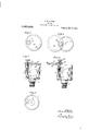
- FIG. 2 is a vertical sectional view of the same;
- Fig. 3 is a top view with the lid opened;
- Fig. i is a vertical sectional view of the same; and
- Fig. 5 is a top view of the cup with the lid removed. Similar parts are designated by corresponding reference numerals in all the figures.
- the body 1 of the oil cup is provided with an oil duct 2 passing down through its bottom and through a suitable, screw threaded neck 3, by which it may be secured in an operative position.
- pivot bearings i and 5 the former consisting of a socket and the latter of a sleeve, these bearings being preferably made integral with the body of the cup. And in these bearings ro tates and slides a pintle 6, having a coiled spring 7 surrounding it and interposed between the bearing 5 and a suitable stop on the pintle, as a washer 8 supported by a pin 9.
- the upper end of the pintle 6 is threaded and is screwed through a threaded opening 10 in the lid 11. And upon the upper ead of the pintle 6 is screwed a knob 12 which acts as a nut lock and clamps the pintle and lid firmly together.
- the lid 11 is preferably provided with a flange 13 which is adapted to fit inside of the cup, when the lid is closed, and to ride smoothly on the upper edge of the cup when the lid is opened, which arrangement results in the edge of the cup scraping oit from the lid and retaining any surplus oil which may be adhering to the lower edge of the flange when the lid is swung open.
- This effect is increased by the tension of the spring 7 1 is a top view of which holds the lid when opened snugly against the edge of the cup, as well as keeps it closed when swung into place.
- the knob In use the knob is grasped between the thumb and fingers and raised so as to bring the lid up to the edge of the cup. At the same time the knob is given a slight sidewise twist or spin, so that as soon as its flange 13 is even with the edge of the cup it will swing outward, scraping along the cups edge as it does so. This movement of the lid is continued by rolling the knob between the thumb and fingers until the lid is as far open as desired. And by spinning the knob in the reverse direction the lid will be swung back so as to cover the cup and will be pulled down into place by the spring 7.
- This arrangement provides a cup lid which is raised and manipulated by a finger hold placed directly in line with its carrying pivot, thus avoiding any tendency of the pintle to bind in the bearings, which furthermore are constantly lubricated by the oil in the cup.
- the knob 12 being so disposed in line with the pintle and being of a suitable form to be grasped and spun between the fingers the whole operation of opening and closing the lid may be performed without altering the grip of the tingers upon the knob or swinging the operators hand or arm in manipulating the lid.
- My arrangement therefore gives compactness and durability of construction, simplicity and efficiency of operation and prevents the spreading of the oil from within the cup upon its outer side when the lid is swung open.
- a lid provided With a vice, of a cup having an outlet duct, a horihorizontal under edge and With a flange havzontal upper edge and interior pintle bear ing a horizontal lower edge adapted to regings, a lid provided With a flange having a ister inside of the cup, a pintle sliding and 10 horizontal lower edge and being adapted to rotating in the bearings and threaded 25 register inside of the cup, a pintle sliding through and carrying the lid, a coiled, de and rotating in the bearings and threaded pressing spring carried by the pintle, and a through and carrying the lid and being prorounded lifting and spinning knob threaded vided with a lifting and rotating element onto the end of the pintle above thelid. 15 consisting of a rounded knob above the lid CHARLES H. NEWTON.
Landscapes
- Engineering & Computer Science (AREA)
- General Engineering & Computer Science (AREA)
- Mechanical Engineering (AREA)
- Closures For Containers (AREA)
Description
C. H. NEWTON.
OIL CUP. APPLICATION FILED SEPT. 18, 19:9.
Patented Feb. 24, 1920.
I. 1, llll 0 2 Z J 4 0 70 0 Wll Es: 4 J %A// 7. WM 9 1 na J I VENTOR 4 m BY ATTORNEY CHARLES H. NEWTON, 0F PLAINVILLE, CONNECTICUT.
OIL-CUP.
Specification of Letters Patent.
Patented Feb. 24, 1920.
Application filed September 18, 1919. Serial No. 324,465.
To all whom it may concern:
Be it known that I, CHARLES H. NEWTON. a citizen of the United States, and resident of Plainville, in the county of Hartford and State of Connecticut, have invented certain new and useful Improvements in Oil- Cups, of which the following is a specification.
My invention relates to lidded oil cups designed for the reception of lubricants and the like; and my improvements are particularly directed to means for securing a durable and simple construction which will increase the simplicity and efliciency with which the lid of the cup may be opened and closed as desired.
In the drawings Figure my improved oil cup with the lid closed; Fig. 2 is a vertical sectional view of the same; Fig. 3 is a top view with the lid opened; Fig. i is a vertical sectional view of the same; and Fig. 5 is a top view of the cup with the lid removed. Similar parts are designated by corresponding reference numerals in all the figures.
The body 1 of the oil cup is provided with an oil duct 2 passing down through its bottom and through a suitable, screw threaded neck 3, by which it may be secured in an operative position.
It is also provided interiorly with pivot bearings i and 5, the former consisting of a socket and the latter of a sleeve, these bearings being preferably made integral with the body of the cup. And in these bearings ro tates and slides a pintle 6, having a coiled spring 7 surrounding it and interposed between the bearing 5 and a suitable stop on the pintle, as a washer 8 supported by a pin 9.
The upper end of the pintle 6 is threaded and is screwed through a threaded opening 10 in the lid 11. And upon the upper ead of the pintle 6 is screwed a knob 12 which acts as a nut lock and clamps the pintle and lid firmly together.
The lid 11 is preferably provided with a flange 13 which is adapted to fit inside of the cup, when the lid is closed, and to ride smoothly on the upper edge of the cup when the lid is opened, which arrangement results in the edge of the cup scraping oit from the lid and retaining any surplus oil which may be adhering to the lower edge of the flange when the lid is swung open. This effect is increased by the tension of the spring 7 1 is a top view of which holds the lid when opened snugly against the edge of the cup, as well as keeps it closed when swung into place.
In use the knob is grasped between the thumb and fingers and raised so as to bring the lid up to the edge of the cup. At the same time the knob is given a slight sidewise twist or spin, so that as soon as its flange 13 is even with the edge of the cup it will swing outward, scraping along the cups edge as it does so. This movement of the lid is continued by rolling the knob between the thumb and fingers until the lid is as far open as desired. And by spinning the knob in the reverse direction the lid will be swung back so as to cover the cup and will be pulled down into place by the spring 7.
This arrangement provides a cup lid which is raised and manipulated by a finger hold placed directly in line with its carrying pivot, thus avoiding any tendency of the pintle to bind in the bearings, which furthermore are constantly lubricated by the oil in the cup. And the knob 12 being so disposed in line with the pintle and being of a suitable form to be grasped and spun between the fingers the whole operation of opening and closing the lid may be performed without altering the grip of the tingers upon the knob or swinging the operators hand or arm in manipulating the lid.
My arrangement therefore gives compactness and durability of construction, simplicity and efficiency of operation and prevents the spreading of the oil from within the cup upon its outer side when the lid is swung open.
Having thus described my invention, What I claim and desire to secure by Letters Patent of the United States is 1. The combination, in a lubrication device, of a cup having an outlet duct, a horizontal upper edge and interior pintle bearings, a lid provided with a flange having a horizontal lower edge and being adapted to register inside of the cup, a pintle sliding and rotating in the bearings and fixed in its relation to and carrying the lid and being provided with a lifting and rotating element above the lid and disposed in line with the pintle.
2. The combination, in a lubrication device, of a cup having an outlet duct, a horizontal upper edge and interior pintle bearings, a lid provided with a flange having a horizontal lower edge and being adapted to register inside of the cup, a pintle sliding and disposed in line with and threaded onto and rotating in the bearings and carrying the pintle. V the lid and being provided with a lifting 4. The combination, in a lubrication deand rotating element consisting of a roundvice, of a cup having an outlet duct, a fiat 5 ed knob and disposed in line with the pintle. horizontal upper edge and integral, inte- 2o 3. The combination, in a lubrication derior pintle bearings, a lid provided With a vice, of a cup having an outlet duct, a horihorizontal under edge and With a flange havzontal upper edge and interior pintle bear ing a horizontal lower edge adapted to regings, a lid provided With a flange having a ister inside of the cup, a pintle sliding and 10 horizontal lower edge and being adapted to rotating in the bearings and threaded 25 register inside of the cup, a pintle sliding through and carrying the lid, a coiled, de and rotating in the bearings and threaded pressing spring carried by the pintle, and a through and carrying the lid and being prorounded lifting and spinning knob threaded vided with a lifting and rotating element onto the end of the pintle above thelid. 15 consisting of a rounded knob above the lid CHARLES H. NEWTON.
Priority Applications (1)
| Application Number | Priority Date | Filing Date | Title |
|---|---|---|---|
| US324465A US1331663A (en) | 1919-09-18 | 1919-09-18 | Oil-cup |
Applications Claiming Priority (1)
| Application Number | Priority Date | Filing Date | Title |
|---|---|---|---|
| US324465A US1331663A (en) | 1919-09-18 | 1919-09-18 | Oil-cup |
Publications (1)
| Publication Number | Publication Date |
|---|---|
| US1331663A true US1331663A (en) | 1920-02-24 |
Family
ID=23263707
Family Applications (1)
| Application Number | Title | Priority Date | Filing Date |
|---|---|---|---|
| US324465A Expired - Lifetime US1331663A (en) | 1919-09-18 | 1919-09-18 | Oil-cup |
Country Status (1)
| Country | Link |
|---|---|
| US (1) | US1331663A (en) |
-
1919
- 1919-09-18 US US324465A patent/US1331663A/en not_active Expired - Lifetime
Similar Documents
| Publication | Publication Date | Title |
|---|---|---|
| US1331663A (en) | Oil-cup | |
| US409148A (en) | John haller | |
| US2162445A (en) | Jar wrench | |
| US2450545A (en) | Baton | |
| US1560254A (en) | Wrench cup | |
| US2328833A (en) | Cover operating device for electric roasters | |
| US1923767A (en) | Lubricator | |
| US1046795A (en) | Crane-hook locking attachment. | |
| US1567976A (en) | Chalk-line holder | |
| US1012346A (en) | Lid-opening device for garbage-cans. | |
| CN107973032A (en) | Circular open dustbin | |
| US2285045A (en) | Bulb carrying compartment for handles of electric lanterns | |
| US1288141A (en) | Oil-cup. | |
| US2120681A (en) | Crankcase drain | |
| US1258876A (en) | Charging means for grease-cups. | |
| US1092305A (en) | Oil-can. | |
| US1350721A (en) | Oil-cup | |
| US2335442A (en) | Lubricating device | |
| CN217080053U (en) | Stop mechanism | |
| US1527108A (en) | Oil can | |
| US991047A (en) | Device for manipulating jar-closures. | |
| CN107902297A (en) | Garbage collection bucket | |
| US1541172A (en) | Sirup can | |
| US1496248A (en) | Door-closing device | |
| US784282A (en) | Covered receptacle. |