US1281237A - Machine for casting stepped splice-bars. - Google Patents
Machine for casting stepped splice-bars. Download PDFInfo
- Publication number
- US1281237A US1281237A US22660518A US22660518A US1281237A US 1281237 A US1281237 A US 1281237A US 22660518 A US22660518 A US 22660518A US 22660518 A US22660518 A US 22660518A US 1281237 A US1281237 A US 1281237A
- Authority
- US
- United States
- Prior art keywords
- sections
- mold forming
- mold
- machine
- bar
- Prior art date
- Legal status (The legal status is an assumption and is not a legal conclusion. Google has not performed a legal analysis and makes no representation as to the accuracy of the status listed.)
- Expired - Lifetime
Links
Images

Classifications
-
- B—PERFORMING OPERATIONS; TRANSPORTING
- B28—WORKING CEMENT, CLAY, OR STONE
- B28B—SHAPING CLAY OR OTHER CERAMIC COMPOSITIONS; SHAPING SLAG; SHAPING MIXTURES CONTAINING CEMENTITIOUS MATERIAL, e.g. PLASTER
- B28B7/00—Moulds; Cores; Mandrels
- B28B7/0002—Auxiliary parts or elements of the mould
- B28B7/0014—Fastening means for mould parts, e.g. for attaching mould walls on mould tables; Mould clamps
- B28B7/0017—Fastening means for mould parts, e.g. for attaching mould walls on mould tables; Mould clamps for attaching mould walls on mould tables
-
- B—PERFORMING OPERATIONS; TRANSPORTING
- B22—CASTING; POWDER METALLURGY
- B22C—FOUNDRY MOULDING
- B22C9/00—Moulds or cores; Moulding processes
- B22C9/06—Permanent moulds for shaped castings
- B22C9/062—Mechanisms for locking or opening moulds
Definitions
- the object of my invention is to overcome the objection above mentioned; and I aocomplish my object by providing, a mold forming machine having'mold forming members comprising separable sections which may be removed for the substitution of others in forming, molds for difi'erent splice bars, and which are preferably constructed to form.
- a mold fora splice bar in which the end of the mold which is to form the end of the bar which is to fit a rail of one size is formed of sections of the members which are separable from sections of the members which are to form a mold for the other end of the bar which is tofit a railofanother size, so that theseotions which form the moldforone end of the'bar may be removed and other sections substituted. for them where it is desired to change the character of one end of the mold formed by the members to, cast a splice bar for a different combination of rails.
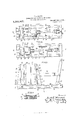
- Figure 1 is a plan of my improved mold forming machine in the open position. 7
- Fig. 2 is a similar view in the closed position.
- Fig. 3 is a side elevation of the machine in the open position.
- Fig; 7 is a perspective view of .one of the sections of one of the mold forming members detached from the machine.
- Fig. 8 is aperspective view of a finished, stepped splice bar.
- F ig.- 9 is a trai'isverse section of a rail joint including two stepped splice bars.
- Fig. 10 isa view of a stepped splice bar as it comes fronr the machine, before the base portion is bent into final position.
- FIG.2 designates the frame of the machine and; it comprises a bed portion'3 and a standard 7 rising from one end-thereof;
- the bed portion 3 includes parallel sidemembers 8 between which is arranged a horizontally movable carriage 9 which is fitted to sli'de on horizontal ,ribs' 10 which project inwardly from the side members 8.
- the carriage 9, is provided with a standard 11 which rises therefrom opposite to the standard 7 on the frame 2.
- the standards ,7 and 11 are adapted to support'two vertically disposed mold forming members 12' and 13, respectively.
- the member 12 comprises two separable' sections l4c and 15 which are arranged adjacent to each other and preferably endto end and one above the other; and the other member 13 comprises two separable sections 16 and 17 which arearranged adjacent to each other and preferably end to end and one above the other.
- the sections 14 and 15 of the member 12 are separately and detachably secured to the standard 7 by means of removable screws 18 and 19, respectively; and the sections 16 and 17 of the member 13 are separately and detachably secured tothe standard 11 by means of removable screws 20 and 21, respectively.
- Thecarri'age' 9 is adapted to be moved toward and fromthe frame standard 7 to move the moldforming member 13 into. and i '29 which extend between the respective faces 26 and 27 of the members 12 and 13 and which will be presently described.
- the mold forming members 12 and 13 are adapted to rest upon ledges or floor portions 30 and 31 which project horizontally from the standards 7 and 11, respectively, as clearly shown in Figs. 5 and 6.
- the floor portion 30 of the standard 7 does not extend to the mold forming face 28 of the member 12, andthe floor portion 31 of the standard 11 extends to and beyond the mold forming face 29 of the member 13 and is adapted to pass beneath and beyond the mold forming face of the member 12 when the carriage 9 is moved to move the member 13 into operative relation to the member 12, as shown in Fig. 6; whereby, when the parts are inthe operative position shown in Fig.
- the floor portion '31 will close the bottom of the mold formed between the faces 28 and 29 and form a means to prevent molten metal from flowing from between the vertical mold forming walls 28 and 29 of the members 12 and 13; and whereby the casting formed by the members 12 and 13 may be dropped down betweenthe standards 7 and 11 and between the side members 8 of the machine frame when the parts are moved to the position shown in Figs, 1 and 5.
- Stepped splice bars are formed so that the respective end portions of the bar from the center thereof outwardly'will properly fit the respective ends of the two rails of different sizes to be joined by the bar, as is well known to persons skilled in this art. Therefore, I construct the mold forming faces 28 and 29 of the sections 14 and 16 of the members 12 and 13 to form one end'of a bar which is adapted to fit against a rail of one size, and 1 construct the mold forming .faces 28 and 29 of the sections 15 and 17 of the members 12 and 13 to form the other end of the same bar adapted to fit against a rail of another size, so that when the member 13 is moved .into operative relation to the member 12 the two complete members will form a mold for a stepped splice, bar which will properly fit against two rail sectionsof predetermined different sizes.
- any desired combination of the sections may be assembled upon the standards 7 and 11 to form a mold for a stepped bar to fit any particular combination of rail sections of different sizes, thereby avoiding the necessity of making a single pattern for the formation of a mold for each bar which is to fit each different combination of rail sections.
- the sections 14 and 15 have their mold forming faces extending parallel to a straight line or parallel to the sides of the rails against which the splice bar is formed to fit, and. the said parallel faces of the section 14 are out of alinement with the said parallel faces of the section 15 to properly some or all of their mold forming faces extending parallel to said line and out of alinement with each other, as the character of the splice bar may dictate, to form the bar with the proper thicknesses of metal in the different partsthereof, all as will be readily understood by persons skilled in this art.
- splice bar 35 illustrated in Figs. 18 and 9 is provided with a base portion 36 adapted to extend beneath and. to support the ends of the rail sections at the joints thereof, and the sections 14, 15, 16' and 17 of the mold forming members 12 and 13 are constructed to form, a splice bar which when finished Will conform to the splice bar shown in Figs. 8 and 9.
- This type of splice bar, when it leaves the mold, is in the form illustrated in Fig.
- the base portion 36 is spaced a greater distance from the rail-engaging portion the bar than in the finished article; and, thereafter, 'while the metal is yet sufiioiently hot topermit it to be bent without injury thereto, the base portion 36 is bent from the condition shown in Fig. 10 to. its final form as shown in Figs. 8 and 9. I f
- sections 14, 15, 16 and 17 may be constructed to form stepped splice bars of many different types.
- a plurality of mold forming members each member comprising two separable sections arranged adjacent to each other, each section having mold forming faces parallel to a straight line, the said faces of one section of each member being out of alinement with the said faces of the other section thereof, means to detachably hold said sections together in a mold forming position, and means to prevent molten metal from flowing from within the mold formed by said sections.
- a plurality of mold forming members each member comprising two separable sections arranged adjacent to each other, each section having mold forming faces parallel to a straight line, the said faces of one section of each member being out of alinement with the said faces of the other section thereof, the sections of one of said members having other mold forming faces parallel to said line and in alinement with each other, means to detachably hold said sections together in a mold forming position, and means to prevent molten metal from flowing from within the mold formed by said sections.
- a mold forming machine for casting stepped splice bars, the combination of a supporting frame, a vertically disposed mold forming member comprising two separable sections arranged end to end and one above the other, means to detachably secure each of said sections to said frame, a carriage movable on said frame toward and from said member, a second vertically disposed mold forming member comprising two separable sections arranged end to end and one above the other, means to detachably secure each section of said second member to said carriage, means operative to move said carriage toward and from the first named member to move the second named member into and from operative relation to the first named member, each of said sections having mold forming faces of different contours which form a mold when said second member is moved into operative relation to the first named member, and a wall closing the bottom of said mold.
Landscapes
- Engineering & Computer Science (AREA)
- Mechanical Engineering (AREA)
- Manufacturing & Machinery (AREA)
- Chemical & Material Sciences (AREA)
- Ceramic Engineering (AREA)
- Molds, Cores, And Manufacturing Methods Thereof (AREA)
Description
B. L. WEAVER. MACHINE FOR CASHNG STEPPED SPLICE BARS.
APPLICATION FILED APRA, 191s. l Lfii Patented Ont. 8,1918.
2 SHEETS-SHEET a a? 2% 7 22 a: w 2% 1; 57'}: 30 h L11. 2 -EH 5 $75.4 &
B. L. WEAVER. MACHINE FOR CASTING STEPPED SPLICE BARS.
SHEET APPLlCATlON FILED APR. 4,1918.
BENT Il. WEAVER, or aremsscee, PENnsYLvAN-I'A.
MACHINE FoR cit-same STEPPED SPLICE-BARS.
Specificatioh of Letters Patent.
Patenteaoet. s, 1918'.
Application filed; April 4, 1918i Serial -N'0 .'22(i;605.
To all whom it may concern: H
Be it known that I, BENT L. WEAVER, a citizen of the United States, residing" at Harrisburg, in the county of Dauphin and State of Pennsylvania,- have invented certain new and useful Improvementsin Macomplete pattern. This has been objection able because it has necessitated the making of a large number of patterns, owing to the large number of combinations of rails of different sizes, resulting in great expense, loss of time and other inconveniences;
The object of my invention is to overcome the objection above mentioned; and I aocomplish my object by providing, a mold forming machine having'mold forming members comprising separable sections which may be removed for the substitution of others in forming, molds for difi'erent splice bars, and which are preferably constructed to form. a mold fora splice bar in which the end of the mold which is to form the end of the bar which is to fit a rail of one size is formed of sections of the members which are separable from sections of the members which are to form a mold for the other end of the bar which is tofit a railofanother size, so that theseotions which form the moldforone end of the'bar may be removed and other sections substituted. for them where it is desired to change the character of one end of the mold formed by the members to, cast a splice bar for a different combination of rails. V
With this object in View my invention consists inthe novel construction and combinations of parts hereinafter described and claimed. V
In the accompanying drawings,illustratingmy invention, l
Figure 1 is a plan of my improved mold forming machine in the open position. 7
Fig. 2 is a similar view in the closed position.
Fig. 3 is a side elevation of the machine in the open position.
the machine onlines 55 and 66 of Figs.
1 and 2, respectively;
Fig; 7 is a perspective view of .one of the sections of one of the mold forming members detached from the machine.
Fig. 8 is aperspective view of a finished, stepped splice bar.
F ig.- 9 is a trai'isverse section of a rail joint including two stepped splice bars.
Fig. 10 isa view of a stepped splice bar as it comes fronr the machine, before the base portion is bent into final position.
Referringto the drawings,;2 designates the frame of the machine and; it comprises a bed portion'3 and a standard 7 rising from one end-thereof; I
The bed portion 3 includes parallel sidemembers 8 between which is arranged a horizontally movable carriage 9 which is fitted to sli'de on horizontal ,ribs' 10 which project inwardly from the side members 8.
The carriage 9, is provided with a standard 11 which rises therefrom opposite to the standard 7 on the frame 2.
The standards ,7 and 11 are adapted to support'two vertically disposed mold forming members 12' and 13, respectively. The member 12 comprises two separable' sections l4c and 15 which are arranged adjacent to each other and preferably endto end and one above the other; and the other member 13 comprises two separable sections 16 and 17 which arearranged adjacent to each other and preferably end to end and one above the other. The sections 14 and 15 of the member 12 are separately and detachably secured to the standard 7 by means of removable screws 18 and 19, respectively; and the sections 16 and 17 of the member 13 are separately and detachably secured tothe standard 11 by means of removable screws 20 and 21, respectively. I
Thecarri'age' 9 is adapted to be moved toward and fromthe frame standard 7 to move the moldforming member 13 into. and i '29 which extend between the respective faces 26 and 27 of the members 12 and 13 and which will be presently described.
The mold forming members 12 and 13 are adapted to rest upon ledges or floor portions 30 and 31 which project horizontally from the standards 7 and 11, respectively, as clearly shown in Figs. 5 and 6. The floor portion 30 of the standard 7 does not extend to the mold forming face 28 of the member 12, andthe floor portion 31 of the standard 11 extends to and beyond the mold forming face 29 of the member 13 and is adapted to pass beneath and beyond the mold forming face of the member 12 when the carriage 9 is moved to move the member 13 into operative relation to the member 12, as shown in Fig. 6; whereby, when the parts are inthe operative position shown in Fig. 6, the floor portion '31 will close the bottom of the mold formed between the faces 28 and 29 and form a means to prevent molten metal from flowing from between the vertical mold forming walls 28 and 29 of the members 12 and 13; and whereby the casting formed by the members 12 and 13 may be dropped down betweenthe standards 7 and 11 and between the side members 8 of the machine frame when the parts are moved to the position shown in Figs, 1 and 5. v
Stepped splice bars are formed so that the respective end portions of the bar from the center thereof outwardly'will properly fit the respective ends of the two rails of different sizes to be joined by the bar, as is well known to persons skilled in this art. Therefore, I construct the mold forming faces 28 and 29 of the sections 14 and 16 of the members 12 and 13 to form one end'of a bar which is adapted to fit against a rail of one size, and 1 construct the mold forming .faces 28 and 29 of the sections 15 and 17 of the members 12 and 13 to form the other end of the same bar adapted to fit against a rail of another size, so that when the member 13 is moved .into operative relation to the member 12 the two complete members will form a mold for a stepped splice, bar which will properly fit against two rail sectionsof predetermined different sizes.
When it is desired to change the character ofeither end of the mold in conformity with and 13 are provided to form the ends of splice bars for a number of rails of different sizes, any desired combination of the sections may be assembled upon the standards 7 and 11 to form a mold for a stepped bar to fit any particular combination of rail sections of different sizes, thereby avoiding the necessity of making a single pattern for the formation of a mold for each bar which is to fit each different combination of rail sections.
The sections 14 and 15 have their mold forming faces extending parallel to a straight line or parallel to the sides of the rails against which the splice bar is formed to fit, and. the said parallel faces of the section 14 are out of alinement with the said parallel faces of the section 15 to properly some or all of their mold forming faces extending parallel to said line and out of alinement with each other, as the character of the splice bar may dictate, to form the bar with the proper thicknesses of metal in the different partsthereof, all as will be readily understood by persons skilled in this art.
The particular form of splice bar 35 illustrated in Figs. 18 and 9 is provided with a base portion 36 adapted to extend beneath and. to support the ends of the rail sections at the joints thereof, and the sections 14, 15, 16' and 17 of the mold forming members 12 and 13 are constructed to form, a splice bar which when finished Will conform to the splice bar shown in Figs. 8 and 9. This type of splice bar, when it leaves the mold, is in the form illustrated in Fig. 10; that is to say the base portion 36 is spaced a greater distance from the rail-engaging portion the bar than in the finished article; and, thereafter, 'while the metal is yet sufiioiently hot topermit it to be bent without injury thereto, the base portion 36 is bent from the condition shown in Fig. 10 to. its final form as shown in Figs. 8 and 9. I f
It will of coursebe understood thatthe sections 14, 15, 16 and 17 may be constructed to form stepped splice bars of many different types.
Iclaim:'-
1. In a mold forming machine for casting stepped splice bars, a plurality of mold forming members, each member comprising two separable sections arranged adjacent to each other, each section having mold forming faces parallel to a straight line, the said faces of one section of each member being out of alinement with the said faces of the other section thereof, means to detachably hold said sections together in a mold forming position, and means to prevent molten metal from flowing from within the mold formed by said sections.
2. In a mold forming machine for casting stepped splice bars, a plurality of mold forming members, each member comprising two separable sections arranged adjacent to each other, each section having mold forming faces parallel to a straight line, the said faces of one section of each member being out of alinement with the said faces of the other section thereof, the sections of one of said members having other mold forming faces parallel to said line and in alinement with each other, means to detachably hold said sections together in a mold forming position, and means to prevent molten metal from flowing from within the mold formed by said sections.
3. In a mold forming machine for casting stepped splice bars, the combination of a supporting frame, a vertically disposed mold forming member comprising two separable sections arranged end to end and one above the other, means to detachably secure each of said sections to said frame, a carriage movable on said frame toward and from said member, a second vertically disposed mold forming member comprising two separable sections arranged end to end and one above the other, means to detachably secure each section of said second member to said carriage, means operative to move said carriage toward and from the first named member to move the second named member into and from operative relation to the first named member, each of said sections having mold forming faces of different contours which form a mold when said second member is moved into operative relation to the first named member, and a wall closing the bottom of said mold.
BENT L. WEAVER.
Copies of this patent may be obtained for five cents each, by addressing the Commissioner of Patents, Washington, D. (3.
Priority Applications (1)
| Application Number | Priority Date | Filing Date | Title |
|---|---|---|---|
| US22660518A US1281237A (en) | 1918-04-04 | 1918-04-04 | Machine for casting stepped splice-bars. |
Applications Claiming Priority (1)
| Application Number | Priority Date | Filing Date | Title |
|---|---|---|---|
| US22660518A US1281237A (en) | 1918-04-04 | 1918-04-04 | Machine for casting stepped splice-bars. |
Publications (1)
| Publication Number | Publication Date |
|---|---|
| US1281237A true US1281237A (en) | 1918-10-08 |
Family
ID=3348828
Family Applications (1)
| Application Number | Title | Priority Date | Filing Date |
|---|---|---|---|
| US22660518A Expired - Lifetime US1281237A (en) | 1918-04-04 | 1918-04-04 | Machine for casting stepped splice-bars. |
Country Status (1)
| Country | Link |
|---|---|
| US (1) | US1281237A (en) |
Cited By (1)
| Publication number | Priority date | Publication date | Assignee | Title |
|---|---|---|---|---|
| US2682650A (en) * | 1951-04-11 | 1954-06-29 | Lionel Corp | One-piece lamp socket |
-
1918
- 1918-04-04 US US22660518A patent/US1281237A/en not_active Expired - Lifetime
Cited By (1)
| Publication number | Priority date | Publication date | Assignee | Title |
|---|---|---|---|---|
| US2682650A (en) * | 1951-04-11 | 1954-06-29 | Lionel Corp | One-piece lamp socket |
Similar Documents
| Publication | Publication Date | Title |
|---|---|---|
| US1281237A (en) | Machine for casting stepped splice-bars. | |
| US765349A (en) | Molding-machine for artificial stone, &c. | |
| US891891A (en) | Casting apparatus. | |
| US884713A (en) | Machine for molding cement blocks. | |
| US767418A (en) | Block-mold. | |
| US969232A (en) | Mold for cement blocks. | |
| US999308A (en) | Forming molds for castings. | |
| US858480A (en) | Hollow-concrete-wall mold. | |
| US1333971A (en) | Molding-flask | |
| US775795A (en) | Mold for nuts or like articles. | |
| US493729A (en) | Marcus m | |
| US1036612A (en) | Press-plate. | |
| US1487847A (en) | Mold | |
| US1907878A (en) | Apparatus for forming concrete floors | |
| DE406313C (en) | Foldable permanent casting mold consisting of jacket and lining | |
| US1232177A (en) | Block-molding apparatus. | |
| US437752A (en) | Machine for manufacturing crayons | |
| US1804181A (en) | oyster | |
| US1162876A (en) | Means for making iron molds for casting metallic bedsteads and like articles. | |
| US1349829A (en) | Pattern for making molds in which metals are cast | |
| DE330387C (en) | Molded frame with partitions | |
| US2531729A (en) | Cooling box and cover therefor | |
| US934703A (en) | Pattern for rail-joint castings. | |
| US1233151A (en) | Art of molding. | |
| DE381457C (en) | Split block shape with sealed joints |