US1271237A - Apparatus for raising and lowering ships' boats. - Google Patents
Apparatus for raising and lowering ships' boats. Download PDFInfo
- Publication number
- US1271237A US1271237A US10474116A US10474116A US1271237A US 1271237 A US1271237 A US 1271237A US 10474116 A US10474116 A US 10474116A US 10474116 A US10474116 A US 10474116A US 1271237 A US1271237 A US 1271237A
- Authority
- US
- United States
- Prior art keywords
- boat
- arms
- link
- cradle
- ships
- Prior art date
- Legal status (The legal status is an assumption and is not a legal conclusion. Google has not performed a legal analysis and makes no representation as to the accuracy of the status listed.)
- Expired - Lifetime
Links
Images

Classifications
-
- B—PERFORMING OPERATIONS; TRANSPORTING
- B63—SHIPS OR OTHER WATERBORNE VESSELS; RELATED EQUIPMENT
- B63B—SHIPS OR OTHER WATERBORNE VESSELS; EQUIPMENT FOR SHIPPING
- B63B23/00—Equipment for handling lifeboats or the like
- B63B23/30—Devices for guiding boats to water surface
- B63B23/32—Rigid guides, e.g. having arms pivoted near waterline
-
- B—PERFORMING OPERATIONS; TRANSPORTING
- B63—SHIPS OR OTHER WATERBORNE VESSELS; RELATED EQUIPMENT
- B63B—SHIPS OR OTHER WATERBORNE VESSELS; EQUIPMENT FOR SHIPPING
- B63B23/00—Equipment for handling lifeboats or the like
- B63B23/02—Davits, i.e. devices having arms for lowering boats by cables or the like
- B63B23/04—Davits, i.e. devices having arms for lowering boats by cables or the like with arms pivoting on substantially horizontal axes, e.g. gravity type
Definitions
- This invention relates to apparatus for raising and lowering ships boats and has for its object to provide an improved apparatus of simple construction which among other advantages will render it possible to launch boats from either side orboth sides of a ship which by accident or otherwise has been caused to have a serious list; to launch boats safely in rough weather, or while the l ship is rolling; and also while the ship is moving at a moderate speed.
- My invention- relates to. that kind of apparatus which comprises a cradle or the like adapted to support a boat by pivotal or other supports at each end and arms adapted to support the said cradle, the said arms being substantially vertically disposed down the sides of the ship and pivotally mounted at their lower ends and means whereby the arms may be turned in a vertical plane about their lower ends.
- the arrangement is such that when it is required to launch a boat the arms are allowed to swing down, pivoting about their lower ends so that the cradle which is supported between the upper ends is swung wide of the side of the ship until the boat carried thereon reaches the water, when it automatically floats free of the cradle.
- the design is such that the arms will descend as soon as they are unlocked while the vessel carrying the apparatus is in any position upv to a backward list of 35.
- the link work can be so designed that the descending path taken by the boat would be substantially vertical for some distance, say as far as the main deck, and subsequently dpiwnwardly inclined away from the ships s1 e.
- Figure 1 is a view in side elevation.
- Fig. 2 is an end view showing the apparatus in three different positions.
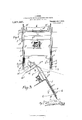
- Fig. 3 is a diagram in which is shown the path taken by the boat when there is a backward list of the vessel carrying the apparatus:-
- each boat is carried in a cradle which comprises a cranked beam at which passes under the keel of the boat Z) and is turned upwardly at each end (6
- the ends a of the beam a are each pivoted to one of the main supporting arms 0.
- the beam a isprovided with chocks or other means a fitted approximately to the shape of the under side of the boat 6 and adapted not only to support it but to enable it automatically to float freely upon reaching the water.
- the two supporting arms 0 each consists of a beam extending down the ships side and the upper end of which is bent backward at 0 allowing the boat I) to hang over the deck as shown in Fig. 2.
- Each arm 0 carries a bracket 0 some little distance from its upper end and the two brackets c are joined by the beam 0
- the rope or chain connected to the middle of the beam 0 and the said rope or chain extends over a winch d by which the apparatus is let down and drawn up.
- winch Any suitable form of winch may be employed but I prefer to use one of the kind having two drums onto one of which is wound the rope connected to the beam 0 the other drum being used to raise the boat from the Water by one of the alternative methods hereinafter described.
- the winch also comprises suitable braking means and also a locking clutch by which the winch can be locked in any desired position, the arrangement being such that when the apparatus has been raised the winch is locked by the clutch, and when it is desired to lower the apparatus the clutch is released and the brake is applied to the winch so that the apparatus descends at a speed controlled by the brake of the winch entirely by reason of its own weight.
- Each arm c is provided with a pin or roller 0" which is adapted to rest against an upright f carried by the ship. These pins bearing against the upright serve to steady the apparatus in its normal position and they also act as a fulcrum to the pull exerted from the winch. The pins 0 also serve as guides to the armsc for a short part of the descent.
- each arm a is pivoted to a link 6.
- the links 6 are pivoted at their other ends to brackets g fixed to the ships side.
- the links 6 are slightly bent at the points 0 and atthese points are pivoted
- the other end of each link it is connected to the arm 0 by a connecting link 3' pivoted to the arm 0 at 7'
- the link j is preferably forked for the greater part of its length and the link it preferably comprises two parallel members.
- a roller or pulley Projecting from the ships side near to the winch-is preferably placed a roller or pulley adapted to bear 013? the rope from the ships side when the arms are in their lower position.
- a protective plate 7c is provided.
- the plate acts as a guide and is provided with flanges 7: on each side with which the projecting ends of the pivot pin of the joint fastening the members It and j together contact.
- each flange 75 at the upper end is turned inward so as to make a three sided groove within which is guided the aforementioned pivot pin at the beginning of the downward movement, thus insuring that the said pivot pin will not move away from the ships side just at the moment of starting. This provision insures that at the start of the downward movement the links will commence to open out.
- a double cam Z consisting of a plate attached to the ships side the said cam being shaped to give the desired motion to the link It as it slides thereover.
- the locking clutch When the boat is ready to be launched the locking clutch is released from the winch and an operator manipulates the winch brake so as to check the downward movement of the boat if desired.
- the weight of the boat and the arms causes the arms to move downwardly as soon as the locking clutch has been released, the initial movement of the upper ends of the arms 0 being almost vertical as the pin or roller 0 slides down the upright If the pin or roller 0 were not provided the initial movement of the boat would be first in a downwardly inclined direction inboard and after a short distance has been traversed the boat would take the downwardly inclined direction. away from the side of the ship. This movement, however, is not desirable and the provision of the pin 0 and upright f renders the initial movement substantially vertical.
- the purpose of the cam Z is to keep the path of the boat straight and pass it smoothly into the circular part of its course. WVithout the cam Z the straight part of the course taken by the boat would not be tangential to the circular part and there would be a slight shock when the lower ends of the arms 0 touched the side of the ship. W hen the lower ends of the arms 0 come into contact with the side of the ship or with the buffers m which are preferably provided the motion which is governed by the link work is completed.
- the continued motion of the apparatus is a simple turning movement about the lower ends of the arms 0.
- Any extra boat which might be stored on the boat deck may be moved into such a po sition that it will be lifted by the cradle as it nears its highest position, and this second boat may, in turn, be launched in the same manner.
- One method of raising the boat from the water is to-provide a float attached to each arm 0 near the cradle pivots by a length of line.
- the arms 0 are sunk below the water and the boat is maneuvered between the floats which may then be lifted into the boat, one at the stem and one at the stern. to which the floats are attached are drawn in and kept taut while the arms 0 are gradually raised by the winch.
- the boat is thus kept directly over the cradle which as it rises will lift the boat and carry it up to its original position.
- an ordinary block tackle fastened to the extreme upper end of each arm 0 and the ropesfroin this tackle are passed pulleys it provided at the upper end of each arm a.
- These ropes are attached to a sin le rope which may be wound on the second.- barrel 0 the winch A line-is also attached to the beam of the cradle.
- the arms c are lowered and locked ina position some distance above the water and the cradle is pulled well to one side and fastened by the line provided.
- the block tackle is paid out until it can be accordingly attached in the ordinary way to the boat which is then drawn up by the tackle as far as possible until it is higher than the cradle.
- the cradle is then allowed to swing back into its vertical position and the boat is lowered into it.
- the power is then applied to the winch and the arms and the whole apparatus is drawn up.
- the apparatus forming the subject matter of this invention has many practice as by its use the boat 1s placed in the water well away from the ships side and during its entire course it is positively held and cannot be thrown against the side by the rolling of the ship. Moreover, there is no tackle of any kind to unhook. As soon as the boat is borne by the water it is automatically free of every attachment to the ship. Further, the boat does not need to be moved from its normal position and there are no preliminaries to be performed before the launch, beyond the removal of the boat cover. The locking clutch of the winch can be released by one man and the launch proceeds at once automatically, no power being required for launching either manually or mechanically.
- the apparatus is also suitable for launching large rafts. The most important advantage of the apparatus, however, is the fact that a safe launch can be effected with any degree of list on the launching side and with a considerable degree of list toward the opposite side.
- a boat-lowering apparatus comprising a cradle, a supporting arm for said cradle, a downwardly movable pivotal. bearing for said arm whereby the arm is adapted to gravitate under its load, and a guide and link members cooperating with said supporting arm forcing it outwardly and causing it to clear the hull as it gravitates.
- a boat-lowering apparatus comprising a cradle, a supporting arm for said cradle, a downwardly swinging pivoted lever, a pivotal bearing for the supporting arm mounted on said lever whereby the arm is adapted to gravitate under its load, and a guide and link members coiiperating with said supporting arm to force it outwardly during its descent.
- a boat-lowering apparatus comprising 1 cradle, a supporting arm for said cradle,
Landscapes
- Chemical & Material Sciences (AREA)
- Engineering & Computer Science (AREA)
- Combustion & Propulsion (AREA)
- Mechanical Engineering (AREA)
- Ocean & Marine Engineering (AREA)
- Ship Loading And Unloading (AREA)
Description
1. 310m. APPARATUS FOR RAISING AND LOWERING SHIPS BOATS;
APPLICATION FILED iUN'E 20. I916.
Patented July 2,1918.
J. STORIE.
APPARATUS FOR musmc AND LOWERING SHIPS BOATS.
APPLICATION FILED JUNE 20. 1916.
Patented ul 2, 1918.
2 suesrs-snm 2.
H.. Hn "MU 1m: NORRIS #5195 m. ruonumm" wnsrmvowm n. c,
JAMES stream, or nmnenzaerr, SCOTLAND.
APPARATUS FOR RAISING AND LOKVERIN SHIPS BOATS.
To all whom it may concern:
. Be it known that I, JAMES S'ronrn, a subject of theKing of the United Kingdom of Great Britain and Ireland, and resident of 2 Rossie Place, Edinburgh, Scotland, have invented certain new and useful Improvements Relating to Apparatus for Raising and Lowering Ships Boats, of which the following is a specification.
This invention relates to apparatus for raising and lowering ships boats and has for its object to provide an improved apparatus of simple construction which among other advantages will render it possible to launch boats from either side orboth sides of a ship which by accident or otherwise has been caused to have a serious list; to launch boats safely in rough weather, or while the l ship is rolling; and also while the ship is moving at a moderate speed.
My invention-relates to. that kind of apparatus which comprises a cradle or the like adapted to support a boat by pivotal or other supports at each end and arms adapted to support the said cradle, the said arms being substantially vertically disposed down the sides of the ship and pivotally mounted at their lower ends and means whereby the arms may be turned in a vertical plane about their lower ends. In arrangements of this class the arrangement is such that when it is required to launch a boat the arms are allowed to swing down, pivoting about their lower ends so that the cradle which is supported between the upper ends is swung wide of the side of the ship until the boat carried thereon reaches the water, when it automatically floats free of the cradle.
The use of vertically disposed arms pivoted at their lower ends and carrying boats at their upper ends for raising and lowering ships boats presents two difficulties, the first of which arises from the fact that the slightest backward list of the vessel will either put the arms out of action or necessitate the use of power in turning them downwardly so as to launch the boat.
This difiiculty has been overcome by the apparatus which I have invented, by the employment of an arrangement of links at the lower parts of the arms which allows the upper end of each arm to descend in a downwardly inclined line which is substan- Specification of Letters Patent. Patented July 2, 1918. Application filed June 20, 1916. Serial No. 104,741.
tially straight whereby every part of the course taken by the boat has a considerable downward inclination. It will be evident that when this condition obtains the weight of the boat and of the arms themselves will cause the boat to descend when the arms are unlocked even when there is a backward list of the vessel the apparatus. v
In the example of my'apparatus which is illustrated the design is such that the arms will descend as soon as they are unlocked while the vessel carrying the apparatus is in any position upv to a backward list of 35. By modifying the proportions of the link work effectiveness can be obtained for even a greater degree of inclination. If required the link work can be so designed that the descending path taken by the boat would be substantially vertical for some distance, say as far as the main deck, and subsequently dpiwnwardly inclined away from the ships s1 e.
The other obstacle in connection with the use of pivoted arms bf the kind mentioned for raising and lowering ships boats, is the difliculty of withdrawing the arms or supporting means from the boat instantly after the boat has reached the water. It is of extreme importance that this should be done as the proximity-of any rigid apparatus to a boat which is floating would behighly dangerous in rough weather.
This difficulty is overcomeby the use of the present apparatus in which after the boat has floated the arms and supporting means immediately and quickly sink Well which is fitted with I below the surface of the water until they again take up a position near the ships side. If necessary the arms or the supporting means may be specially weighted in order to insure that this action will take place.
The accompanying drawings illustrate by way of example one form of apparatus constructed in accordance wit-h the present invention.
Figure 1 is a view in side elevation. Fig. 2 is an end view showing the apparatus in three different positions.
Fig. 3 is a diagram in which is shown the path taken by the boat when there is a backward list of the vessel carrying the apparatus:-
additional links it.
In the construction illustrated each boat is carried in a cradle which comprises a cranked beam at which passes under the keel of the boat Z) and is turned upwardly at each end (6 The ends a of the beam a are each pivoted to one of the main supporting arms 0. The beam a isprovided with chocks or other means a fitted approximately to the shape of the under side of the boat 6 and adapted not only to support it but to enable it automatically to float freely upon reaching the water.
The two supporting arms 0 each consists of a beam extending down the ships side and the upper end of which is bent backward at 0 allowing the boat I) to hang over the deck as shown in Fig. 2. Each arm 0 carries a bracket 0 some little distance from its upper end and the two brackets c are joined by the beam 0 The rope or chain connected to the middle of the beam 0 and the said rope or chain extends over a winch d by which the apparatus is let down and drawn up.
Any suitable form of winch may be employed but I prefer to use one of the kind having two drums onto one of which is wound the rope connected to the beam 0 the other drum being used to raise the boat from the Water by one of the alternative methods hereinafter described. The winch also comprises suitable braking means and also a locking clutch by which the winch can be locked in any desired position, the arrangement being such that when the apparatus has been raised the winch is locked by the clutch, and when it is desired to lower the apparatus the clutch is released and the brake is applied to the winch so that the apparatus descends at a speed controlled by the brake of the winch entirely by reason of its own weight.
Each arm c is provided with a pin or roller 0" which is adapted to rest against an upright f carried by the ship. These pins bearing against the upright serve to steady the apparatus in its normal position and they also act as a fulcrum to the pull exerted from the winch. The pins 0 also serve as guides to the armsc for a short part of the descent.
The lower end 0 of each arm a is pivoted to a link 6. The links 6 are pivoted at their other ends to brackets g fixed to the ships side. The links 6 are slightly bent at the points 0 and atthese points are pivoted The other end of each link it is connected to the arm 0 by a connecting link 3' pivoted to the arm 0 at 7' The link j is preferably forked for the greater part of its length and the link it preferably comprises two parallel members.
Projecting from the ships side near to the winch-is preferably placed a roller or pulley adapted to bear 013? the rope from the ships side when the arms are in their lower position.
When the apparatus is lowered the point at which the link it is pivoted to the link slides down in contact with the ships side and in order that the side of the ship may not be damaged a protective plate 7c is provided. The plate it acts as a guide and is provided with flanges 7: on each side with which the projecting ends of the pivot pin of the joint fastening the members It and j together contact. As will be seen from Fig.
'1 the lower parts of the flanges 73 7& are
broadened out so as to facilitate the entry of the sliding part. A short part of each flange 75 at the upper end is turned inward so as to make a three sided groove within which is guided the aforementioned pivot pin at the beginning of the downward movement, thus insuring that the said pivot pin will not move away from the ships side just at the moment of starting. This provision insures that at the start of the downward movement the links will commence to open out.
Below the protective plate is provided a double cam Z consisting of a plate attached to the ships side the said cam being shaped to give the desired motion to the link It as it slides thereover.
It will be understood that the portion of the boat deck immediately under the boat is cut away so as to allow the boat to move freely into and out of the position shown at the top of Fig. 2.
When the boat is ready to be launched the locking clutch is released from the winch and an operator manipulates the winch brake so as to check the downward movement of the boat if desired. The weight of the boat and the arms causes the arms to move downwardly as soon as the locking clutch has been released, the initial movement of the upper ends of the arms 0 being almost vertical as the pin or roller 0 slides down the upright If the pin or roller 0 were not provided the initial movement of the boat would be first in a downwardly inclined direction inboard and after a short distance has been traversed the boat would take the downwardly inclined direction. away from the side of the ship. This movement, however, is not desirable and the provision of the pin 0 and upright f renders the initial movement substantially vertical. While the pin or roller 0 bears upon the upright f, the weight of the boat, with the pin or roller 0 as a fulcrum, tends to force the lower parts of the arms 0 outwardly thus opening out the links and at the same time the upper end of the link 72, comes slightly forward and descends for a short I The lines This outward driving force on the lower parts of thea'rmsc would be greater as the backward list of the vessel increased, (see Fig. 3), so that a ready start is insured even under the most disadvantageous conditions.
As the links begin to open out the upper end of the link it bears upon the plate and the link j forces the armsc forward and thepin or" relief 0 begins to leave the upright f. The arm 0 then continues its course down wardly supported by the links along with the winch rope, the upper end of the link it meanwhile sliding down the face of the plate 76 within the flanges Z0 en the point e turning about the point 9 has described about three quarters of its orbit of a semi-circle, the upper end of the link It comes into contact with the cam Z. The link it still partly slides but its motion over the cam Z. is mainly a rocking motion the upper end of the link moving away from the ships side and the lower end of the link moving down the cam Z.
The purpose of the cam Z is to keep the path of the boat straight and pass it smoothly into the circular part of its course. WVithout the cam Z the straight part of the course taken by the boat would not be tangential to the circular part and there would be a slight shock when the lower ends of the arms 0 touched the side of the ship. W hen the lower ends of the arms 0 come into contact with the side of the ship or with the buffers m which are preferably provided the motion which is governed by the link work is completed. The continued motion of the apparatus is a simple turning movement about the lower ends of the arms 0.
When the boat reaches the water it floats out of the cradle which continues to sink under the water until it reaches its lowest position. The arms are drawn up again when the boat has moved clear of the vicinity of the vessel.
Any extra boat which might be stored on the boat deck may be moved into such a po sition that it will be lifted by the cradle as it nears its highest position, and this second boat may, in turn, be launched in the same manner.
One method of raising the boat from the water is to-provide a float attached to each arm 0 near the cradle pivots by a length of line. The arms 0 are sunk below the water and the boat is maneuvered between the floats which may then be lifted into the boat, one at the stem and one at the stern. to which the floats are attached are drawn in and kept taut while the arms 0 are gradually raised by the winch. The boat is thus kept directly over the cradle which as it rises will lift the boat and carry it up to its original position. a
In an alternative method of raising the ofver boat an ordinary block tackle fastened to the extreme upper end of each arm 0 and the ropesfroin this tackle are passed pulleys it provided at the upper end of each arm a. These ropes are attached to a sin le rope which may be wound on the second.- barrel 0 the winch A line-is also attached to the beam of the cradle. The arms c are lowered and locked ina position some distance above the water and the cradle is pulled well to one side and fastened by the line provided. The block tackle is paid out until it can be accordingly attached in the ordinary way to the boat which is then drawn up by the tackle as far as possible until it is higher than the cradle. The cradle is then allowed to swing back into its vertical position and the boat is lowered into it. The power is then applied to the winch and the arms and the whole apparatus is drawn up. g
The apparatus forming the subject matter of this invention has many practice as by its use the boat 1s placed in the water well away from the ships side and during its entire course it is positively held and cannot be thrown against the side by the rolling of the ship. Moreover, there is no tackle of any kind to unhook. As soon as the boat is borne by the water it is automatically free of every attachment to the ship. Further, the boat does not need to be moved from its normal position and there are no preliminaries to be performed before the launch, beyond the removal of the boat cover. The locking clutch of the winch can be released by one man and the launch proceeds at once automatically, no power being required for launching either manually or mechanically. The apparatus is also suitable for launching large rafts. The most important advantage of the apparatus, however, is the fact that a safe launch can be effected with any degree of list on the launching side and with a considerable degree of list toward the opposite side.
Claims:
1. A boat-lowering apparatus comprising a cradle, a supporting arm for said cradle, a downwardly movable pivotal. bearing for said arm whereby the arm is adapted to gravitate under its load, and a guide and link members cooperating with said supporting arm forcing it outwardly and causing it to clear the hull as it gravitates.
2. A boat-lowering apparatus comprising a cradle, a supporting arm for said cradle, a downwardly swinging pivoted lever, a pivotal bearing for the supporting arm mounted on said lever whereby the arm is adapted to gravitate under its load, and a guide and link members coiiperating with said supporting arm to force it outwardly during its descent.
advantages in.
3. A boat-lowering apparatus comprising 1 cradle, a supporting arm for said cradle,
a downwardly and outwardly swinging pivoted lever, a pivotal bearing for the 5 supporting arm mounted on said lever where by the arm is adapted to gravitate under its load, and a guide and link members 00- Gopies of this patent may be obtai ned for five cents each, by addressing the Washington, I). 0.
operating with said supporting arm to force it outwardly during its descent.
JAMES STORIE.
\Vitnesses ALEXANDER STORIE,
MARY BELL.
Commissioner of Yatents,
Priority Applications (1)
| Application Number | Priority Date | Filing Date | Title |
|---|---|---|---|
| US10474116A US1271237A (en) | 1916-06-20 | 1916-06-20 | Apparatus for raising and lowering ships' boats. |
Applications Claiming Priority (1)
| Application Number | Priority Date | Filing Date | Title |
|---|---|---|---|
| US10474116A US1271237A (en) | 1916-06-20 | 1916-06-20 | Apparatus for raising and lowering ships' boats. |
Publications (1)
| Publication Number | Publication Date |
|---|---|
| US1271237A true US1271237A (en) | 1918-07-02 |
Family
ID=3338867
Family Applications (1)
| Application Number | Title | Priority Date | Filing Date |
|---|---|---|---|
| US10474116A Expired - Lifetime US1271237A (en) | 1916-06-20 | 1916-06-20 | Apparatus for raising and lowering ships' boats. |
Country Status (1)
| Country | Link |
|---|---|
| US (1) | US1271237A (en) |
Cited By (4)
| Publication number | Priority date | Publication date | Assignee | Title |
|---|---|---|---|---|
| US3593355A (en) * | 1969-05-01 | 1971-07-20 | Husbands Shipyards Ltd | Cradle device for a life raft or like dinghy |
| DE3314774A1 (en) * | 1983-04-23 | 1984-10-31 | Robert 2160 Stade Hatecke | Ship with lowerable boats, in particular lifeboats, and davit gear for a ship |
| DE3329159A1 (en) * | 1983-08-12 | 1985-02-21 | Robert 2160 Stade Hatecke | Ship with lowerable boats, in particular lifeboats |
| DE3348186C2 (en) * | 1983-08-12 | 1990-09-20 | Robert 2160 Stade De Hatecke |
-
1916
- 1916-06-20 US US10474116A patent/US1271237A/en not_active Expired - Lifetime
Cited By (4)
| Publication number | Priority date | Publication date | Assignee | Title |
|---|---|---|---|---|
| US3593355A (en) * | 1969-05-01 | 1971-07-20 | Husbands Shipyards Ltd | Cradle device for a life raft or like dinghy |
| DE3314774A1 (en) * | 1983-04-23 | 1984-10-31 | Robert 2160 Stade Hatecke | Ship with lowerable boats, in particular lifeboats, and davit gear for a ship |
| DE3329159A1 (en) * | 1983-08-12 | 1985-02-21 | Robert 2160 Stade Hatecke | Ship with lowerable boats, in particular lifeboats |
| DE3348186C2 (en) * | 1983-08-12 | 1990-09-20 | Robert 2160 Stade De Hatecke |
Similar Documents
| Publication | Publication Date | Title |
|---|---|---|
| US1164967A (en) | Aeroplane alighting and launching apparatus. | |
| EP2643204A2 (en) | Apparatus to launch and recover a boat | |
| US1271237A (en) | Apparatus for raising and lowering ships' boats. | |
| US2091327A (en) | Lifeboat launching apparatus | |
| US1116761A (en) | Apparatus for launching ships' boats. | |
| US3418671A (en) | Hoisting and launching apparatus for dinghy | |
| US1275399A (en) | Means for launching boats from ships. | |
| US2028513A (en) | Davit mechanism device for launching lifeboats | |
| US1913830A (en) | Device for handling boats and other loads | |
| US2319854A (en) | Gravity davit | |
| EP0489101B1 (en) | A system for launching a lifeboat | |
| US2949617A (en) | Ships' lifeboat davits | |
| US1191410A (en) | Means for launching a ship's boats. | |
| US2016838A (en) | Installation for handling a lifeboat | |
| US1344754A (en) | Boat supporting and launching apparatus for ships | |
| US1306645A (en) | torrie | |
| US1131411A (en) | Means for lowering boats at sea. | |
| US290342A (en) | mooney | |
| US1855013A (en) | Boat raising and lowering gear | |
| US1009753A (en) | Life-boat-handling apparatus. | |
| US2041817A (en) | Ship's davit | |
| US8894342B1 (en) | Automatically retractable boarding ramp assembly for a marine vessel | |
| US1116956A (en) | Automatic means for lowering life-boats. | |
| US1401919A (en) | Ship's davit | |
| US1130569A (en) | Life-boat-launching apparatus. |