US1237888A - Airship. - Google Patents
Airship. Download PDFInfo
- Publication number
- US1237888A US1237888A US12560116A US12560116A US1237888A US 1237888 A US1237888 A US 1237888A US 12560116 A US12560116 A US 12560116A US 12560116 A US12560116 A US 12560116A US 1237888 A US1237888 A US 1237888A
- Authority
- US
- United States
- Prior art keywords
- planes
- ship
- sections
- fin
- plane
- Prior art date
- Legal status (The legal status is an assumption and is not a legal conclusion. Google has not performed a legal analysis and makes no representation as to the accuracy of the status listed.)
- Expired - Lifetime
Links
- 230000003028 elevating effect Effects 0.000 description 9
- 238000010276 construction Methods 0.000 description 4
- 238000010586 diagram Methods 0.000 description 4
- ATJFFYVFTNAWJD-UHFFFAOYSA-N Tin Chemical compound [Sn] ATJFFYVFTNAWJD-UHFFFAOYSA-N 0.000 description 2
- 208000027418 Wounds and injury Diseases 0.000 description 2
- 230000006378 damage Effects 0.000 description 2
- 230000001771 impaired effect Effects 0.000 description 2
- 208000014674 injury Diseases 0.000 description 2
- 230000015572 biosynthetic process Effects 0.000 description 1
- 238000007664 blowing Methods 0.000 description 1
- 230000002349 favourable effect Effects 0.000 description 1
- 230000005484 gravity Effects 0.000 description 1
- 230000000630 rising effect Effects 0.000 description 1
- 230000000087 stabilizing effect Effects 0.000 description 1
- XLYOFNOQVPJJNP-UHFFFAOYSA-N water Substances O XLYOFNOQVPJJNP-UHFFFAOYSA-N 0.000 description 1
Images


Classifications
-
- B—PERFORMING OPERATIONS; TRANSPORTING
- B64—AIRCRAFT; AVIATION; COSMONAUTICS
- B64D—EQUIPMENT FOR FITTING IN OR TO AIRCRAFT; FLIGHT SUITS; PARACHUTES; ARRANGEMENT OR MOUNTING OF POWER PLANTS OR PROPULSION TRANSMISSIONS IN AIRCRAFT
- B64D27/00—Arrangement or mounting of power plants in aircraft; Aircraft characterised by the type or position of power plants
- B64D27/40—Arrangements for mounting power plants in aircraft
Definitions
- My invention relates more particularly to i aeroplanes and primarily to ships of this I the ship, and to provide means whereby one I 7 class constructed for war purposes.
- One object of the invention is to provide one or more auxiliary supporting planes for cooperation with the main supporting plane or planes incase of injury to the latter.
- Another object is to provide means Yet another object to locate the motors on opposite sides of the longitudinal axis of or more motors on either side of said axis may be dropped from the ship incase'the supporting efficiency of the plane or planes I chine with comparatively large balancing" and elevating planes for use at slow speed on either side of the craft be impaired.
- a still further object isto equip the maand with smaller planes for performing the same functions at high speed.
- Yet another object is to provide an improved type of collapsible fin to extend longitudinally of the ship to offer resistance in case the same should tend to turn sidewise in either direction due for instance to a strong wind blowing against the stabilizing or balancing planes when angled.
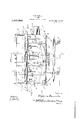
- Figure 1 is a side elevation of the improved air ship
- Fig. 5' is a diagram of thebalancing planes shown in 'Fig. 2;
- Fig. 6 is a similar view of' 'tl1e larger balancing planesdepicted in Fig. 4;
- Fig. 7 is another diagram of the balancing planes shown in Fig. 3.
- Fig. 8 is a diagram of, the course taken by Fig. 10 is an enlarged side elevation of the collapsible fin in operative position;
- FIG. 11 is a similar view with the fin collapsed
- Fig. 12 is a detail transverse section on the plane of the line 1212 of Fig. 11;
- Fig. 13 is ane'nlarged 'side elevation of one end'of thefin.
- Fig. 14 is a verticaltransverse section on the plane of the line 14-14 of Fig. 13 with the fin in operative position;
- Fig. 15 is a similar view on the line 15-15 of Fig. 13; i
- Fig. 16 is a duplicate of Fig. 15 with the exception that the fin is shown collapsed;
- Fig. 17 is a, detail horizontal section on. the planesindicated by the line 17.17 of The improvedship includes upper and lower main supporting planes S and S carried by a suitable framework which is preferably equipped with wheels W and pontoons P for landing on either land or water. I I I
- Hinged to the longitudinal" edges of the upper supporting plane S are two independently operable auxiliary supporting planes AS while similarly hinged to the front and rear ends of said plane 8 are speed checking planes SC.
- the planes AS may be provided with any suitable means for shifting them vertically, cables '1 being indicated in Fig. 9 for this purpose. It isessential, however, that the two-planes SC be moved 1n unison in opposite directions in order that they may be swung to the vertical positions indicated in dotted lines in Fig.
- cables 2 are preferably con- I nected therewith as depicted in Fig. l andso woundaround a roller or the like 3 as to move them in the required directions when said roller is turned by means of a hand I longitudinal axis is impaired by projectiles.
- the planes AS and SC may be extended as shown in the drawings but when the vessel is in range of anti-air craft guns of the enemy or is subject .to attack otherwise from above or below, the planes AS are swung vertically to the dotted line position depicted in Fig. 9 and thus will be much harder to strike than If new a portion of one of-the planes 6 or S to one side of the axis of the machine is injured, one of the auxiliary supporting planes AS will be immediately swung downward to the necessary extent to permit it to cooperate with the damaged plane in supporting the load.
- the motors M for the most part are disposed on opposite sides of'the longitudinal axis of the machine although some of said motors will preferably be located on said axis as will be clear from Figs. 3 and 4, and said motors will be releasably held in the mounts M preferably of the type depicted in my copcnding U. S. application, Serial Number 125.602.
- (lomparatively large balancing or equalizing planes B (Figs. 1, '-l and (ii are provided and may be used when the ship is traveling at a comparatively low lateof speed, while smaller balancing planes l3 (Figs. 3 and 7) and 15 (Figs. 2 and 5) are provided to be high rate of speed.
- the planes B are by prctercncc.located between thesupporting planes S and S and on opposite sides of the longitudinal axis of the ship, being turned on the other will be simultaneously tilted downwardly. any suitable operating means being here again employed.
- a rudder R for steering from side to sidc and a tin F extending longitudinally along the ccnterof the upper supporting planc S.
- the rudder R may be of any of the well known constructions but the fin F is of unique formation yet to be described.
- the improved ship is preferably equipped with a -turret 'l in which any number of rapidlirc guns or the like may be located, with a bomb dropping mechanism Bl) illustrated in detail in my copcnding U. S. ap-
- 'lhc lin F is. formed of a plurality of supcrimposcd lun'izontally extending flat'sections 10 disposed edge to edge and having their contacting edges beveled as shown at 11. the several sections being. adapted to be moved downwardly into side by side relation as shown clearly in Figs. 1, 9 aml 16;,-
- the ends of the sections 10 are mounted in laterally cxpansible guideways which are prefcrably formed as shown in' the drawings, consisting of rigid standards 12 at the opposite ends of the [in F, vertical bars 13 parallel with said standards, and spring devices 14 which normally move the bars 13 toward the standards, the ends of the sections being located between said bars and standards as shown most clearly in Fig. 17
- the fin F Under normal conditions the fin F is collapsedas indicated in. Fig, 1 but when run-' ning. toward a strong wind and tilting any dency .is for the entire s. ip, to turn sidewise.v When these conditions or similar ones are encountered, therefor,', the fin F is ims mediately thrown up to operative position and is allowed to remain in such position untilconditions are again favorable. This wise be used they willeooperate efi'ectively counteracts any-sidewise tendency as will be said planes SOservin mil clean. From the foregoing it is believed that-the general construction, uses and advantagesfof the ship will beobvious to those skilled in the'art, except that it may be'well to explain that i fthe planes A2 3 need not other-..
- the combination offone or more main supporting planes extending to opposite sides of the longitudinall ⁇ if the machine, propeller driving "motors on opposite sides of said longitudinal axis of the machine, means for releasing the'finotor 0r motors on, either side of saidfahis to p'er mit them to drop from the ship in injury'to thesupporting plane or planes at either side of said, 3X18, and normally fre tracted auxiliary supporting planes o i' op 'posite sldesof sa d axis f0r pro]ect1'on.;an,( l
- An aeroplane having front and rear speed checking planes hingedly mounted on transverse horizontal axes at the front and ed to be swung in opposite directions to vertical positions to retard the downward travel of the machine if falling endwise and to cause the same to alternately move for- ⁇ vardly and reanvardly on a zigzag course as it descends, said planes being independent of the elevating means of the ship.
- An air ship having one or more elevating planes for use at low speed,..one or more smaller elevating planes for use at high speed, one or more balancing planes to be used at low speed, and one or more smaller balancing planes for use at high speed.
- An air ship having propeller driving motors on opposite sides of its longitudinal axis ,and means for releasing the motor or motors .on either side of said axis to permit them to drop from the ship in case the weight carrying etliciency of the machine is reduced on either side of said axis.
- a vertical fin carried thereby and consistingof superimposed flat sections extending horizontally in edge to edge relation and adapted to lower into side to side relation, and one or more vertical guide members each having avertical slot to receive said fin, each slot having at its lower end an open throat to permit the several sections to leave and enter said slot when respectively lowered and raised, the adjacent edges of the several sections having contacting inclined faces to shift said sections laterally into the throat or throats when the upper section is shifted downwardly.
Landscapes
- Engineering & Computer Science (AREA)
- Aviation & Aerospace Engineering (AREA)
- Toys (AREA)
Description
A. FERNANDEZ.
AIRSHIP.
APPLICATION FILED OCT. 14. 19 1s.
1 ,2373888. Patented Aug. 21, 1917.
7SHEETS-SHEET I.
j amvehfoz WM mm I x I wyaonw gmaA/ade z 6] Home ma 0 A. FERNANDEZ.
AIRSHIP.
APPLICATION FILED OCT. 14, 1916.
Patented Aug. 21, 1917.
7 SHEETS-SHEET 2.
vwemtoi A. FERNANDEZ.
AIRSHIP.
APPLICATION FILED OCT. 14. 1916.
Patented Aug; 21, 1917.
1 SHEETSSHEE1 3.
ZES'KQSSQ a 3140014130; Wym gum/Dex A. FERNANDEZ.
AIRSHJP. APPLICATI-ONVFILED OCT. 14, 1916.
i 1,237,888. Patented Aug. 21, 1917.
ISHEETS-SHEET 4.
Qumran-tor A. FERNANDEZ.
AIRSHIP.
APPLICATION FILED OCT. 14, 1916.
Patented Aug. 21, 1917. v
ISHEETS-SHEET 5.
I 5114 w'ufoz MM/( 12% A. FERNANDEZ.
AIRSHIP.
APPLICATION FILED OCT. 14. I916.
Patented Aug. 21, 1917.
7SHEETS-SHEET 6- A. FERNANDEZ.
AIRSHIP.
APPLICATION FILED 00114. 1916.
Patented Aug. 21, 1917.
ISHEETS-SHEET 7.
wbentoz w H mi k E n,
Was/game gwwaM/ex {P1 TE sa e 1 ALPIioNsE rERN'AiwD z, or wAsH mGToN, DISTRICT or COLUMBIA. T
AIRSHIP.
Specification of Letters lfatent.
Patented A11 21', 1917.
Application filed'Oetober 14, 1916. Serial No. 125,601;
I To all whom z't mag concern I Be it known that I, ALPHONSE FERNANDEZ,
" a subject of the King of Spain, residing at Washington, in the District of Columbia,
have invented certain new and useful Imdescription of the invention, such as will I enable others skilled in the art to which it appertains to make and use the same.
My invention relates more particularly to i aeroplanes and primarily to ships of this I the ship, and to provide means whereby one I 7 class constructed for war purposes. I One object of the invention is to provide one or more auxiliary supporting planes for cooperation with the main supporting plane or planes incase of injury to the latter.
. Another object is to provide means Yet another object to locate the motors on opposite sides of the longitudinal axis of or more motors on either side of said axis may be dropped from the ship incase'the supporting efficiency of the plane or planes I chine with comparatively large balancing" and elevating planes for use at slow speed on either side of the craft be impaired.
A still further object isto equip the maand with smaller planes for performing the same functions at high speed. Yet another object is to provide an improved type of collapsible fin to extend longitudinally of the ship to offer resistance in case the same should tend to turn sidewise in either direction due for instance to a strong wind blowing against the stabilizing or balancing planes when angled.
lVith the foregoing general objects in view, the invention resides in certain novel features of construction and in unique combinatio11s of partsto be hereinafter fully described and claimed, the descriptive matter 1 being supplemented by the accompanying drawings which constitute a part of this application and in which: y
., Figure 1 is a side elevation of the improved air ship;
lines 3 3 and H of Fig. 1.
Fig. 13.
-wheel or the like 4.
Fig. 5'is a diagram of thebalancing planes shown in 'Fig. 2;
Fig. 6 is a similar view of' 'tl1e larger balancing planesdepicted in Fig. 4;
Fig. 7 is another diagram of the balancing planes shown in Fig. 3;
Fig. 8 is a diagram of, the course taken by Fig. 10 is an enlarged side elevation of the collapsible fin in operative position;
- Fig. 11 is a similar view with the fin collapsed;
Fig. 12 is a detail transverse section on the plane of the line 1212 of Fig. 11;
Fig. 13 is ane'nlarged 'side elevation of one end'of thefin.
Fig. 14: is a verticaltransverse section on the plane of the line 14-14 of Fig. 13 with the fin in operative position; Fig. 15 is a similar view on the line 15-15 of Fig. 13; i
Fig. 16 is a duplicate of Fig. 15 with the exception that the fin is shown collapsed;
Fig. 17 is a, detail horizontal section on. the planesindicated by the line 17.17 of The improvedship includes upper and lower main supporting planes S and S carried by a suitable framework which is preferably equipped with wheels W and pontoons P for landing on either land or water. I I
Hinged to the longitudinal" edges of the upper supporting plane S are two independently operable auxiliary supporting planes AS while similarly hinged to the front and rear ends of said plane 8 are speed checking planes SC. The planes AS may be provided with any suitable means for shifting them vertically, cables '1 being indicated in Fig. 9 for this purpose. It isessential, however, that the two-planes SC be moved 1n unison in opposite directions in order that they may be swung to the vertical positions indicated in dotted lines in Fig.
l for a purpose to be described.
For controlling the planes SC in the required mannera ny suitable mechanism may be provided but cables 2 are preferably con- I nected therewith as depicted in Fig. l andso woundaround a roller or the like 3 as to move them in the required directions when said roller is turned by means of a hand I longitudinal axis is impaired by projectiles.
.if they were extended.
When flying over friendly territory, the planes AS and SC may be extended as shown in the drawings but when the vessel is in range of anti-air craft guns of the enemy or is subject .to attack otherwise from above or below, the planes AS are swung vertically to the dotted line position depicted in Fig. 9 and thus will be much harder to strike than If new a portion of one of-the planes 6 or S to one side of the axis of the machine is injured, one of the auxiliary supporting planes AS will be immediately swung downward to the necessary extent to permit it to cooperate with the damaged plane in supporting the load. In this condition the chances are that the ship can at least proceed to friendly territory before landin If the pilot should be wounded or killed or should for other reasons lose control of the ship, the latter will descend slowly to the earth in a manner to be described provided the pilot has presence of mind to operate the hand wheel 4 to throw the speed checking planes SC to the positions shown in dotted lines in Fig. 1, it being also necessary that the motors be stopped. \V'ith the planes SC in the positions mentioned, they will form such resistance to the a' as to cause the ship to travel slowly on a zigzag course as indicated in diagram in Fi 8, moving alternately in forward and rearward directions.
The motors M for the most part are disposed on opposite sides of'the longitudinal axis of the machine although some of said motors will preferably be located on said axis as will be clear from Figs. 3 and 4, and said motors will be releasably held in the mounts M preferably of the type depicted in my copcnding U. S. application, Serial Number 125.602. By this arrangement of the motors if the weight carrying ctiicicncy of the machine to either side of its bombs or the like, not only can the plane AS on this side of the ship b'e swung to operative position, but one or more of the'motors can be rclcascd and dropped from the machine to rid the latter of as much weight may be necessary on the injured side, or any motor which may be damaged and therefore useless weight may also be dropped and will thus free the ship of an unnecessary load. H is to be lnulcrstood that when any motor M is rcleascd. thc ship must first be permitted to list sullicicntly to prevent said approaching a landing. comparatively large elevating planes [*1 will be employed, said planes being preferably located at or within the front end of the lower supporting plane employed when the craft is t'aveling at :1
S. \Vhen, however, the ship is traveling at a high rate of speed the use of the planes E even though tilted slightly would elevate or lower the ship too abruptly. I therefore provide smaller elevating planes E disposed at the front and rear of the ship and operated simultaneously in opposite directions by any well known or suitable mechanism. For illustrative purposes cables 5 are shown connected with the planes E,'said cables being operated in the required-manner by a hand wheel or the like (3.
(lomparatively large balancing or equalizing planes B (Figs. 1, '-l and (ii are provided and may be used when the ship is traveling at a comparatively low lateof speed, while smaller balancing planes l3 (Figs. 3 and 7) and 15 (Figs. 2 and 5) are provided to be high rate of speed. The planes B are by prctercncc.located between thesupporting planes S and S and on opposite sides of the longitudinal axis of the ship, being turned on the other will be simultaneously tilted downwardly. any suitable operating means being here again employed.
(omplcting the general structure of the ship is a rudder R for steering from side to sidc and a tin F extending longitudinally along the ccnterof the upper supporting planc S. The rudder R may be of any of the well known constructions but the fin F is of unique formation yet to be described.
The improved ship is preferably equipped with a -turret 'l in which any number of rapidlirc guns or the like may be located, with a bomb dropping mechanism Bl) illustrated in detail in my copcnding U. S. ap-
plication, Serial Number 125.603, and with a novel type of gasolcnc tank (l whose construction constitutes the subject matter of an application filcd by me and bearing Se-' rial Number P275604.
'lhc lin F is. formed of a plurality of supcrimposcd lun'izontally extending flat'sections 10 disposed edge to edge and having their contacting edges beveled as shown at 11. the several sections being. adapted to be moved downwardly into side by side relation as shown clearly in Figs. 1, 9 aml 16;,- The ends of the sections 10 are mounted in laterally cxpansible guideways which are prefcrably formed as shown in' the drawings, consisting of rigid standards 12 at the opposite ends of the [in F, vertical bars 13 parallel with said standards, and spring devices 14 which normally move the bars 13 toward the standards, the ends of the sections being located between said bars and standards as shown most clearly in Fig. 17
Slides 15-are carried by the standards 12 i and are shown in the present embodiment of the invention as equ pped with laterally extending pins 16 connected by chains or the like 17 withthe upper sections 10, theseveral movable sections being in turn provided V with any suitable pick up means such as 19 'are connected to the pins 16 and ass around drums 20 having a common sha t 21 the chains 18 of Fig. 13 for raising the other sections when the upper sectionisraised by 15 movement of the slide 15.
For shifting the slides 15 vertically, cables which may be operated in any preferred mannerfas by the chain 22 and crank 23 of Fig. 11. When'the shaft 21 is so turned as to pull slides 15 downwardly, the bev- 'eled edges-ofthe numerous sections 10 will' cause them'to 'as'sumethe position shown in "Fig. 16, the bars 13 having'yielded out- .wardly to permit this movement.
For-the purpose of'holdi'ngthe intermediate portions of the numerous sections 10 in' operative relation, vertical guide members 25 (Figs. 13, 15 @and 16). are provided, said members having vertical slots 26 to snugly receive s aid'sections, each slot, however, be-
guide the ing provided at its lower endifwith an open -,throat 27.;to permit the sections in question to'move laterally and assume the necessary relation when the fin lis collapsed; The throats 27 are so'shaped, however, asto-again v several 'sections'of the fin into the, slots 26, when the slides 15 are raised,-thechains 17 and 18 now coming intoplay to raise said sections, after which they will be w of the numerous balancin' planes, the ten rigidly held in operative f'relatio'n by the parts 12, 13, 14 and 25.
Under normal conditions the fin F is collapsedas indicated in. Fig, 1 but when run-' ning. toward a strong wind and tilting any dency .is for the entire s. ip, to turn sidewise.v When these conditions or similar ones are encountered, therefor,', the fin F is ims mediately thrown up to operative position and is allowed to remain in such position untilconditions are again favorable. This wise be used they willeooperate efi'ectively counteracts any-sidewise tendency as will be said planes SOservin mil clean. From the foregoing it is believed that-the general construction, uses and advantagesfof the ship will beobvious to those skilled in the'art, except that it may be'well to explain that i fthe planes A2 3 need not other-..
lanes SCin bringing the shi lie earth in the manner describe to prevent lateral e ship in its downwith the slowly to t p ng r ng 0 to opposite sidespf the longitudinal ax s of swung upwardly to vertical positions butbe-v or to a horizontal position to increase the all, it is tobe understood that the controls 5 forthe numerous planes and other mo'vin'g -parts will all be located Within easy'reach of thepilot and that the partsoperated from said controls will be highly sensitiveand thus quick inoperation. r Iclaimzl, Q
1. In an air ship, the combination of one or more mainwsupporting planes, elevating and balancingp'lanes, and one or-morefnormally retracted independentlyopei'ablaux Q5 iliary supporting planes for projectionand .cooperationiwiththe main supporting plane 1 or planes when the latter are injured,*tl ere by shifting; the center 0t gravity towardi'the uninjured parts and restoring equilibrium.
12. In an air ship, the combination offone or more main supporting planes extending to opposite sides of the longitudinall} (if the machine, propeller driving "motors on opposite sides of said longitudinal axis of the machine, means for releasing the'finotor 0r motors on, either side of saidfahis to p'er mit them to drop from the ship in injury'to thesupporting plane or planes at either side of said, 3X18, and normally fre tracted auxiliary supporting planes o i' op 'posite sldesof sa d axis f0r pro]ect1'on.;an,( l
when in ured.. I a v v 3. In an air ship, the: combination of a main supporting plane -or planesextending to opposite sides of the. longitudinalaxis of the machine, balancing and elevating: plane's, auxiliary independently projectable Y s'upporting planes hingedly connected to'tlie cooperation with the main supporting-planes lie ship and disposed onopposite sides-of said axis, said auxiliary planes-being normally swung'to vertical positions but being capa- I ble 0t swingingtoward or to a horizontal position to increase the supporting capacity of either side of the ship wheninju'red.
3 4 In-an air ship, the combination of a main supporting plane or planesinxtending them'a'chine, balancing and elevating planes, 12c auxiliary supporting planes hin ed to the slii'pan disposed on opposite si es of said axis, said auxiliary planes beingnormally ing capable, of swinging downward toward 1% supporting capacity of either-side Of the sh p when. injured, and front and rear speed,
checki g planes, hinged to the ship in. or
near tlie plane of the hinges of said aux- 1'30 rear edges of a supporting plane and adaptessary, and vertical guides in wh' iliary supporting planes, said speed checkzigzag course as it descends.
An aeroplane having front and rear speed checking planes hingedly mounted on transverse horizontal axes at the front and ed to be swung in opposite directions to vertical positions to retard the downward travel of the machine if falling endwise and to cause the same to alternately move for- \vardly and reanvardly on a zigzag course as it descends, said planes being independent of the elevating means of the ship.
6. An air ship having one or more elevating planes for use at low speed,..one or more smaller elevating planes for use at high speed, one or more balancing planes to be used at low speed, and one or more smaller balancing planes for use at high speed.
7, An air ship having propeller driving motors on opposite sides of its longitudinal axis ,and means for releasing the motor or motors .on either side of said axis to permit them to drop from the ship in case the weight carrying etliciency of the machine is reduced on either side of said axis.
8. The combination with an air ship, of a longitudinally disposed collapsible fin carriedthereby and consisting of a plurality of superimposed horizontally extending fiat sections disposed edge to edge, said sections being adapted to be lowered into sideby side relation when the use thereof is unnech the ends of said sections are slidably received.
H. The ('oi-nbination with an air ship, of frontand rear standards rising therefrom, a. tin consisting of a. plurality of superimposed horizontally extending flat sections disposed edge to edge and having their ends disposed ad acent said standards, slides mounted for vertical movement on said into side by side relation and said guideways expanding to permit this movement.
11. The combination with an air ship, of a vertical fin carried thereby and consisting of superimposed flat sections extending horizontally in edge to edge relation and adapted to lower into side to side relation, and one.or more vertical guide members each having a vertical slot to receive said fin, each slot having at its lower end an open throat to permit the several sections to leave and enter said slot when respectively lowered and raised.
12. The combination with an air ship, of
a vertical fin carried thereby and consistingof superimposed flat sections extending horizontally in edge to edge relation and adapted to lower into side to side relation, and one or more vertical guide members each having avertical slot to receive said fin, each slot having at its lower end an open throat to permit the several sections to leave and enter said slot when respectively lowered and raised, the adjacent edges of the several sections having contacting inclined faces to shift said sections laterally into the throat or throats when the upper section is shifted downwardly.
In testimony whereof I havehereunto set my hand in the presence of two subscribing ALPHONSE FERNANDEZ. Witnesses: t I V J. A. GRIESBAUER, T. A. Noornn witnesses.
Priority Applications (1)
| Application Number | Priority Date | Filing Date | Title |
|---|---|---|---|
| US12560116A US1237888A (en) | 1916-10-14 | 1916-10-14 | Airship. |
Applications Claiming Priority (1)
| Application Number | Priority Date | Filing Date | Title |
|---|---|---|---|
| US12560116A US1237888A (en) | 1916-10-14 | 1916-10-14 | Airship. |
Publications (1)
| Publication Number | Publication Date |
|---|---|
| US1237888A true US1237888A (en) | 1917-08-21 |
Family
ID=3305705
Family Applications (1)
| Application Number | Title | Priority Date | Filing Date |
|---|---|---|---|
| US12560116A Expired - Lifetime US1237888A (en) | 1916-10-14 | 1916-10-14 | Airship. |
Country Status (1)
| Country | Link |
|---|---|
| US (1) | US1237888A (en) |
-
1916
- 1916-10-14 US US12560116A patent/US1237888A/en not_active Expired - Lifetime
Similar Documents
| Publication | Publication Date | Title |
|---|---|---|
| US2673047A (en) | Foldable-winged craft | |
| US1237888A (en) | Airship. | |
| US1833033A (en) | Aeroship | |
| US1652554A (en) | Aircraft | |
| US1340053A (en) | Dirigible airship | |
| US1191501A (en) | Flying-machine. | |
| US1376675A (en) | Aircraft | |
| US1547912A (en) | Aircraft | |
| US1723479A (en) | Aeroplane | |
| US1603688A (en) | Airplane | |
| US889693A (en) | Air-ship. | |
| US981367A (en) | Air-craft. | |
| US1547434A (en) | Aircraft | |
| US1375297A (en) | Aeroplane | |
| US1645237A (en) | Airship | |
| US1990573A (en) | Transportation vehicle | |
| US1622676A (en) | Flying machine | |
| US1780410A (en) | Aeroplane | |
| US1318791A (en) | Aircraft. | |
| US1627191A (en) | Aeroplane-wing structure | |
| US1014031A (en) | Aerodrome. | |
| US1052204A (en) | Automatic balancing and horizontal sustaining aeroplane. | |
| US1127028A (en) | Flying-machine. | |
| US1302214A (en) | Aeroplane. | |
| US1264485A (en) | Wing for aeroplanes, flying, boats, &c. |